5
Deutsch
2 Sicherheitshinweise
Die Geräte (Kamera und Netzgerät) entsprechen
allen relevanten Richtlinien der EU und sind des-
halb mit gekennzeichnet.
WARNUNG Das Netzgerät wird mit lebens-
gefährlicher Netzspannung ver-
sorgt. Nehmen Sie daran keine
Eingriffe vor. Es besteht die Ge-
fahr eines elektrischen Schlages.
•
Schützen Sie die Kamera vor extremen Tem-
peraturen (zulässige Einsatztemperatur −40°C
bis +60°C).
•
Setzen Sie das Netzgerät nur im Innenbe-
reich ein und schützen Sie es vor Tropf- und
Spritzwasser und hoher Luftfeuchtigkeit. Der
zulässige Einsatztemperaturbereich beträgt
0– 40 °C.
•
Nehmen Sie die Geräte nicht in Betrieb und
ziehen Sie sofort den Netzstecker des Netz-
geräts aus der Steckdose:
1. wenn sichtbare Schäden an einem der Ge-
räte oder am Netzkabel vorhanden sind,
2.
wenn nach einem Sturz oder Ähnlichem der
Verdacht auf einen Defekt besteht,
3. wenn Funktionsstörungen auftreten.
Lassen Sie die Geräte in jedem Fall in einer
Fachwerkstatt reparieren.
•
Ziehen Sie den Netzstecker nie am Kabel aus
der Steckdose, fassen Sie immer am Stecker an.
•
Verwenden Sie zum Reinigen des Netzgeräts
nur ein trockenes, weiches Tuch, niemals Che-
mikalien oder Wasser. Die Kamera kann auch
mit einem feuchten Tuch und einem milden
Reinigungsmittel gesäubert werden.
•
Werden die Geräte zweckentfremdet, nicht
richtig angeschlossen, falsch bedient oder
nicht fachgerecht repariert, kann keine Haf-
tung für daraus resultierende Sach- oder Per-
sonenschäden und keine Garantie für die Ge-
räte übernommen werden. Ebenso kann keine
Haftung für durch Fehlbedienung oder durch
einen Defekt entstandene Datenverluste und
deren Folgeschäden übernommen werden.
Sollen die Geräte endgültig aus dem
Betrieb genommen werden, übergeben
Sie sie zur umweltgerechten Entsorgung
einem örtlichen Recyclingbetrieb.
3 Montage
1)
Um die optimale Montagestelle festzustel-
len, sollte ein Probebetrieb erfolgen. Dazu
die Kamera vorläufig in Betrieb nehmen
(☞folgende Kapitel). Lassen Sie zur Ver-
meidung von Kratzern während der Montage
die Schutzfolie auf der Kuppel (Handschuhe
liegen bei).
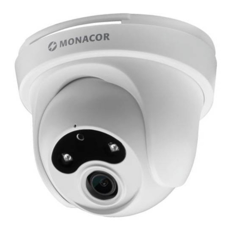
VORSICHT Bei Dunkelheit schalten sich die
IR-LEDs (2) ein. Blicken Sie beim Einrichten
der Kamera nicht aus der Nähe direkt in die
eingeschalteten IR-LEDs. Das Infrarotlicht
kann zu einer Reizung der Augen führen.
Die IR-Strahlung liegt allerdings weit un-
terhalb des Emissionsgrenzwertes und ist
risikofrei eingestuft nach EN62471.
2) Den Deckel (1) des Fachs auf der Rückseite
des Kameragehäuses nach Lösen der beiden
Schrauben öffnen und die Transportsiche-
rung (☞Pfeil in Abb. 3) der Kamera entfer-
nen. Den Deckel danach wieder verschließen.
Ebenso die Klebestreifen zum beweglichen
Teil der Kamera entfernen.
➂ Transportsicherung
3)
An der Montagestelle vier Löcher für die
Befestigung der Montageplatte (6) der
Wandhalterung und ggf. ein Loch für das
Anschlusskabel bohren (das Kabel kann alter-
nativ durch eine der Durchbruchstellen seit-
lich oder unterhalb des Sockels herausgeführt
werden). Eine Bohrschablone liegt bei. Bei
Bedarf die beiliegenden Dübel verwenden.
4)
Das Kabel der Kamera durch das Rohr der
Wandhalterung führen und die Halterung mit
den drei Inbusschrauben (4) auf der Oberseite
der Kamera befestigen. Mit der Schraube (5)
die Kamera gegen Verdrehen sichern.
5)
Die Wandhalterung mit den vier langen
Kreuzschlitzschrauben an der Montagestelle
befestigen.
