manuals.online logo
Brands
  1. Home
  2. •
  3. Brands
  4. •
  5. Monacor
  6. •
  7. Security Camera
  8. •
  9. Monacor TVCCD-24M User manual

Monacor TVCCD-24M User manual

®
CCTV-S/W-Kameramodul
1 Einsatzmöglichkeiten
Das Schwarzweißkameramodul TVCCD-24M eignet
sich für den Einsatz in Video-Überwachungs- und
Alarmanlagen. Dank der äußerst geringenAbmessun-
gen lässt es sich optimal als Türspion oder versteckte
Überwachungskamera verwenden.
Das Modul ist mit einem Fixfokus-Objektiv ausge-
stattet und verfügt über eine automatische Verstär-
kungsregelung (AGC), einen automatischen elektroni-
schen Verschluss und eine Gegenlichtkompensation.
2 Hinweise für den sicheren Gebrauch
●Das Kameramodul ist nach der EMV-Richtlinie
89/336/EWG (EMV = Elektromagnetische Verträg-
lichkeit) aufgebaut. Damit es auch im Betrieb diese
Richtlinie erfüllt, muss es in ein abgeschirmtes Ge-
häuse eingesetzt und der Videoausgang muss über
eine abgeschirmte Leitung angeschlossen werden.
Wird die EMV-Richtlinie nicht eingehalten, erlischt
die Konformitätserklärung.
●Schützen Sie das Modul vor Feuchtigkeit und Hitze
(zulässiger Einsatztemperaturbereich 0 –40°C).
●Schützen Sie die Linsen des Objektivs unbedingt
vor Staub und sonstiger Verschmutzung. Berühren
Sie sie auf gar keinen Fall mit den Fingern.
●Wird das Modul zweckentfremdet, falsch ange-
schlossen oder nicht fachgerecht repariert, kann für
eventuelle Schäden keine Haftung übernommen
werden.
●Soll das Modul endgültig aus dem Betrieb genom-
men werden, übergeben Sie es zur umweltgerech-
ten Entsorgung einem örtlichen Recyclingbetrieb.
3 Anschluss des Kameramoduls
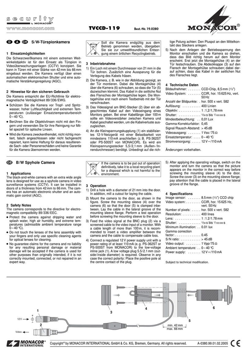
Das Modul wird über die 4-polige Buchse angeschlos-
sen (siehe Abb.):
Pin 1 = +12V (roter Anschlussdraht)
Pins 2 und 4 = Masse (schwarzer Anschlussdraht)
Pin 3: =Videoausgang(blauerAnschlussdraht)
3.1 Stromversorgung
Ein elektronisch stabilisiertes 12-V-Netzgerät (z.B.
PS-12CCD oder PS-128A von MONACOR) mit dem
roten Anschlussdraht (+12V) und dem schwarzen
Anschlussdraht (Masse) verbinden. Dabei auf die rich-
tige Polung achten. Die Stromaufnahme beträgt ca.
40mA.
3.2 Videoausgang
An den blauen Anschlussdraht (Video) die Kabel-
seele, an den schwarzen Anschlussdraht (Masse) die
Abschirmung eines 75-Ω-Koaxialkabels anschließen
und das Kabel mit dem Videoeingang eines Monitors
verbinden.
4 Inbetriebnahme
Nach dem Videoanschluss und demAnlegen der 12-V-
Versorgungsspannung ist das Modul betriebsbereit.
Die Schutzkappe über dem Objektiv abnehmen und
das Modul genau auf den Überwachungsbereich aus-
richten.
Wird das zu überwachende Objekt nicht scharf ab-
gebildet, das Auflagemaß korrigieren: Das Objektiv
vorsichtig so weit herein- bzw. herausdrehen, bis das
Bild scharf ist.
5 Technische Daten
Bildabtaster: . . . . . . . . . 6,3-mm-CMOS-Chip (1/4")
Synchronisation: . . . . . . hor. 15625Hz, vert. 50Hz
(CCIR)
Anzahl der Bildpunkte: . hor. 384 x vert. 287
Auflösung: . . . . . . . . . . . 240 Linien
Objektiv: . . . . . . . . . . . . 1:2,0/2,5mm
Mindestbeleuchtung: . . . 0,5Lux
Signal/Rauschabstand: > 45dB
Autom. elektronischer
Verschluss: . . . . . . . . . . 1/50 –1/148000 s
Videoausgang: . . . . . . . 1Vss, 75Ω
Einsatztemperatur: . . . . 0–40°C
Stromversorgung: . . . . . 12V , 40mA
Abmessungen, Gewicht: 24 x 24 x 27mm, 12g
Laut Angaben des Herstellers. Änderungen vorbehalten.
CCTV B/W Camera Module
1 Applications
The black/white camera module TVCCD-24M is suit-
able for the use in video monitoring systems and alarm
systems. Due to its small dimensions it can be used in
an optimum way as a door spy or concealed monitor-
ing camera.
The module has a fixfocus lens and is equipped
with an automatic gain control (AGC), an automatic
electronic shutter, and a backlight compensation.
2 Safety Notes
●The camera module corresponds to the EMC di-
rective 89/336/EEC (EMC = electromagnetic com-
patibility). To conform to this directive also in oper-
ation, the module must be placed into a shielded
housing and the video output must be connected via
a shielded cable. If the EMC directive is not com-
plied with, the declaration of conformity expires.
●Protect the module against humidity and heat (ad-
missible ambient temperature range 0–40°C).
●The lenses of the lens assembly must be protected
against dust and other impurities and must not be
touched with fingers in any case.
●If the module is used for other purposes than orig-
inally intended, if it is connected in the wrong way or
not repaired by authorized, skilled personnel, no lia-
bility can be taken over for possible damage.
●If the module is to be put out of operation definitively,
take it to a local recycling plant for a disposal which
is not harmful to the environment.
3 Connection of the Camera Module
The module is connected via the 4-pole jack (see
figure):
pin 1 = +12V (red wire)
pins 2 and 4 = ground (black wire)
pin 3: = video output (blue wire)
3.1 Power supply
Connect an electronically regulated 12V power supply
(e.g. PS-12CCD or PS-128A by MONACOR) with the
red wire (+12V) and the black wire (ground). Observe
the correct polarity. The power consumption is approx.
40mA.
3.2 Video output
Connect the cable core of a 75Ωcoaxial cable to the
blue wire (video) and the screen of the cable to the
black wire (ground). Connect the cable with the video
input of a monitor.
4 Setting into Operation
After carrying out the video connection and applying
the 12V supply voltage the camera module is ready
for operation. Remove the protection cap of the lens
and adjust the module exactly to the monitoring area.
If the object to be monitored is not clearly repro-
duced, correct the mechanical focus setting: carefully
turn the lens clockwise or counterclockwise until the
picture is clear.
5 Specification
Image sensor: . . . . . . . . 6.3mm CMOS chip (1/4")
Synchronization: . . . . . . hor. 15625Hz, vert. 50Hz
(CCIR)
Number of pixels: . . . . . hor. 384 x vert. 287
Resolution: . . . . . . . . . . 240 TV lines
Lens: . . . . . . . . . . . . . . . 1:2.0/2.5mm
Minimum illumination: . . 0.5lux
S/N ratio: . . . . . . . . . . . > 45dB
Automatic electronic
shutter: . . . . . . . . . . . . . 1/50 –1/148 000 s
Video output: . . . . . . . . . 1Vpp, 75Ω
Ambient temperature: . . 0–40°C
Power supply: . . . . . . . . 12V , 40mA
Dimensions: . . . . . . . . . 24 x 24 x 27mm
Weight: . . . . . . . . . . . . . 12g
According to the manufacturer.
Subject to technical changes.
1 2
3 4
12
V
Video
TVCCD-24M Best.-Nr. 19.5790
Copyright©by MONACOR®INTERNATIONAL GmbH & Co. KG, Bremen, Germany. All rights reserved. 05.02.02
®
D A CH
GB
Copyright©by MONACOR®INTERNATIONAL GmbH & Co. KG, Bremen, Germany. All rights reserved. 05.02.02
®
®
Module caméra CCTV n/b
1 Possibilités d'utilisation
Le module caméra noir et blanc TVCCD-24M est con-
çu pour une utilisation dans des centrales de surveil-
lance vidéo et d'alarme. Ses petites dimensions per-
mettent de l’utiliser comme espion de porte ou comme
caméra de surveillance cachée.
Le module caméra dispose d’un objectif à focale
fixe et est doté d’un réglage automatique d’amplifica-
tion (AGC), d’une obturation électronique automatique
et d’une compensation du contre-jour.
2 Conseils importants d’utilisation
●Le module répond à la norme européenne 89/336/
CEE portant sur la compatibilité électromagnétique.
Afin que le module y corresponde lorsqu’il est en
fonction, il doit être placé dans un boîtier blindé et la
sortie vidéo doit être reliée par un câble blindé. Si
les modalités de cette norme ne sont pas respec-
tées, la déclaration de conformité devient caduque.
●Protégez le module de l'humidité et de la chaleur
(température ambiante admissible 0–40°C).
●Protégez les lentilles de l’objectif de la poussière et
de toute autre salissure; en aucun cas, ne les tou-
chez jamais avec les doigts.
●Nous déclinons toute responsabilité en cas de dom-
mage si le module est utilisé dans un but autre que
celui pour lequel il a été conçu, s'il n'est pas correc-
tement branché ou n’est pas réparée par un techni-
cien habilité.
●Lorsque le module de caméra est définitivement
retiré du service, vous devez le déposer dans une
usine de recyclage adaptée pour contribuer à son
élimination non polluante.
3 Branchements
Le module caméra est branché par la prise 4 pôles
(voir schéma):
pin 1 = +12V (câble rouge)
pins 2 et 4 = masse (câble noir)
pin 3: = sortie vidéo (câble bleu)
3.1 Alimentation
Reliez une alimentation stabilisée 12V (p.ex. PS-
12CCD ou PS-128A de MONACOR) au câble rouge
(+12V) et au câble noir (masse). Veillez à respecter la
polarité. La consommation est de 40mA environ.
3.2 Sortie vidéo
Reliez l'âme d’un câble coaxial 75Ωau câble bleu
(vidéo) et le blindage du câble coaxial au câble noir
(masse). Reliez le cable coaxial à l’entrée vidéo d’un
moniteur.
4 Utilisation
Une fois le branchement vidéo effectué et le module
sous tension, il est prêt à fonctionner. Retirez le cou-
Modulo per videocamere CCTV b/n
1 Possibilità d'impiego
Il modulo per videocamere b/n TVCCD-24M è pre-
visto per l’impiego in impianti d’allarme e di sorveglian-
za video, e grazie alle ridotte dimensioni può essere
usato comodamente in porte come spie oppure come
videocamera di sorveglianza nascosta.
Il modulo è equipaggiato con un obiettivo a fuoco
fisso e dispone di una regolazione automatica del gua-
dagno (AGC), di un otturatore elettronico automatico
e di una compensazione della controluce.
2 Avvisi importanti
●Il modulo è costruito secondo la direttiva EMC (com-
patibilità elettromagnetica) 89/336/CEE. Per corri-
spondere a questa direttiva anche durante il fun-
zionamente, il modulo deve essere montato in un
contenitore schermato e l’uscita video dev'essere
collegata tramite un conduttore schermato. Se non
vene rispettata la direttiva EMC, la dichiarazione di
conformità perde ogni valore.
●Proteggere il modulo dall'umidità e dal calore (tem-
peratura d'impiego ammessa 0–40°C).
●Proteggere le lenti dell'obiettivo dalla polvere e dallo
sporco in genere. Non toccarle con le dita.
●Nel caso di uso improprio, di collegamenti sbagliati
o di riparazione non a regola d’arte non si assume
nessuna responsabilità per eventuali danni.
●Se si desidera eliminare il modulo definitivamente,
consegnarlo per lo smaltimento ad un’istituzione lo-
cale per il riciclaggio.
3 Collegamento del modulo
Il modulo viene collegato mediante la presa a 4 poli
(vedi figura):
pin 1 = +12V (conduttore rosso)
pins 2 e 4 = massa (conduttore nero)
pin 3: = uscita video (conduttore blu)
3.1 Alimentazione
Collegare il conduttore rosso (+12V) e il conduttore
nero (massa) con un alimentatore di rete 12V stabiliz-
zato elettronicamente (p.es. PS-12CCD oppure PS-
128A della MONACOR). Fare attenzione a non inver-
tire la polarità. L’assorbimento è di 40mA circa.
3.2 Uscita video
Collegare il conduttore blu (video) con l’anima e il con-
duttore nero (massa) con la schermatura di un cavo
coassiale 75Ωe collegare quest’ultimo con l’ingresso
video di un monitor.
4 Messa in funzione
Dopo il collegamento video ed elettrico 12V, il modulo
è pronto. Staccare il cappuccio di protezione dell’obiet-
tivo e orientare il modulo presisamente sulla zona da
sorvegliare.
Se l’oggetto da sorvegliare non è a fuoco, occorre cor-
reggere la posizione dell’obiettivo. Per fare ciò girare
l’obiettivo delicatamente in senso orario o in senso
antiorario finché l’immagine è a fuoco.
5 Dati tecnici
Sensore ottico: . . . . . . . chip CMOS 6,3mm (1/4")
Sincronizzazione: . . . . . orizz. 15625Hz, vert. 50Hz
(CCIR)
Numero pixel: . . . . . . . . orizz. 384 x vert. 287
Risoluzione: . . . . . . . . . 240 righe TV
Obiettivo: . . . . . . . . . . . . 1:2,0/2,5mm
Illuminazione minima: . . 0,5Lux
Rapporto S/R: . . . . . . . . > 45dB
Otturatore elettronico
automatico: . . . . . . . . . . 1/50 –1/148 000 s
Uscita video: . . . . . . . . . 1Vpp, 75Ω
Temperatura d’impiego: 0–40°C
Alimentazione: . . . . . . . 12V , 40mA
Dimensioni: . . . . . . . . . . 24 x 24 x 27mm
Peso: . . . . . . . . . . . . . . . 12 g
Dati forniti dal costruttore.
Con riserva di modifiche tecniche.
TVCCD-24M Best.-Nr. 19.5790
F B CH
I
vercle de protection de l’objectif et orientez le module
précisément vers la zone de surveillance.
Si l’image de l’objet à surveiller n’est pas nette,
vous devez effectuer des réglages sur l’objectif: tour-
nez l’objectif avec précaution dans le sens des aiguil-
les d’une montre ou dans le sens inverse jusqu’à ce
que l’image soit nette.
5 Caractéristiques techniques
Système: . . . . . . . . . . . . 6,3mm (1/4") puce CMOS
Synchronisation: . . . . . . hor. 15625Hz, vert. 50Hz
(CCIR)
Nombre de points: . . . . . hor. 384 x vert. 287
Resolution: . . . . . . . . . . 240 lignes
Objectif: . . . . . . . . . . . . . 1:2,0/2,5mm
Luminosité minimale: . . 0,5lux
Rapport signal/bruit: . . . > 45dB
Obturation électronique
automatique: . . . . . . . . . 1/50 –1/148 000 s
Sortie vidéo: . . . . . . . . . 1Vcc, 75Ω
Température ambiante: . 0–40°C
Alimentation: . . . . . . . . . 12V , 40mA
Dimensions: . . . . . . . . . 24 x 24 x 27mm
Poids: . . . . . . . . . . . . . . 12g
D’après les données du constructeur.
Tout droit de modification réservé.
1 2
3 4
12
V
Video

This manual suits for next models

1

Other Monacor Security Camera manuals

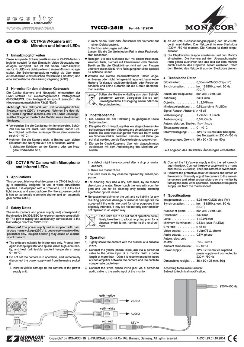
Monacor INC-150WIFI User manual

Monacor

Monacor INC-150WIFI User manual

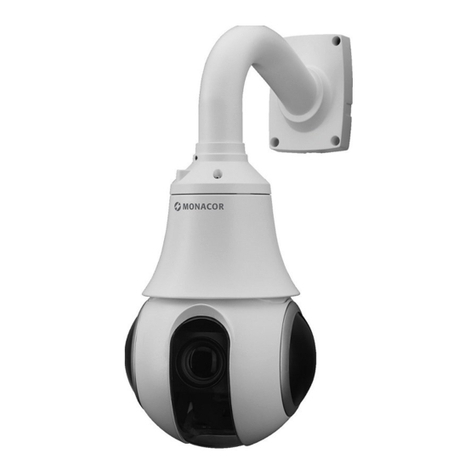
Monacor HDCAM-650 User manual

Monacor

Monacor HDCAM-650 User manual

Monacor TVCCD-150SET User manual

Monacor

Monacor TVCCD-150SET User manual

Monacor TVCCD-147COL User manual

Monacor

Monacor TVCCD-147COL User manual

Monacor TVCCD-187HCOL User manual

Monacor

Monacor TVCCD-187HCOL User manual

Monacor TVCCD-370COL User manual

Monacor

Monacor TVCCD-370COL User manual

Monacor TVCCD-147COL User manual

Monacor

Monacor TVCCD-147COL User manual

Monacor TVCCD-140IR User manual

Monacor

Monacor TVCCD-140IR User manual

Monacor TVCCD-123COL User manual

Monacor

Monacor TVCCD-123COL User manual

Monacor TVCCD-157SET User manual

Monacor

Monacor TVCCD-157SET User manual

Monacor TVCCD-180 User manual

Monacor

Monacor TVCCD-180 User manual

Monacor TVCCD-280 User manual

Monacor

Monacor TVCCD-280 User manual

Monacor security TVCCD-250SET User manual

Monacor

Monacor security TVCCD-250SET User manual

Monacor TVCCD-182HCOL User manual

Monacor

Monacor TVCCD-182HCOL User manual

Monacor TVCAM-150BV User manual

Monacor

Monacor TVCAM-150BV User manual

Monacor TVCCD-30 User manual

Monacor

Monacor TVCCD-30 User manual

Monacor security DVT-410SET User manual

Monacor

Monacor security DVT-410SET User manual

Monacor ELAX-2812DPTZ User manual

Monacor

Monacor ELAX-2812DPTZ User manual

Monacor VIEWEX-370 User manual

Monacor

Monacor VIEWEX-370 User manual

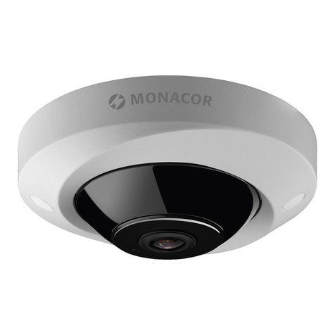
Monacor AHCAM-310DF User manual

Monacor

Monacor AHCAM-310DF User manual

Monacor TVCCD-350 User manual

Monacor

Monacor TVCCD-350 User manual

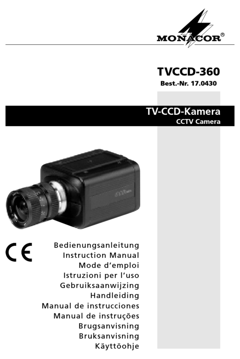
Monacor TVCCD-360 User manual

Monacor

Monacor TVCCD-360 User manual

Monacor TVCCD-350COL User manual

Monacor

Monacor TVCCD-350COL User manual

Monacor ELIP-2036BF User manual

Monacor

Monacor ELIP-2036BF User manual

Popular Security Camera manuals by other brands

EverFocus EZ350 User's manual and operation instructions

EverFocus

EverFocus EZ350 User's manual and operation instructions

VADDIO IntelliSHOT 999-21100-000 Complete manual

VADDIO

VADDIO IntelliSHOT 999-21100-000 Complete manual

GeoVision GV-IPCam Series Hardware manual

GeoVision

GeoVision GV-IPCam Series Hardware manual

Novus NVIP-2V-4202 quick start guide

Novus

Novus NVIP-2V-4202 quick start guide

ALIBI ALI-NP3016RH Quick installation guide

ALIBI

ALIBI ALI-NP3016RH Quick installation guide

Panasonic BB-HCM371A - Outdoor Wireless Network Camera operating instructions

Panasonic

Panasonic BB-HCM371A - Outdoor Wireless Network Camera operating instructions

advidia M-44-V-T-V2 quick guide

advidia

advidia M-44-V-T-V2 quick guide

Sony SuperExwave SSC-E473 operating instructions

Sony

Sony SuperExwave SSC-E473 operating instructions

TRASSIR TR-D1120WD user manual

TRASSIR

TRASSIR TR-D1120WD user manual

Speco O5T2 user manual

Speco

Speco O5T2 user manual

Sanyo VCB-3442P instruction manual

Sanyo

Sanyo VCB-3442P instruction manual

Matchmaster 50MM-WN8CH2TB4B quick guide

Matchmaster

Matchmaster 50MM-WN8CH2TB4B quick guide

Uniq UC-800CL user manual

Uniq

Uniq UC-800CL user manual

Dahua HD Fisheye quick start guide

Dahua

Dahua HD Fisheye quick start guide

Photon Focus MV1-D1024E user manual

Photon Focus

Photon Focus MV1-D1024E user manual

Axis AXIS 232D+ datasheet

Axis

Axis AXIS 232D+ datasheet

wavestore Vision WV-8S-180-AI installation guide

wavestore

wavestore Vision WV-8S-180-AI installation guide

RIVATECH RC3512HD-6311IR Quick installation guide

RIVATECH

RIVATECH RC3512HD-6311IR Quick installation guide

manuals.online logo
manuals.online logoBrands
  • About & Mission
  • Contact us
  • Privacy Policy
  • Terms and Conditions

Copyright 2025 Manuals.Online. All Rights Reserved.