Mopec HB Series User manual

Product User Manual HB series 1
Refrence Manual
HB SERIES DISSECTION TABLES WITH HINGED COVERS
JUL 2022
Version 1

Product User Manual HB series 2
DISCLAIMER
Copyright © 2022 by MOPEC
All rights reserved. No part of this publication may be reproduced, distributed, or transmitted in any form or by any
means, including photocopying, recording, or other electronic or mechanical methods, without the prior written
permission of the publisher. For permission requests, write to the publisher, addressed “Attention: Permissions
Coordinator,” at the address below.
Mopec
800 Tech Row, Madison Heights, MI 48071
Phone: 1-800-362-8491 email: [email protected]
Owner’s Record
Model No.: __________________________________
Serial No.: __________________________________
Voltage: __________________________________
Dealers Name: __________________________________
Dealers Address: _________________________________
Date of Purchase: ________________________________
Document Revisions
Date
Version Number
Document Changes
07-27-2022
1.0
Initial Release

Product User Manual HB series 3

Product User Manual HB series 4
Table of Contents
1!PREFACE ........................................................................................................................................... 6!
1.1!....!Description of the Equipment .......................................................................................................... 6!
1.2!....!Notations Used in This Manual ........................................................................................................ 6!
1.3!....!Models covered in this Manual ........................................................................................................ 6!
1.4!....!Explanation of Safety Warnings ...................................................................................................... 7!
1.5!....!Obtaining Instructions ..................................................................................................................... 7!
1.5.1!Internet ........................................................................................................................................................ 7!
1.5.2!Ordering Documentation ............................................................................................................................. 7!
1.5.3!Documentation Feedback ............................................................................................................................ 7!
2!Description of the product .............................................................................................................. 8!
2.1!....!Purpose of the Product .................................................................................................................... 8!
2.2!....!Technical Data ................................................................................................................................. 8!
2.3!....!Product Compliance ......................................................................................................................... 8!
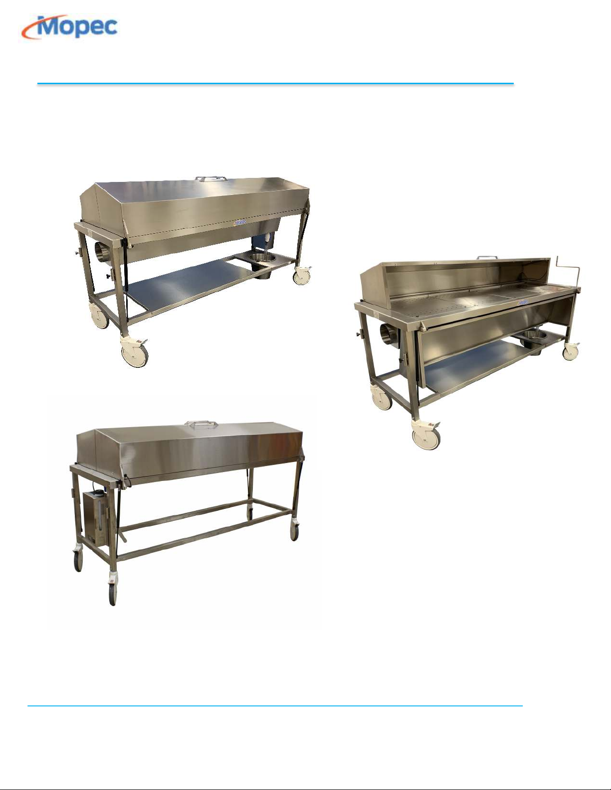
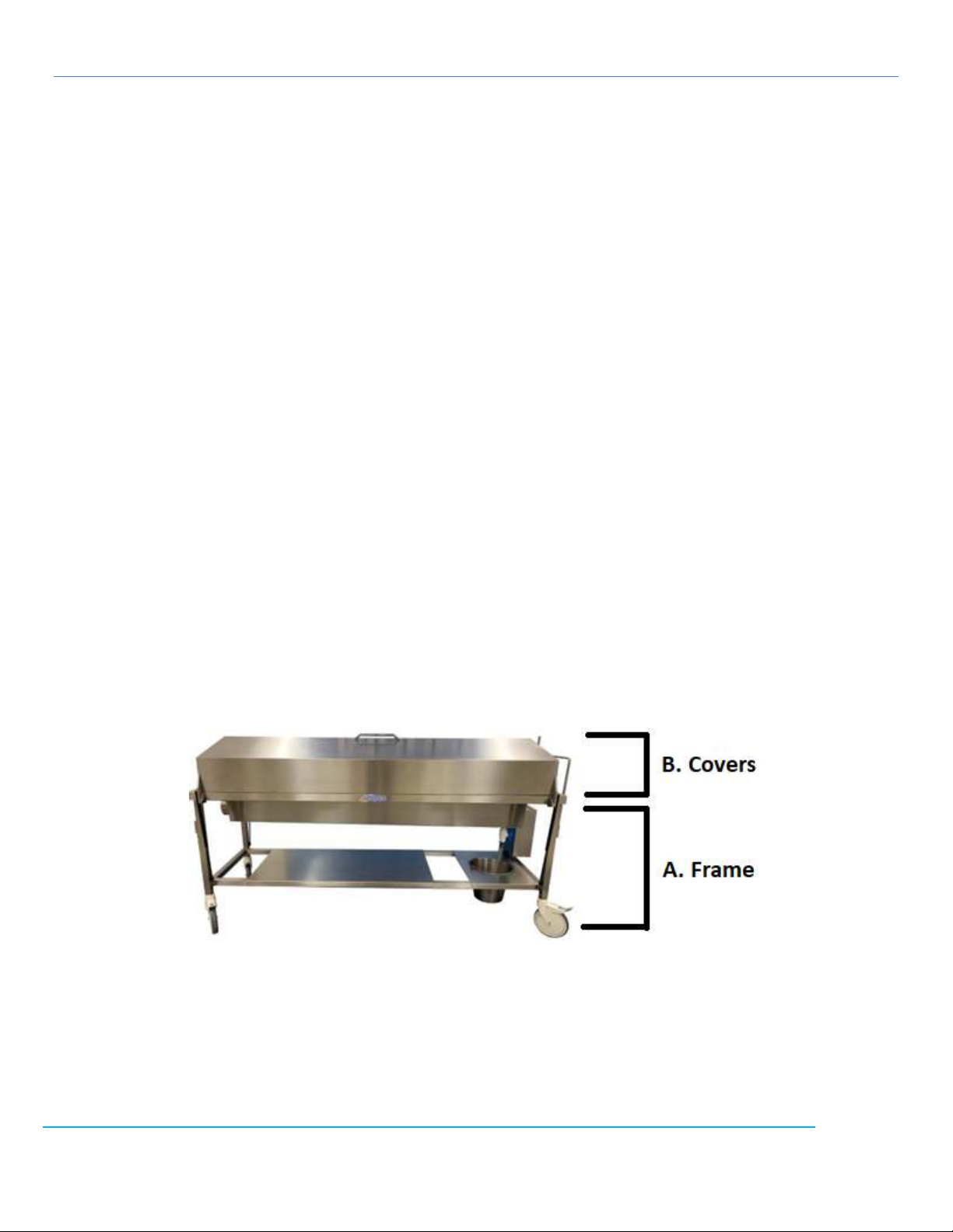
2.4!....!Product elements ............................................................................................................................. 8!
2.5!....!Warranty Statement ........................................................................................................................ 9!
3!Installation ..................................................................................................................................... 10!
3.1!....!How to unpackage your workstation ............................................................................................. 10!
3.1.1!Check for freight damage .......................................................................................................................... 10!
3.1.2!Uncrating Contents .................................................................................................................................... 10!
3.1.3!Transporting Unit to final location ............................................................................................................ 10!
3.1.4!Ventilation connection (in-house ventilation) ........................................................................................... 10!
3.2!....!Decommissioning the Unit ............................................................................................................. 10!
3.2.1!Decontaminate the unit. ........................................................................................................................... 10!
3.3!....!How to Store the Product .............................................................................................................. 11!
3.3.1!Storage in place ......................................................................................................................................... 11!
3.3.2!Storage on a skid ....................................................................................................................................... 11!
3.4!....!Disposal and Recycling ................................................................................................................... 11!
3.4.1!Stainless Steel ............................................................................................................................................ 11!
3.4.2!Plastic ......................................................................................................................................................... 11!
3.4.3!Electronics ................................................................................................................................................. 11!
4!Quick Start Guide of Misting System ............................................................................................. 12!
4.1!....!Startup ........................................................................................................................................... 12!

Product User Manual HB series 5
4.1.1!Powering On and setup. ............................................................................................................................ 12!
4.2!....!Powering down .............................................................................................................................. 13!
4.2.1!Shut down .................................................................................................................................................. 13!
5!Factory Options & Accessories ...................................................................................................... 14!
5.1!....!Standard Features ......................................................................................................................... 14!
5.1.1!The HB series dissection tables are equipped with the following standard features ................................ 14!
5.2!....!Options & Accessories .................................................................................................................... 14!
5.2.1!Available Factory Options .......................................................................................................................... 14!
5.2.2!New Accessories ........................................................................................................................................ 14!
6!Operation/Use of Misting System ................................................................................................. 12!
6.1!....!How to Use the Misting System ..................................................................................................... 12!
6.1.1!Operation/Use of the Misting System ....................................................................................................... 12!
7!MAINTENANCE .............................................................................................................................. 15!
7.1!....!Stainless Steel Maintenance & Cleaning ........................................................................................ 15!
7.1.1!Disinfecting Stainless steel ........................................................................................................................ 15!
7.1.2!Stainless Care and Maintenance ............................................................................................................... 15!
7.1.3!Use of DECAL ............................................................................................................................................. 15!
7.1.4!Rust and Oxidation Formation ................................................................................................................... 15!
7.1.5!Scratch Repair ............................................................................................................................................ 16!
7.1.6!Fingerprints and solvent cleaning .............................................................................................................. 16!
7.2!....!Mopec Service ................................................................................................................................ 16!

Product User Manual HB series 6
1 PREFACE
1.1 Description of the Equipment
The Mopec covered dissection tables with hinged covers are available in several different sizes with multiple
options and accessories. The product is designed for anatomy labs and teaching facilities. Features a recessed top
which eliminates the need for a body tray. Built with a slope, the table drains toward one end and into an optional
drain bucket neatly suspended under the frame. Two heavy-duty hinged covers are provided to securely conceal
the cadaver in a discrete manner. During the dissection, the hinged covers open safely to protect from shin injury,
and lock neatly and securely under the table. A PVC ball valve is located under the drain to stop the flow of fluids
while emptying the bucket.
1.2 Notations Used in This Manual
• Length (L) refers to the left to right length of the dissection table if the operator stands beside the table ready to
open the covers.
• Width (W) refers to the left to right measurement perpendicular to the length.
• Sloped top height (H) refers to the heights of the table.
1.3 Models covered in this Manual
Model No.
Ventilation
Elevation
Dimensions
HB1400
-
-
86”L x 32.5”W x 36”H
HB1410
6” Single Connection
-
86”L x 32.5”W x 36”H
HB1420
6” Dual Connection
-
86”L x 32.5”W x 36”H
HB1500
-
32”-38”
92”L x 32.5”W x 32”-38”H
HB1510
6” Single Connection
32”-38”
92”L x 32.5”W x 32”-38”H
HB1520
6” Dual Connection
32”-38”
92”L x 32.5”W x 32”-38”H

Product User Manual HB series 7
1.4 Explanation of Safety Warnings
This manual employs the following symbols to call attention to warnings cautions and notices.
WARNING Warning is used to indicate the presence of a hazard which CAN cause severe injury or death if
ignored.
CAUTION Caution is used to indicate the presence of a hazard which Will or CAN cause personal injury or
property damage if the warning is ignored.
Notice is used to notify people of installation, operation, or maintenance information which is important
but not hazard related.
1.5 Obtaining Instructions
Instructions are typically supplied digitally on a USB type flash drive that is zip tied to the main faucet spout. At anytime
the most current revision of this manual can be downloaded from the company website list in section 1.5
1.5.1 Internet
The latest version of the documentation is available at the following address: http://www.mopec.com
1.5.2 Ordering Documentation
Documentation, user instructions and technical information can be ordered by calling Mopec at 800-362-8491.
1.5.3 Documentation Feedback
If you are reading Mopec product documentation on the internet, any comments can be submitted on the support
website. Comments can also be sent to [email protected]
We appreciate your comments.

Product User Manual HB Series 8
2 Description of the product
2.1 Purpose of the Product
The Mopec HB series Dissection tables are designed for anatomy labs and teaching facilities. Features a recessed top
which eliminates the need for a body tray. Built with a slope, the table drains toward one end and into an optional drain
bucket neatly suspended under the frame. Two heavy-duty hinged covers are provided to securely conceal the cadaver
in a discrete manner. During the dissection, the hinged covers open safely to protect from shin injury, and lock neatly
and securely under the table. A PVC ball valve is located under the drain to stop the flow of fluids while emptying the
bucket.
2.2 Technical Data
The HB series covered dissection tables are designed, and manufactured under the guidelines of:
• ISO 9001:2015 with Design – Mopec facility located at 800 Tech Row, Madison Heights MI USA.
2.3 Product Compliance
The HB series Dissection tables are designed, and manufactured under the guidelines of:
• EN 61010-1:2010 Safety requirements for electrical equipment for measurement control and laboratory use.
2.4 Product elements
The HB series dissection table are constructed as one assembled unit. Image below shows the 2 main elements in its
construction:
A. Frame
The frame constitutes the framework, caster wheels, underneath shelving, bucket holder, ventilation
duct, drawers, and misting system control depending on the optioned configuration.
B. Covers
The covers securely conceal the cadaver in a discrete manner, contain the perforated grid plates, and
contain the misters depending on the optioned configuration.

Product User Manual HB Series 9
2.5 Warranty Statement
Products manufactured by Mopec will be free from defects in material and workmanship and conform to Mopec's
description or specifications. If a warranty claim is made within one (1) year from the date of shipment or the date of
installation (if installation is provided by Mopec), the defective or nonconforming Product or Part thereof will be
repaired or (at Mopec's option) replaced free of charge, FCA Mopec's dock. All warranty claims must be in writing and
received by Mopec within the warranty period. The warranty is not transferable (other than to customers of Mopec’s
authorized Distributors), and will not apply unless the Equipment has been properly installed, maintained and operated
in accordance with all instructions; and does not apply to defects, nonconformities, or other failure due to Equipment
misuse, abuse, modifications, or other causes outside Mopec‘s control. THERE ARE NO WARRANTIES WHICH EXTEND
BEYOND THE DESCRIPTION ON THE FACE HEREOF. THE WARRANTY AS SET FORTH HEREIN IS IN LIEU OF ALL OTHER
WARRANTIES, EXPRESS OR IMPLIED, INCLUDING ANY IMPLIED WARRANTY OF MERCHANTABILITY OR FITNESS FOR A
PARTICULAR PURPOSE. To the extent that Mopec is acting as a supplier of Products manufactured by a third party, the
Products will be warranted only to the extent that they are warranted by their manufacturers and Buyer (or its
customer) agrees to look solely to the Product manufacturer for all warranty claims. For shipments outside the United
States or Canada, as to any defective or non-conforming part, the part will be replaced upon return of the part to
Mopec. Mopec will owe no obligation to perform any repair or to install any replacement part.

Product User Manual HB Series 10
3 Installation
Notice: If you have purchased installation from Mopec your installer will cover section 3
3.1 How to unpackage your workstation
3.1.1 Check for freight damage
• If the unit has sustained damage during transit or during unloading from carrier now is the time to file a
freight claim.
Many large institutions use their own carriers. A freight claim would file with that provider.
• Check for damage to the skid that would result in an unsupported or twisted.
• Check that the sides of the crate have not been punctured or smashed.
• Check that the top of the crate has not sustained damage or has evidence of being placed upside down.
• Take photographs of any damage and contact Mopec or your private freight carrier if applicable.
3.1.2 Uncrating Contents
• Remove all the bracing at the bottom of the skid. Note the small 2”x 4” blocks nailed to prevent the unit
from moving.
• Carefully cut the plastic wrap so the unit is not scratched and components are not damaged.
• Unwrap the plastic wrap and foam from the unit.
• Cut and remove and the metal banding material securing the unit.
• Look the unit over for hidden damage. If found, take photos and contact Mopec.
3.1.3 Transporting Unit to final location
• Wheel the unit to the desired location, pay close attention door wall widths especially when entering and
exiting elevators or tight do.
3.1.4 Ventilation connection (in-house ventilation)
• Slide the supplied vent duct on the cart connection and connect the opposing end to the facility vent stubs.
• Tighten all hose clamps on the ducts.
3.2 Decommissioning the Unit
3.2.1 Decontaminate the unit.
• Decontaminate the workstation per your standard processes.
• Determine if drainage from the unit is classified as a biohazard. This will depend on your local ordinances.
• The disposal unit, the drain line and P-trap may contain fluids when disconnected.

Product User Manual HB Series 11
3.3 How to Store the Product
3.3.1 Storage in place
• Disconnect the ventilation duct and tape off the opening to prevent dust and debris from entering.
• Disconnect power to the unit.
• Wipe WD40 on all stainless surfaces to protect from transfer rust.
• Cover or drape unit with a tarp.
3.3.2 Storage on a skid
• Follow steps in 3.3.1 to prep the unit.
• Strap the unit down across the worksurface and pull down towards the skid. Be sure to put padding on the
edges of the worksurface where the straps contact the sheet metal.
3.4 Disposal and Recycling
Disposal of the unit is ultimately up to local codes and guidelines. The following section breaks down the materials of
construction for recycling purposes.
3.4.1 Stainless Steel
• The Hood and frames are made entirely of 304 stainless steel. Remove all electronics and recycle appropriately.
3.4.2 Plastic
• The waterlines, fittings, flexible vent ducts are typically made of thermoplastics like polypropylene, vinyl and
polyvinylchloride and should be recycled accordingly.
3.4.3 Electronics
• If equipped with the misting system the unit will have a battery and internal circuitry that should be recycled
as electronic components.

Product User Manual HB Series 12
4 Operation/Use of Misting System
4.1 How to Use the Misting System
4.1.1 Operation/Use of the Misting System
Once the time intervals are set, See section 4.1.1; The misting system can be filled through the top of the fluid container
by removing the twist lock lid and pouring in water. Use the side sight window to view how full the tank is. This is also
useful for monitoring and maintaining the level of fluid.
With the tank full, the underneath drain closed, and the covers fully closed the unit can be turned on by the front panel
rocker switch. The hood with the spraying nozzles is remain closed whenever the misting system is ON.
If the Misting System feature is not in use or the water tank is near empty the electronic timer should be turned off by
flipping the front panel switch to the OFF position. When the system is not in use the battery should be charged by
plugging in the side charging port and plugging the other end into a 110VAC outlet. This will ensure adequate battery
charge and ensure the battery stays maintained
Quick Start Guide of Misting System
4.2 Startup
The following section explains how the misting function timer is setup.
4.2.1 Powering On and setup.
• The timer is turned on and off by the front panel rocker switch
• To initially set the timer up in units of minutes, press the “SET” button for 3 seconds then follow the steps
below
o Press the up-arrow button to change the “Time 2” display to a value of “1”. This sets the units in
mins.
§ 0= seconds mode, 1= minutes mode, 2= hour mode
§ From the factory, the units are set to “1” or minute mode.
o Press SET to confirm
o The unit will display “P1” and the operator will now press the up arrow button to set “Timer 2” to
“4”. Wait 7 seconds to confirm this input.

Product User Manual HB Series 13
• To set the delay timer follow the steps below:
o With the system turned on Press the “Restart” Button
o Then press “Set” which will flash the “Time 1”. This is the delayed interval in minutes that you want
the sprayer to stay off. From the factory, it is set at 60 mins.
o Pressing “Set” again will confirm your entry and now flash “Time 2”, which sets the interval of spray.
From the factory, it is set at 1min intervals of spray.
o Pressing “Set” or waiting 7 seconds confirms your entry
4.3 Powering down
4.3.1 Shut down
• To turn the system off the front panel rocker switch can be turned off, in which no spraying will happen, and the
system is turned off.

Product User Manual HB Series 14
5 Factory Options & Accessories
5.1 Standard Features
5.1.1 The HB series dissection tables are equipped with the following standard features
• All stainless steel construction
• Heavy-duty hinged covers with lid assist to safely and easily open and close, and protect from shin injury
• Recessed, non-removable top
• Level cart surface with a sloped recess
• Includes drain with PVC ball valve and drain tube
• (4) Heavy duty 8” Casters with (3) total lock and (1) direction lock
• (4) Post sockets included
5.2 Options & Accessories
Factory configured options are integrated or built into the unit and should be ordered when built. Although not
recommended some options can be retrofitted in the field but will require a factory trained technician. This could also
require the unit to undergo inspection per local guidelines or electrical safety codes.
5.2.1 Available Factory Options
• Lower Shelf
• Lower fixed drawers.
• Bridge-style or Post-style leg rests
• Bridge-style or Post-style book holder
• Removable bucket holder
• Stainless steel bucket
• Removable recessed 48” shelf
• Lower fixed drawers
• Automated Misting system
5.2.2 New Accessories
• New accessories are developed every day! To make a suggestion for a new accessory or to check on our
latest go to www.mopec.com for more information.

Product User Manual HB Series 15
6 MAINTENANCE
6.1 Stainless Steel Maintenance & Cleaning
6.1.1 Disinfecting Stainless steel
All stainless steel surfaces can be cleaned with soap and water to remove tissue and debris. The stainless steel surfaces
can be disinfected with a non-caustic disinfectant.
• Always wipe in the direction of the stainless steel grain.
o We suggest using BE045 Path Cloud or BE047 Bench Wipe for cleaning purposes.
• Most disinfectants must be followed up with a water rinse to remove the salts that remain after these products
dry. Always follow up a disinfection cleaning with a thorough rinse of water.
• DO NOT USE a straight bleach solution to clean your unit. Bleach will eventually erode stainless steel if not
thoroughly rinsed.
o Erosion from chlorine bleach is detectable and will void the warranty.
o If your process must use chlorine bleach it must not exceed 10% and must be rinsed immediately after
disinfection to avoid damage to the metal.
6.1.2 Stainless Care and Maintenance
To maintain your stainless steel product, follow these steps:
• Rinse the surfaces with water frequently.
• Do not touch the surfaces with oily hands.
• Always use soft abrasive fine grit pads to clean grime in the direction of the metal grain.
• Once clean, condition your stainless surfaces with WD40 lubricant or stainless steel polish.
6.1.3 Use of DECAL
When Decal solution is used a brown rust ring along with a milky white substance can deposit on the surface. Decal is
very harsh, even the fumes can cause staining on stainless steel. Consider placing the Decal container you currently use
inside a plastic base that will help catch drips that might occur.
• Clean and rinse your station after every use of Decal solution.
6.1.4 Rust and Oxidation Formation
Rust can and will occur on stainless if it is not maintained properly. The most common cause of rust is from using a
ferrous material on or near the unit. This is referred to as "transfer rust". Salts from cleaners or disinfectants can extract
ferrous materials and deposit or transfer them to the stainless steel. Always rinse all disinfectants before they dry. Decal
solutions and fumes are very aggressive and can deposit rust if not cleaned. Formalin use has not been shown to cause
rust but it does contain salts and therefore can deposit rust.
There are a few ways to remove rust should you develop it.

Product User Manual HB Series 16
• Vinegar – Pour White Vinegar on the rust and let it soak for 5 minutes. Scrub with a soft brush (like a
toothbrush) Rinse with water and wipe dry.
• Lemon Juice & Baking Soda – Mix equal parts of each into a paste and spread over affected area. Let it set for 30
minutes before washing away with a damp sponge. Repeat as necessary.
• Rust Remover – as a last resort try a chemical cleaner like Magica Rust Remover Magica Rust Remover | Best
Rust Removal Products, and follow instructions.
6.1.5 Scratch Repair
A surface scratch can be repaired using the following technique. Completely removing the scratch will depend on how
severe it is.
• Use 120 grit emery cloth or paper and firm pressure to sand the scratch.
• Sanding must always go in the direction of the grain. Sand in a perfectly straight line, avoiding the natural
tendency to sand in an arc. Sand the surface until the scratch is gone.
• Polish using a very fine grade of 3M scotch-brite pads. Use the same motions as with sanding. Polish the surface
until the original finish is restored.
6.1.6 Fingerprints and solvent cleaning
The most common surface contaminates that occur from normal use are fingerprints and mild stains. These usually
affect only appearance and do not have an effect on corrosion resistance. They can easily be removed by a variety of
simple cleaning methods.
• Fingerprints can be removed with a common glass cleaner or by gently rubbing with a paste of soda ash (sodium
carbonate) and water which would be applied with a soft cloth. It is best to follow with a warm water rinse.
6.2 Mopec Service
PLEASE have the following Information available BEFORE you call from your station ID tag or original order or quote.
Reference the ID tag located near the Power Switch under the GFCI outlet. Older unit may have this ID tag in the knee
space on the sink side.
This manual suits for next models
6
Table of contents
Other Mopec Medical Equipment manuals