Morsø 8259 User manual

11
Revisions
Rev.
Sign.:
Title:
Drawing no.:
1:10
Morsø 8229 Bagefag
TOL
04.12..2014
A2
Dimension drawing
329.40
ERROR!:materiale
Date of print: 27-09-2016
C:\Working\8200 Assembly.SLDASM
-
Itemno.:
This drawing is Morsø Jernstøberi A/S' property and must not be sold, lended or copied without any written authorization from the company.
Material:
Weight kg.:
Model no.
Drawingtype:
Location of file:
Scale:
Format:
Released:
Construction:
Date:
Soapstone is a soft, natural material that must be treated with care when installing the stove. We re-
commend that two people t the soapstone sides in place to prevent accidental scratches or damage to
the stones. The use of a spirit level will help to ensure correct t and assembly.
Step 1: Place the stove on the oor in the nal position. Make sure that the stove is level before tting
the soapstone sides.
Step 2: Remove the baes and side bricks from inside the stove– for further description, please see
the installation- and user instructions.
Step 3: Note the dierent positions of xing holes in the soapstone panels (See g.), a dierent xing
is used depending on if the soapstone is to be tted at the top or bottom.
Step 4: Squeeze the four plastic plugs with the washers into the holes on the bottom of the lower
soapstones.
Step 5: The lower soapstone side is secured with 1 grub screw a washer and lock nut, located through
the steel side of the stove below the re box. Fit the 2 dowels into the top of the lower
stone side before locating the upper soapstone panel. Secure the upper panel through the
cast iron side plate of the re box.
Important: The soap stone sides are factory tted with a threaded bush. Be careful not to over
tighten the xings as the bushes can be loosened.
Step 6: Repeat step 4 and 5 on the other side.
Step 7: Fit the remaining 4 small dowels in the top surface of the upper soapstone sides,
before locating the top plate in place.
Step 8: Reinstall the side bricks and baes into the rebox. Make sure that baes and side bricks are
tted correctly before lighting the stove.
If the stove is to be installed with a rear ue exit, then remember to place the enclosed ring
under the loose soap stone piece that is tted into the top plate hole.
Please read the manual before installing and lighting your new stove.
Installation of soapstone sides for Morsø 8259
MORSØ JERNSTØBERI A/S . DK-7900 NYKØBING MORS

2
Montageanleitung für Specksteinofen Morsø 8259
Speckstein ist ein weiches Naturmaterial und muss deshalb bei der Montage sehr vorsichtig
behandelt werden. Es ist zu empfehlen, dass zwei Personen einander beim Aufstellen des Ofens
helfen, damit Beschädigungen vermieden werden.
Um sicherzustellen, dass die Montage des Ofens und der losen Specksteine korrekt ausgeführt
wird, muss der Boden, auf dem der Ofen zusammengesetzt wird, eben sein.
Schritt 1: Den Kaminofen an der Stelle auf dem Fußboden aufstellen, wo er nach der Endmontage
stehen soll. Sorgen Sie dafür, dass der Kaminofen waagerecht steht, bevor Sie mit der Mon
tage fortfahren.
Schritt 2: Die Rauchumlenkplatte und Seitensteine abmontieren, sehen Sie die Aufstell-
und Bedienungsanleitung.
Schritt 3: Bitte beachten Sie, dass die Montagelöcher variieren und sind davon abhängig, ob der einze
lne Speckstein im oberen oder unteren Bereich des Ofens montiert
wird (sehen Sie die Zeichnung).
Schritt 4: Die vier Plastikstöpsel mit Unterlegscheiben sind in den Löchern der Zwei unteren Speck
steine anzubringen.
Schritt 5: Die oberen und unteren Specksteinseiten werden mit dem mitgelieferten Zubehör montiert
(1 x Stiftschraube, 2 x Dübel, Mutter und Scheibe). Die untere Seite wird durch die Stahlseite
unter die Brennkammer montiert. Die obere Seite wird durch die Innenseite des Ofens und
durch die gegossene Seitenplatte montiert. Der Speckstein ist mit einer Buchse
ausgestattet. Achten Sie darauf, die Schrauben nicht zu fest anzuziehen, da sich dadurch die
Buchsen im Speckstein lösen können.
Schritt 6: Die Stufen 4 und 5 auf der anderen Seite wiederholen.
Schritt 7: Montieren Sie die 4 kleinen Dübel in den Löchern im oberen Teil der Specksteinseiten, und
legen Sie die Specksteintopplatte vorsichtig auf die Dübel.
Schritt 8: Montieren Sie nun die Seitensteine und die Rauchleitplatten in umgekehrter Reihenfolge
wieder in den Ofen hinein. Kontrollieren Sie vor dem Einheizen, dass die Rauchleitplatten
und Seitensteine am richtigen Ort sitzen. Wenn der Ofen mit dem Rauchausgang
nach hinten montiert ist, montieren Sie den mitgelieferten Ring unter den losen Speckstein
deckel in das Loch der Specksteintopplatte.
Bitte lesen Sie auch die übrige Anleitung, bevor Sie Ihren neuen Ofen installieren und benutzen.
Revisions
Rev.
Sign.:
Title:
Drawing no.:
1:10
Morsø 8229 Bagefag
TOL
04.12..2014
A2
Dimension drawing
329.40
ERROR!:materiale
Date of print: 27-09-2016
C:\Working\8200 Assembly.SLDASM
-
Itemno.:
This drawing is Morsø Jernstøberi A/S' property and must not be sold, lended or copied without any written authorization from the company.
Material:
Weight kg.:
Model no.
Drawingtype:
Location of file:
Scale:
Format:
Released:
Construction:
Date:

32
Revisions
Rev.
Sign.:
Title:
Drawing no.:
1:10
Morsø 8229 Bagefag
TOL
04.12..2014
A2
Dimension drawing
329.40
ERROR!:materiale
Date of print: 27-09-2016
C:\Working\8200 Assembly.SLDASM
-
Itemno.:
This drawing is Morsø Jernstøberi A/S' property and must not be sold, lended or copied without any written authorization from the company.
Material:
Weight kg.:
Model no.
Drawingtype:
Location of file:
Scale:
Format:
Released:
Construction:
Date:
Fedtsten er et blødt naturmateriale, og skal derfor behandles varsomt ved montering. Det anbefales at
være to personer til montering og opstilling af ovnen, så skamferinger af fedtstenene undgås.
Gulvet, hvor ovnen samles, skal være plant for at sikre, at monteringen af ovnen og de løse fedtsten bliver
korrekt udført.
Trin 1: Placer brændeovnen på gulvet, hvor brændeovnen skal have sin endelig placering. Sørg for at
brændeovnen står i vater inden den efterfølgende montering forsættes.
Trin 2: Røglederplader og sidesten afmonteres – se nærmere beskrivelse i opstilling- og betjenings-
vejledning.
Trin 3: Bemærk der er forskel på hvor monteringshullerne er placeret i fedtstenen (se skitse) aæn-
gig af, om den enkelte fedtsten skal monteres nederst eller øverst.
Trin 4: De re plastikpropper med skiver klemmes i hullerne i bunden af de to nedestplacerede fedt
sten.
Trin 5: Fedtstenssiden monteres både nederst og øverst med 1 stk. pinolskrue, 2 dyvler samt den
medfølgende møtrik og skive. Nederst igennem stålsiden under brændkammeret, øverst fra
ovnens inderside gennem den støbte sideplade. Der er fra fabrikken monteret en bøsning i
fedtstenen. Pas på ikke at spænde hårdt til, da disse bøsninger herved kan trækkes løs.
Trin 6: Gentag trin 4 og 5 for den anden side.
Trin 7: De 4 små dyvler monteres i toppen på de to fedtstenssider og toppladen sættes på plads.
Trin 8: Sidesten og røgledeplader monteres igen i brændeovnen i modsatte rækkefølge. Kontroller at
røgledeplader samt sidesten er korrekt placeret inden optænding.
Hvis den skal tilsluttes bagudgang, husk da at placere den medfølgende ring under den løse
fedtstens brik, der placeres i hullet i toppladen.
Læs venligst den øvrige vejledning inden du installerer og tænder op i din nye ovn.
Opstilling af fedtstensovn Morsø 8259

4
Oppstilling av klebersteinsovnen Morsø 8259
Kleberstein er et mykt naturmateriale, og skal derfor håndteres forsiktig under montering. Det anbefales
å være to personer ved montering og oppstilling av ovnen, for å unngå skade på klebersteinene.
Gulvet der ovnen settes sammen skal være plant for å sikre at monteringen av ovnen og de løse kleber-
steinene utføres korrekt.
Trinn 1: Sett brenneovnen på gulvet der den skal ha sin endelig plassering. Påse at brenneovnen står
i vater før den påfølgende monteringen fortsettes.
Trinn 2: Avmonter røykledeplater og sidestein. Se nærmere beskrivelse i oppstillings-
og bruksveiledningen.
Trinn 3: Merk at det er forskjell på hvor monteringshullene er plassert i klebersteinen (se skisse) av
hengig av om den enkelte klebersteinen skal monteres nederst eller øverst.
Trinn 4: Klem de re plastproppene med skiver i hullene i bunnen av de to klebersteinene
som er plassert nederst.
Trinn 5: Klebersteinssiden monteres både nederst og øverst med 1 stk. pinolskrue, 2 dyvler samt med
følgende mutter og skive. Nederst gjennom stålsiden under brennkammeret, øverst fra ov
nens innside gjennom den støpte sideplaten. Fra fabrikken er det montert en bøssing i kleber
steinen. Pass på å ikke stramme for hardt, da disse bøssingene kan bli trukket løs.
Trinn 6: Gjenta trinn 4 og 5 for den andre siden.
Trinn 7: Monter de 4 små dyvlene i toppen av de to klebersteinssidene, og sett på plass topplaten.
Trinn 8: Monter sidestein og røykledeplater i brenneovnen igjen i motsatt rekkefølge. Kontroller at
røykledeplater og sidestein er riktig plassert før opptenning.
Hvis den skal tilkobles utgang bak, må du huske å plassere den medfølgende ringen under
brikken på den løse klebersteinen, som plasseres i hullet i topplaten.
Vennligst les resten av veiledningen før du monterer og tenner opp i den nye ovnen.
Revisions
Rev.
Sign.:
Title:
Drawing no.:
1:10
Morsø 8229 Bagefag
TOL
04.12..2014
A2
Dimension drawing
329.40
ERROR!:materiale
Date of print: 27-09-2016
C:\Working\8200 Assembly.SLDASM
-
Itemno.:
This drawing is Morsø Jernstøberi A/S' property and must not be sold, lended or copied without any written authorization from the company.
Material:
Weight kg.:
Model no.
Drawingtype:
Location of file:
Scale:
Format:
Released:
Construction:
Date:

54
Montering av täljstenskamin Morsø 8259
Täljsten är ett mjukt naturmaterial som ska behandlas varsamt vid montering. Vi rekommenderar att ni är
två personer när ni ställer upp kaminen så att täljstenarna inte skadas.
Golvet där kaminen ställs upp ska vara plant så att kaminen och de lösa täljstenarna kan monteras korrekt.
Steg 1: Ställ kaminen på golvet där den ska stå. Kontrollera också att sockeln står plant (vågrätt) in
nan du fortsätter montera.
Steg 2: Demontera rökledplåtarna och eldstadens sidosten från kaminen. Se närmare beskrivning i
monterings- och bruksanvisningen.
Steg 3: Observera att monteringshålens placering i täljstenen avviker (se bild) beroende på om tälj
stenen ska monteras nederst eller överst.
Steg 4: Tryck fast de fyra plastpluggarna med brickor i hålen i botten av de två nedersta täljstenarna.
Steg 5: Montera täljstenssidan både nedtill och upptill med ett skruvstift, två bultar samt den medföl
jande muttern och brickan. Montera skruvarna nedtill genom stålsidan under eldstaden och
upptill från kaminens innersida genom den gjutna sidoplåten. I täljstenen sitter en bussning
som har monterats på fabriken. Dra inte åt för hårt eftersom bussningarna då kan lossna.
Steg 6: Upprepa steg 4 och 5 för den andra sidan.
Steg 7: Montera de fyra (4) små bultarna överst på de två täljstenssidorna och sätt fast topplattan.
Steg 8: Montera sidostenen och rökledplåtarna i kaminen igen i omvänd ordning. Kontrollera att rök
ledplåtarna och sidostenarna sitter korrekt före tändning.
Om ett bakre utlopp ska anslutas – kom ihåg att lägga den medföljande ringen under den
lösa täljstenen, i hålet i topplattan.
Läs även övriga delar av bruksanvisningen innan ni installerar och tänder er nya kamin.
Revisions
Rev.
Sign.:
Title:
Drawing no.:
1:10
Morsø 8229 Bagefag
TOL
04.12..2014
A2
Dimension drawing
329.40
ERROR!:materiale
Date of print: 27-09-2016
C:\Working\8200 Assembly.SLDASM
-
Itemno.:
This drawing is Morsø Jernstøberi A/S' property and must not be sold, lended or copied without any written authorization from the company.
Material:
Weight kg.:
Model no.
Drawingtype:
Location of file:
Scale:
Format:
Released:
Construction:
Date:

6
Installation des parois en stéatite dans le Morsø 8259
La stéatite est une roche tendre. Ces parois doivent donc être manipulées avec précaution pendant leur
installation dans le poêle. Pour éviter les rayures et autres détériorations accidentelles, deux personnes
sont nécessaires pour monter les parois en stéatite dans le poêle. Un niveau à bulle permettra de vérier
l’installation.
Étape 1 : Placez le poêle dans sa position nale sur le sol. Avec le niveau à bulle, vériez que le poêle
est horizontal avant d’installer les parois.
Étape 2 : Retirez les déecteurs et les briques latérales à l’intérieur du poêle. Pour plus d’informations,
veuillez consulter les instructions d’installation et d’utilisation.
Étape 3 : Repérez la position de chaque trou de xation sur les parois en stéatite (voir la g.).
La xation varie selon que la stéatite doit être installée en bas ou en haut.
Étape 4 : Insérez les quatre en plastique avec des rondelles fournies dans les orices dans la partie
basse des parois inférieures.
Étape 5 : La paroi inférieure est maintenue avec une vis sans tête, une rondelle et un écrou de blocage,
dans la face en acier du poêle sous le foyer. Montez les deux chevilles dans la partie su
périeure de la paroi en stéatite inférieure avant d’installer la paroi en stéatite supérieure.
Fixez la paroi supérieure sur la plaque en fonte latérale du foyer.
Important : Une bague letée est montée en usine dans les parois en stéatite. Prenez soin de
ne pas trop serrer pour éviter de pousser les bagues hors de leur logement.
Étape 6 : Répétez les étapes 4 et 5 de l’autre côté.
Étape 7 : Montez les quatre chevilles restantes sur la partie haute des parois en stéatite supérieures,
avant de mettre la plaque supérieure en place.
Étape 8 : Remontez les briques latérales et les déecteurs dans le poêle. Vériez que les briques la
térales et les déecteurs sont correctement assemblés avant d’allumer le poêle.
Si l’ évacuation des fumées passe par l’arrière du poêle, n’oubliez pas de placer la bague four
nie sous la pièce en stéatite à installer dans le trou de la plaque supérieure.
Veuillez lire le manuel avant d’installer et d’allumer votre nouveau poêle.
Revisions
Rev.
Sign.:
Title:
Drawing no.:
1:10
Morsø 8229 Bagefag
TOL
04.12..2014
A2
Dimension drawing
329.40
ERROR!:materiale
Date of print: 27-09-2016
C:\Working\8200 Assembly.SLDASM
-
Itemno.:
This drawing is Morsø Jernstøberi A/S' property and must not be sold, lended or copied without any written authorization from the company.
Material:
Weight kg.:
Model no.
Drawingtype:
Location of file:
Scale:
Format:
Released:
Construction:
Date:

76
Installatie van spekstenen zijwanden op Morsø 8259
Speksteen is een zacht, natuurlijk materiaal dat tijdens de installatie van de kachel voorzichtig moet wor-
den behandeld. We adviseren dat twee personen de spekstenen zijwanden op de juiste plaats houden
om te voorkomen dat er krassen op komen of dat de stenen worden beschadigd. Gebruik een waterpas
voor de juiste plaatsing en montage.
Stap 1: Plaats de kachel op zijn denitieve plaats op de vloer. Zorg ervoor dat de kachel waterpas
staat voor u de spekstenen zijwanden monteert.
Stap 2: Verwijder de schotten en de zijstenen binnenin de kachel (voor meer informatie hierover ra
adpleegt u de installatie-instructies en de gebruiksaanwijzing).
Stap 3: Zoek de verschillende posities van de bevestigingsgaten in de speksteenpanelen (zie g.).
Af hankelijk van het feit of de spekstenen zijwand onderaan of bovenaan
moet worden bevestigd, moeten andere bevestigingsgaten worden gebruikt.
Stap 4: Druk de vier pluggen in kunststof met ringen in de bevestigingsgaten onderaan de onder
ste spekstenen.
Stap 5: De onderste spekstenen zijwand wordt bevestigd met 1 wormschroef, klemring en borgmo
er die onder de vuurkamer door de staalplaat van de kachel gaat. Plaats de 2 pluggen in de
bovenste openingen van de onderste zijsteen voor u het bovenste speksteenpaneel mon
teert. Veranker het bovenste paneel door de gietijzeren zijplaat van de vuurkamer.
Belangrijk: de spekstenen zijwanden werden in de fabriek al voorzien van een huls met schro
efdraad. Wees voorzichtig en span de schroeven niet te stevig aan.
De pluggen kunnen loskomen.
Stap 6: Herhaal de stappen 4 en 5 aan de andere zijde.
Stap 7: Plaats de 4 overblijvende kleine pluggen in de bovenrand van de bovenste spekstenen zijwan
den voor u de bovenplaat monteert.
Stap 8: Plaats de zijstenen en schotten terug in de vuurkamer. Zorg ervoor dat de schotten en zij
stenen correct zijn geplaatst voor u de kachel aanmaakt.
Indien de kachel moet worden geplaatst met een rookkanaal achteraan, dan mag u niet
vergeten om de meegeleverde ring onder de losse speksteen voor de opening van de boven
plaat te plaatsen.
Lees de handleiding voor u uw nieuwe kachel in gebruik neemt.
Revisions
Rev.
Sign.:
Title:
Drawing no.:
1:10
Morsø 8229 Bagefag
TOL
04.12..2014
A2
Dimension drawing
329.40
ERROR!:materiale
Date of print: 27-09-2016
C:\Working\8200 Assembly.SLDASM
-
Itemno.:
This drawing is Morsø Jernstøberi A/S' property and must not be sold, lended or copied without any written authorization from the company.
Material:
Weight kg.:
Model no.
Drawingtype:
Location of file:
Scale:
Format:
Released:
Construction:
Date:

8
Colocación de los laterales de esteatita en el modelo Morsø 8259
La esteatita es un material natural blando y por tanto ha de manejarse con gran cuidado durante el mon-
taje. Se recomienda realizar la instalación entre dos personas para evitar daños en la esteatita.
La supercie donde se vaya a montar la estufa deberá ser llana para asegurar una correcta instalación de
la estufa y de las piezas de esteatita.
Paso 1: Coloque la estufa en el suelo en su posición nal. Compruebe que la estufa esté bien nive
lada antes de continuar el montaje.
Paso 2: Desmonte el deector y las piedras laterales, véase el manual de instalación y uso.
Paso 3: Note que los oricios de los laterales sean diferentes dependiente de su montaje en la parte
superior o en la parte inferior de la estufa (véase el dibujo).
Paso 4: Monte los cuatro corchos de plástico con arandelas en los oricios por debajo de los dos late
reales de esteatita.
Paso 5: Tanto la parte inferior como la parte superior de la esteatita se monten con los accesorios in
cluidos (1 x tornillo prisionero, 2 x espigas, tuerca y arandela). La parte inferior se
monte a través del lado de acero bajo la cámara de combustión. La parte superior se monte
por la parte interior de la estufa a través del panel lateral fundido. Desde la fábrica,
se ha montado un casquillo. Tenga cuidado de no apretar en exceso, pues se podría salir el
casquillo de la esteatita.
Paso 6: Repita los pasos 4 y 5 al otro lado.
Paso 7: Ponga las 4 espigas pequeñas en los oricios de la parte superior de los paneles. A continua-
ción, coloque con cuidado la placa superior sobre las espigas.
Paso 8: Monte de nuevo en la estufa las piedras laterales y el deector en orden inverso. Antes de
encender la estufa, compruebe que el deector y las piedras laterales estén
en la posición correcta. Si la estufa tiene la salida de humos por detrás, coloque el anillo inclu-
ido por debajo del obturador. Ponga el obturador en el oricio hacia arriba.
Rogamos lea todo el manual antes de instalar y encender su nueva estufa.
Revisions
Rev.
Sign.:
Title:
Drawing no.:
1:10
Morsø 8229 Bagefag
TOL
04.12..2014
A2
Dimension drawing
329.40
ERROR!:materiale
Date of print: 27-09-2016
C:\Working\8200 Assembly.SLDASM
-
Itemno.:
This drawing is Morsø Jernstøberi A/S' property and must not be sold, lended or copied without any written authorization from the company.
Material:
Weight kg.:
Model no.
Drawingtype:
Location of file:
Scale:
Format:
Released:
Construction:
Date:

98
Revisions
Rev.
Sign.:
Title:
Drawing no.:
1:10
Morsø 8229 Bagefag
TOL
04.12..2014
A2
Dimension drawing
329.40
ERROR!:materiale
Date of print: 27-09-2016
C:\Working\8200 Assembly.SLDASM
-
Itemno.:
This drawing is Morsø Jernstøberi A/S' property and must not be sold, lended or copied without any written authorization from the company.
Material:
Weight kg.:
Model no.
Drawingtype:
Location of file:
Scale:
Format:
Released:
Construction:
Date:
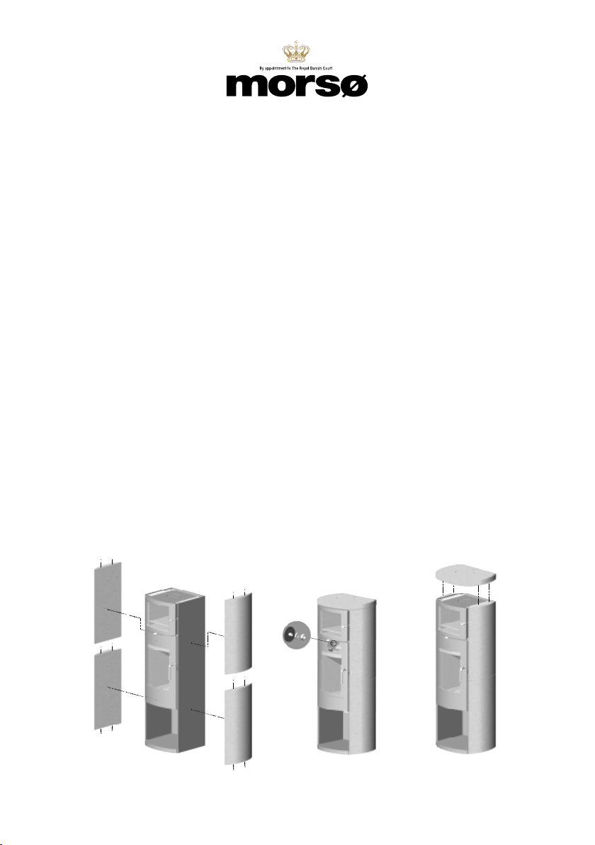
Installazione dei pannelli laterali in steatite sul modello Morsø 8259
La steatite è un materiale morbido di origine naturale che deve essere trattato con particolare cura du-
rante l’installazione della stufa. È consigliabile che l’operazione di installazione dei pannelli laterali in stea-
tite venga eseguita da due persone, al ne di evitare gra o danni accidentali alla stufa. Utilizzare una
livella a bolla d’aria può aiutare a garantire un posizionamento e un’installazione adeguati.
Fase 1: Posizionare la stufa sul pavimento, nel punto di installazione nale. Assicurarsi che la stufa
sia livellata prima di installare i pannelli laterali in steatite.
Fase 2: Rimuovere i paraamma e i pannelli mattonati laterali dal lato interno della stufa. Per ulte
riori dettagli su questa procedura, vedere le istruzioni di installazione e il manuale utente.
Fase 3: Notare le posizioni dierenti dei fori di ssaggio sui pannelli in steatite (Vedere gura). Sono
necessari ssaggi dierenti, a seconda del fatto che il pannello in steatite debba essere
installato sul lato superiore o su quello inferiore.
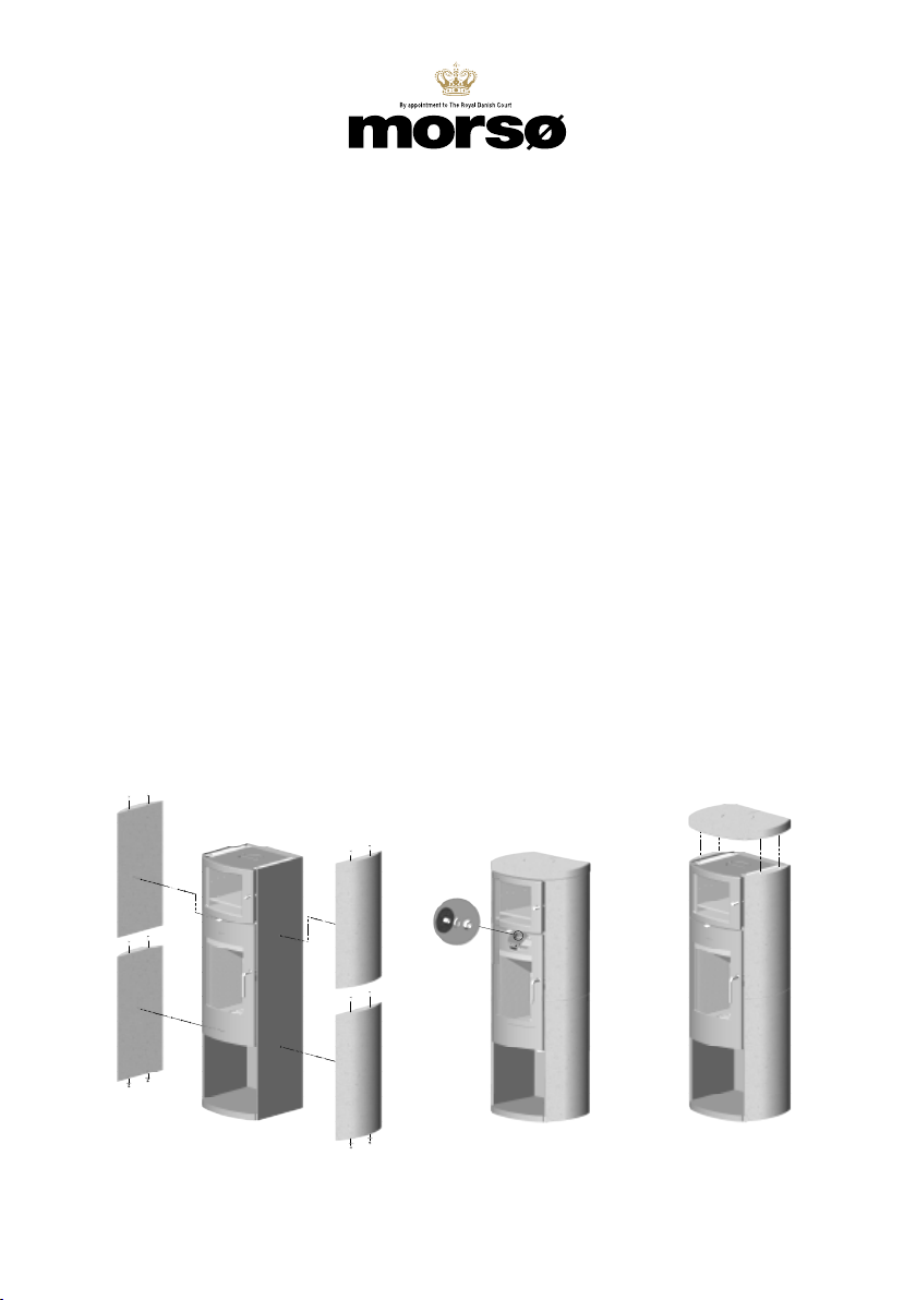
Fase 4: Spingere i quattro tappi in plastica con rondelle in dotazione all’interno dei fori posti
sulato inferiore dei pannelli in steatite inferiori.
Fase 5: Il lato inferiore del pannello in steatite è tenuto in posizione mediante una vite senza testa
con relativa rondella e controdado, posizionata sul lato in acciaio della stufa, sotto la camera
di combustione. Inserire i 2 perni sul lato superiore del pannello laterale inferiore in pietra ,
prima di posizionare il pannello superiore in steatite. Fissare il pannello superiore attraverso
la piastra laterale in ghisa della camera di combustione.
Importante: i pannelli laterali in steatite sono dotati di una boccola lettata preinstallata in
fabbrica. Prestare attenzione a non serrare eccessivamente le viti di bloccaggio in quanto ciò
può causare l’allentamento delle boccole.
Fase 6: Ripetere le procedure specicate nei punti 4 e 5 sul lato opposto.
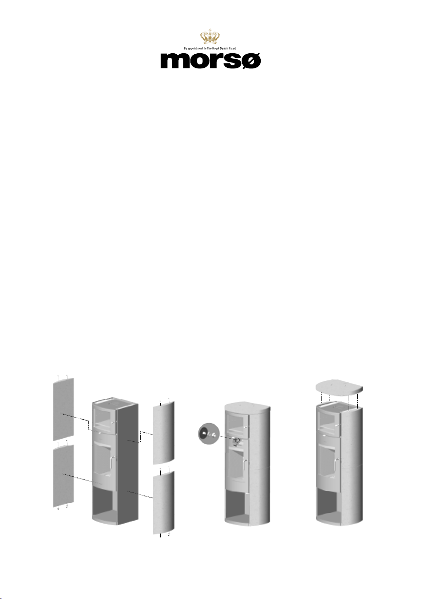
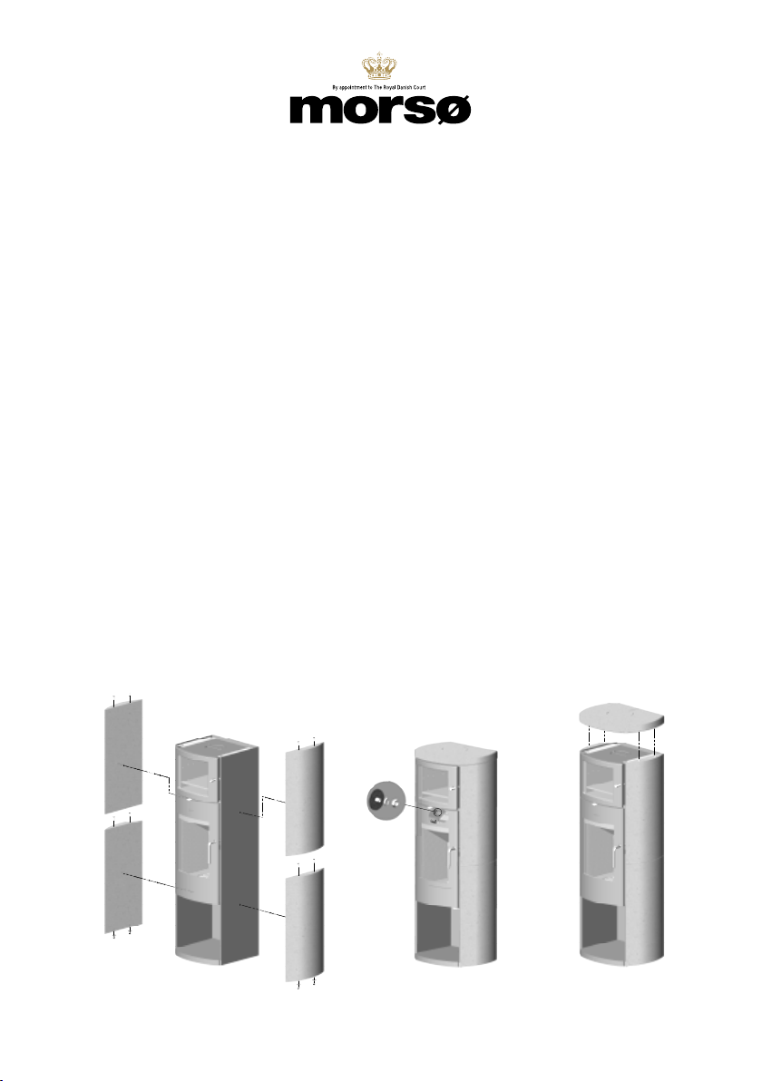
Fase 7: Installare i 4 perni piccoli restanti sul lato superiore dei pannelli laterali superiori in steatite,
prima di procedere al posizionamento della piastra superiore.
Fase 8: Rimontare i pannelli mattonati laterali e i paraamma all’interno della camera di combustio-
ne. Prima di accendere la stufa, assicurarsi che i paraamma e i pannelli mattonati laterali
siano installati correttamente.Se la stufa deve essere dotata di un’uscita posteriore per la
canna fumaria, assicurarsi di installare l’anello fornito in dotazione sotto la pia
stra in steatite allentata presente sul foro della piastra superiore.
Leggere il manuale prima di installare e accendere la nuova stufa.

10
Revisions
Rev.
Sign.:
Title:
Drawing no.:
1:10
Morsø 8229 Bagefag
TOL
04.12..2014
A2
Dimension drawing
329.40
ERROR!:materiale
Date of print: 27-09-2016
C:\Working\8200 Assembly.SLDASM
-
Itemno.:
This drawing is Morsø Jernstøberi A/S' property and must not be sold, lended or copied without any written authorization from the company.
Material:
Weight kg.:
Model no.
Drawingtype:
Location of file:
Scale:
Format:
Released:
Construction:
Date:

1110
Revisions
Rev.
Sign.:
Title:
Drawing no.:
1:10
Morsø 8229 Bagefag
TOL
04.12..2014
A2
Dimension drawing
329.40
ERROR!:materiale
Date of print: 27-09-2016
C:\Working\8200 Assembly.SLDASM
-
Itemno.:
This drawing is Morsø Jernstøberi A/S' property and must not be sold, lended or copied without any written authorization from the company.
Material:
Weight kg.:
Model no.
Drawingtype:
Location of file:
Scale:
Format:
Released:
Construction:
Date:

12
www.morsoe.com
Revisions
Rev.
Sign.:
Title:
Drawing no.:
1:10
Morsø 8229 Bagefag
TOL
04.12..2014
A2
Dimension drawing
329.40
ERROR!:materiale
Date of print: 27-09-2016
C:\Working\8200 Assembly.SLDASM
-
Itemno.:
This drawing is Morsø Jernstøberi A/S' property and must not be sold, lended or copied without any written authorization from the company.
Material:
Weight kg.:
Model no.
Drawingtype:
Location of file:
Scale:
Format:
Released:
Construction:
Date:
MORSØ JERNSTØBERI A/S . DK-7900 NYKØBING MORS
Morsø Jernstøberi A/S - 27.09.2016 - 72816700
Table of contents
Languages:
Other Morsø Stove manuals

Morsø
Morsø 2B Classic 2020 User manual

Morsø
Morsø Air Kit Set User manual

Morsø
Morsø 1410 User manual

Morsø
Morsø S50-40 User manual

Morsø
Morsø 1010 User manual

Morsø
Morsø 6100 Series User manual

Morsø
Morsø 6840 User manual

Morsø
Morsø 7340 User manual

Morsø
Morsø 4400 Series User manual

Morsø
Morsø 1440 User manual
Popular Stove manuals by other brands

RHÉA-FLAM
RHÉA-FLAM LAMIA T manual

Dovre
Dovre 250 Installation instructions and operating guide

Palazzetti
Palazzetti ECOFIRE ISABEL 9 U. S. DESCRIPTION / CLEANING / TECHNICAL DATA

Broseley
Broseley 12B Installation & operating instructions

Comfort Smart
Comfort Smart CS-25IR-BRZ Assembly / care & use instructions

Warmlite
Warmlite WL46001 instruction manual