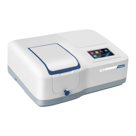
VWR M4 User manual

VWR® M4 Spectrophotometer
Instruction Manual
European Catalogue Number
EU/UK/CH Plug: 634-1087
Version: 1.0.0
Issued: 24, June 2019

Legal Address of Manufacturer
Europe
VWR International bvba
Researchpark Haasrode 2020
Geldenaaksebaan 464
B-3001 Leuven
+ 32 16 385011
http://be.vwr.com
Made in China

Table of Contents
Warning 1
Avoiding Electrical Shock 1
Package Contents 2
Unpacking 2
Installation 2
Intended use 2
Symbols and conventions 2
Product Specifications 2
Overview 3
Description 3
Getting Started 4
Turn On and Self-check 4
Important Guidelines 4
General Operating Instructions 4
Touch Screen Using Tips 4
Select Application 4
Basic Operation 5
Measurement Results Operation 6
Files Operation 7
Calibration and System Settings 8
Performance Verification 11
Operation 13
Photometry 13
Quantitation 15
Spectrum 19
Troubleshooting 21
Repair and maintenance 22
Daily Maintain 22
Spare Parts Replacement 22
User replaceable accessories and spare parts 23
Technical service 23
Warranty 24
Compliance with local laws and regulations 24
Equipment disposal 25
Functions 26
Installation 26
Install and Uninstall VWR Software Multi Wave Pro 26
Run VWR Software Multi Wave Pro 29
Introduction 30
Main Interface 30
Menus Bar and Tools Bar 30

Warning
Avoiding Electrical Shock
Please follow the guidelines below, and read this manual in its entirety to ensure safe operation of the unit.
VWR recommends against the use of M4 Spectrophotometer.
To avoid electrical shock
Do not open the device.
Disconnect the device from the mains supply before carrying out maintenance work or
changing the fuses.
The inside of the device is a high-voltage area Danger!
Do not use the device if it is damaged, especially if the main power cable way is in any
damaged or defective.
Repairs may only be carried out by the service technicians from your local VWR office and
authorized contractual partners.
The device must be connected to a power outlet that has a protective ground connection.
If the equipment is used in a manner not specified by the manufacturer, the protection provided
by the equipment may be impaired.
Avoiding Damage to the Instrument
Do not allow any liquid to enter into the device.
Do not operate the device in a hazardous location or potentially explosive environment.

Package Contents
Description
Quantity
Catalogue-No
Spectrophotometer
1PC
634-1087
Glass Cuvette
4PCS
634-6013
Quartz Cuvette
2PCS
634-6018
Power Cord ( Euro Plug )
1PC
on request
Power Cord ( UK Plug )
1PC
on request
Power Cord ( CH Plug )
1PC
on request
Software CD-ROM
1PC
N/A
USB Cable
1PC
N/A
Instruction Manual
1PC
N/A
Dust Cover
1PC
on request
Unpacking
Open the package, according to carefully check the packaging packing list items, if found inside the packaging are
missing or damaged items please contact your local VWR office and authorized contractual partners.
Installation
Placement
Place the instrument on the stable table carefully.
Install printer (Optional)
Check to confirm instrument power switch is turned off, connect the printer’s data cable to the Instrument’s
serial/USB port.
Connect the power cord
Check to confirm instrument power switch is turned off, the power cord plug into two separate power interface and
power supply socket apparatus.
Intended use
For research use only. Not intended for any animal or human therapeutic or diagnostic use.
Symbols and conventions
The following chart is an illustrated glossary of the symbols that are used in this manual.
CAUTION This symbol indicates a potential risk and alerts you to proceed with caution^
CAUTION This symbol indicates the presence of high voltage and warns the user to proceed
with caution
CAUTION This symbol indicates risks associated with hot surfaces
Product Specifications
Optical System
Spilt Beam
Wavelength Range
190-1100nm
Band Width
2nm
Stray Light
≤0.08%T @ 220nm & 360nm
Photometric Range
0 to 200%T, -0.3 to 3.0A, 0 to 9999C
Wavelength Accuracy
±0.5nm
Photometric Accuracy
±0.4%T or ±0.004A @ 1A
Stability
0.002A/h @ 500nm

Memory
236KB
Language
English, French, German, Spanish, Portuguese, Chinese
Display
TFT Colour LCD (5”, Touch Screen)
Interface
USB-A, USB-B,RS-232
Measuring Procedure
Photometry, Quantitation, Spectrum Scan
Power Supply
AC 100~240 V, 50~60 Hz
Dimension
456×360×185
Weight
10.5kg
Work Environment
15 to 35℃, 15 to 70% relative humidity
Store Environment
-10 to 50℃, 15 to 70% relative humidity
This instrument is compliant to the European Directives on Low Voltage Directive 2014/35/EU,
Electromagnetic compatibility 2014/30/EU.
Restriction on use of Hazardous Substances RoHS 2011/65/EU and their amendments.
Overview
M4 Spectrophotometer used in Chemistry, Pharmaceuticals, Biochemical, Metallurgy, Light Industry, Textile,
Material, Environments, Medical, Education and some other fields for Quality Control laboratories.
Description
Front View
Touch
screen
Lid of the
Compartment
Pull Rod
Lid of Lamp
Room
Right View
USB Port
(for USB Disk/
USB Printer)
Power
Switcher
Rear View

Fuse Seat
Power
Socket
Print Port
USB Port
(for PC)
Getting Started
Turn On and Self-check
Switch on the power. Self-check includes the following steps: Turn On Lamp → Locating Filter Disc → Locating
Automatic Sample Holder (If Installed) → Get Dark Current → Locating Wavelength → Check Energy → Check
System baseline.
Important Guidelines
Reagents and dilution buffers can cause cauterization and other damage to health.
Samples (nucleic acids, proteins, bacteria cultures) can be infectious and cause serious damage to
health.
During sample preparation, measuring procedures and maintenance and cleaning work, observe all local
laboratory safety precautions (e.g. wear protective clothing and gloves, use of disinfectant) regarding the
handling of sample material.
Dispose of measuring solutions and cleaning and disinfectant materials in accordance with the relevant
local laboratory regulations.
General Operating Instructions
Touch Screen Using Tips
The entire screen can be started with a touch. To make a choice, use your nails, fingertips, pencil, or stylus to
press the screen. Don't press the screen with sharp objects (such as ball point).
Select Application
Main Interface, press the icon to select application.
Photometry Measure the absorbance or transmittance of the sample.
Quantitation Establish the standard curve and measure the concentration of the sample.
Spectrum Scan the sample in a wavelength range.
File Manage files stored in the instrument or USB disk.
System System calibration and setup.
Performance verification Verify the performance of the instrument.
Basic Operation
Home Back to main interface.
Return Back to the previous interface.
/
Page Up/Down Go to previous/next page.

Measurement Results Operation
Open Open result(s) from internal/USB memory.
Save Save result(s) to internal/USB memory.
Print Print result(s).
Delete Delete selected result(s).
Rename, Print and Delete Results
Rename a Sample:
List interface, press the area Name, key in the sample name (Up to
8 characters).
Print the Measurement
Report:
List interface, press the icon .
Delete sample(s):
List interface, press the Check Box, and press the icon .
Open Results
Open:
1. List interface, press the icon .
2. Press the icon internal memory/USB memory to select the
memory which the file saved.
3. Press file lists to select, press the button Open.

Save Results
Save:
1. List interface, press the icon Save.
2. Press the icon / to select the Internal/USB memory
which the file to save.
3. Type in the file name, press the button Save.
Files Operation
Internal Memory Internal memory of the spectrophotometer.
USB Memory USB extended mass memory.
Copy Copy the selected file(s) from internal /USB memory to USB/internal memory.
Export csv Export file(s) To *.csv format
Export txt Export file(s) To *.txt format
Delete Delete the selected file(s).
Rename, Import, Export and Delete Files
Rename a File:
File management interface, press the area Name, key in the file
name (Up to 8 characters).

Copy File(s) From/To
Internal Memory/USB
Memory:
File management interface, press the Check Box, press the button
(Need USB disk).
Export File(s) To *.csv
Format
File management interface, press the Check Box, press the button
(Need USB disk).
Export File(s) To *.txt
Format
File management interface, press the Check Box, press the button
(Need USB disk).
Delete File(s):
File management interface, press the Check Box, and press the
icon .
Calibration and System Settings
Select the icon in the main interface. Display options to calibrate the system and configure the basic
instrument settings.
Calibration
Calibrate Start to do calibration.
Select Tab Calibration in the System interface. Remove something in the measurement channel, close the
sample chamber cover, select the item Dark current, Wavelength or System baseline, press the icon to
do calibration.
Settings of Light Source
Select Tab Light source in the System interface. The light source information is displayed on the screen.

Edit Clock
Accept Accept the new value.
Select Tab Clock in the System interface. Press the value of year, month, date, hour, minute or second to change.
Press the icon to accept new value.
Memory Management
Format Internal Memory Format the internal memory of the spectrophotometer.
Format USB Memory Format the USB mass storage.
Select Tab Memory in the System interface. The use of the internal and USB memory (If inserted) are show. Press
the icon / to format internal memory/USB memory.

Language Selection
Accept Accept the new language.
Select Tab Language in the System interface. Select a language, press the icon to change.
General Options
Select Tab General Options in the System interface.
Beep:
Press the icon to turn on/off the beep.
Brightness:
Press the icon / to decrease/increase the brightness of
the LCD display.
Close display:
Press the icon to turn on/off. If turned on, the display will
close automatically if no operation for 30 minutes.
Sample holder:
If you have a new automatic sample holder installed, you need to set
the sample holder type by pressing the icon
/ (AC-5: 5 cells automatic sample holder, AC-8:8 cells
automatic sample holder).

Restore Defaults
Restore Restore the parameters to factory settings.
Select Tab Restore defaults in the System interface. Select an item, press the icon to restore.
Performance Verification
Select the icon in the main interface. Display options to verify the performance of the instrument.

Important information Before verifying the performance, the instrument needs to be
preheated for 30 minutes, and then re-measure dark current.
Verifying Wavelength Accuracy and Wavelength Repeatability
Select Tab Wavelength accuracy in the Performance verification interface.
Standard Sample:
Holmium oxide solution or equivalent filter
Measurement:
1. Remove something in the measurement channel, close the sample
chamber cover, press the wavelength value, type in the wavelength of
measurement, press the button Zero;
2. Put the Standard Sample in the measurement channel, press the
button Measure;
3. Repeat step 2 to do measurement three times. The difference between
the average of the three measurements and the standard value is the
single-point wavelength tolerance. The difference between the
maximum and minimum values of the three measurements is single
point wavelength repeatability;
4. Repeat step 1-3 to do measurement single-point wavelength tolerance
one by one. The maximum value in the single-point wavelength
tolerance is wavelength accuracy. The maximum value in the single-
point wavelength reproducibility is wavelength repeatability.
Verifying Photometric Accuracy and Photometric Repeatability
Select Tab Photometric accuracy in the Performance verification interface.
Standard Sample:
NIST 930D or equivalent filter
Measurement:
1. Remove something in the measurement channel, close the sample
chamber cover, press the wavelength value, type in the wavelength of
measurement, press the button Zero;
2. Put the Standard Sample in the measurement channel, press the
button Measure;
3. Repeat step 2 to do measurement three times. The difference between
the average of the three measurements and the standard value is the
single-point photometric tolerance. The difference between the
maximum and minimum values of the three measurements is single
point photometric repeatability;
4. Repeat step 1-3 to do measurement single-point photometric tolerance
one by one. The maximum value in the single-point photometric
tolerance is photometric accuracy. The maximum value in the single-
point photometric reproducibility is photometric repeatability.
Verifying Stray Light
Select Tab Stray light in the Performance verification interface.

Standard Sample:
10g/L NaI solution or equivalent filter (220nm), 50g/L NaNo2 solution
or equivalent filter (340 or 360nm)
Measurement:
1. Remove something in the measurement channel, close the sample
chamber cover, press the wavelength value, type in the wavelength of
measurement;
2. Put the Reference in the measurement channel, press the button Zero;
3. Put the Standard Sample in the measurement channel, press the button
Measure, the result is the stray light of this wavelength.
Verifying Noise (0A)
Select Tab Noise (0A) in the Performance verification interface.
Standard Sample:
None
Measurement:
1. Remove something in the measurement channel, close the sample
chamber cover, press the wavelength value, type in the wavelength 500,
press the button Zero;
2. Press the button Measure, the result is the noise of this wavelength.
Verifying Noise (0%T)
Select Tab Noise (0%T) in the Performance verification interface.
Standard Sample:
Block
Measurement:
1. Remove something in the measurement channel, close the sample
chamber cover, press the wavelength value, type in the wavelength 500,
press the button Zero;
2. Put the Block in the measurement channel, press the button Measure,
the result is the dark noise of this wavelength.
Verifying Stability
Select Tab Noise in the Performance verification interface.
Standard Sample:
None
Measurement:
1. Remove something in the measurement channel, close the sample
chamber cover, press the wavelength value, type in the wavelength 500,
press the button Zero;
2. Press the button Measure, the result is the noise of 500nm.
Verifying Bandwidth
Select Tab Dark Bandwidth in the Performance verification interface.
Standard Sample:
Low pressure quartz mercury lamp
Measurement:
1. Open the lamp cover, put the low pressure quartz mercury lamp into the
lamp seat, and turn it on.
2. Remove something in the measurement channel, close the sample
chamber cover, press the wavelength value, type in the wavelength 546.1;
3. Press the button Measure, the result is the bandwidth.
Operation
Important information The cuvettes must be clear and there’s no remains of the
samples on the surface of it. Only Silicon (Quartz) cuvettes are permitted to be used in the range of
UV area.
Photometry
Photometry mode is used to measure the absorbance or transmissivity of the sample.

1. Main interface, press the icon to start a Photometry application.
Mode Switch measurement mode to %T, Abs or Energy.
Wavelength Set measurement wavelength.
Zero Do 0Abs/100%T.
Read Measure sample and record the result.
List View the result(s) list.
Increase/Decrease Increase/Decrease the gain of signal. Only for Energy mode.
2. Press the icon to switch to the measurement mode.
Abs
Measure absorbance value of the sample(s).
%T
Measure transmittance value of the sample(s).
E
Measure energy value of the sample(s).
3. Press the icon to set wavelength, key in the measurement wavelength.
4. Put the reference in the measurement channel, press the icon to do zero.
5. Put the sample in the measurement channel, press the icon to measure a sample and record the result.
6. Press the icon to browse the result(s).

Quantitation
Quantitation mode is used to measure the concentration of the sample(s).
1 Main interface, press the icon to start a Quantitation application.
2 Establish Method
2.1 Quantitation interface, press the button Establish method.
Measurement
A=A1: Absorbance is equal to the measured absorbance value of the
measured wavelength 1

A=A1-m*A2: Absorbance is equal to the difference between the
absorbance value of the measured absorbance at the wavelength 1 and the
wavelength 2, m is the Coefficient
A=A1/A2: Absorbance is equal to the ratio of the measured absorbance
value of the measured wavelength 1 and 2
Wavelength 1
Measurement wavelength 1
Wavelength 2
Measurement wavelength 2
Fitting
LIN-0: Linear to zero
LIN: Linear.
QUA: Quadratic.
Unit
- (No Unit), %, ppm, ppb, g/L, mg/L, μg/L, ng/L, g/dL, mg/dL, μg/dL, mg/mL,
μg/mL, ng/mL, μg/μL, ng/μL, mol/L, mmol/L, IU, Custom(User input, Up to 8
characters).
Calibration
Coe K: Input equation coefficient.
Std M: Measure standard sample(s)
Std I: Input standard sample(s)
Standard quantity
Standard sample number (Up to 10)
2.2 Press the item to set measurement parameters.
2.3 After all the parameters are set up, press the button Next to start establishing the standard curve. If the
item Calibration is set to the parameter Coe K, Std M or Std I, please refer to 2.3.1, 2.3.2 or 2.3.3.
2.3.1 Input equation coefficient to establish standard curve.
(1) Input equation coefficient K0 ~ K3. Press button Next.
2.3.2 Measure standard sample to establish standard curve
(1) Put the reference in the measurement channel, press the button Zero to do zero.
Other manuals for M4
1
Table of contents
Other VWR Measuring Instrument manuals

VWR
VWR PH-130 User manual

VWR
VWR avantor PH-2500L User manual

VWR
VWR DO-230 User manual

VWR
VWR P2 Series User guide

VWR
VWR avantor CO 3100 H User manual

VWR
VWR MD 8000 L User manual

VWR
VWR avantor PH-2500L User manual

VWR
VWR MCT 100 User manual

VWR
VWR VisiScope 260 Series User manual

VWR
VWR Avantor MU 6100 L User manual