Motrona AX 342 User manual

AX34209a_e.doc / Mrz-16 Page 1 / 38
AX 342
Process Indicator with 2 Analogue Inputs,
2 Presets, Relay Outputs and
Serial RS232 / RS485 Interface
Two analogue inputs with independent scaling, each +/- 10V or 0/4 –20 mA
Operating modes for display of input A or input B or the combinations
[A + B], [A - B], [A x B] and [A : B]
Useful supplementary functions like Tare function, programmable averaging
functions, programmable linearization etc.
Aux. output 24 V DC / 100 mA for sensor supply
Operating Instructions

AX34209a_e.doc / Mrz-16 Page 2 / 38
Safety Instructions
This manual is an essential part of the unit and contains important hints about
function, correct handling and commissioning. Non-observance can result in
damage to the unit or the machine or even in injury to persons using the
equipment!
The unit must only be installed, connected and activated by a qualified electrician
It is a must to observe all general and also all country-specific and application-
specific safety standards
When this unit is used with applications where failure or mal-operation could cause
damage to a machine or hazard to the operating staff, it is indispensable to meet
effective precautions in order to avoid such consequences
Regarding installation, wiring, environmental conditions, screening of cables and
earthing, you must follow the general standards of industrial automation industry
- Errors and omissions excepted –
General instructions for cabling, screening and grounding can be found in the
SUPPORT section of our website http://www.motrona.com
Version:
Description:
AX34209a/tj/hk/05_2011
First edition

AX34209a_e.doc / Mrz-16 Page 3 / 38
Table of Contents
1. Introduction..........................................................................................................................................4
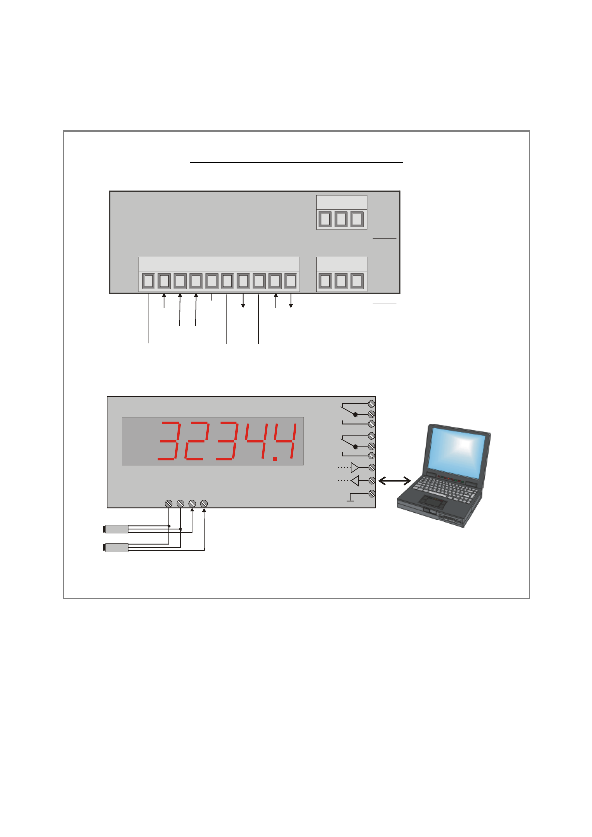
2. Electrical Connections..........................................................................................................................5
2.1. Power supply ................................................................................................................................6
2.2. Aux. voltage output ......................................................................................................................6
2.3. Analogue measuring inputs..........................................................................................................6
2.4. Relay Outputs ...............................................................................................................................6
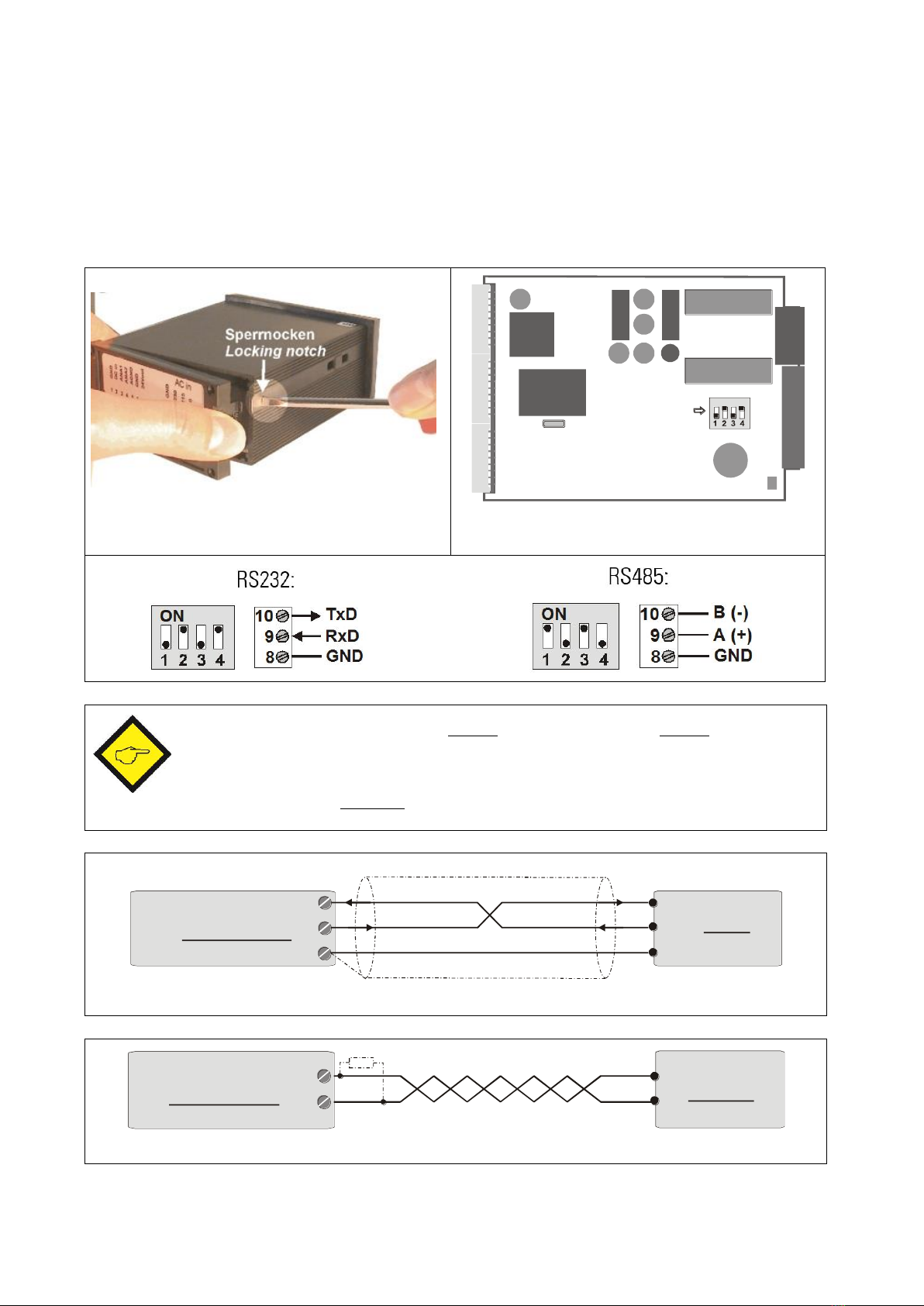
2.5. Serial RS232 / RS485 interface (AX 348 only).............................................................................7
3. Jumper settings ...................................................................................................................................8
4. How to Operate the Keys ...................................................................................................................10
4.1. Normal display state ..................................................................................................................10
4.2. Parameter settings .....................................................................................................................11
4.3. Teach operation..........................................................................................................................12
4.4. Set all parameters to “Default“ .................................................................................................12
4.5. Code Locking of the Keypad.......................................................................................................12
5. The Parameter Menu .........................................................................................................................13
5.1. Overview of Basic Parameters: ..................................................................................................13
5.2. Overview of Operational Parameters.........................................................................................14
6. Setting of Parameters ........................................................................................................................ 15
6.1. Basic Parameters........................................................................................................................15
6.2. Operational parameters..............................................................................................................16
6.3. Modes of operation ....................................................................................................................17
6.4. Additional settings for the Preselections and Relays................................................................20
6.5. Parameters for the Serial Interface............................................................................................23
7. Commissioning...................................................................................................................................27
8. Special Functions...............................................................................................................................28
8.1. Tare / Offset function .................................................................................................................28
8.2. Linearization ...............................................................................................................................28
8.3. Manual input or „Teaching“ of the interpolation points ...........................................................30
8.4. Overflow and Underflow Control ...............................................................................................32
9. Technical Appendix............................................................................................................................33
9.1. Parameter Lists...........................................................................................................................33
9.2. Dimensions .................................................................................................................................35
9.3. Technical data ............................................................................................................................36
9.4. Commissioning Form ..................................................................................................................37

AX34209a_e.doc / Mrz-16 Page 4 / 38
1. Introduction
Some of the general demands to an up-to-date process controller for automation industry are
always high flexibility, combined with easy and simple operability.
Many applications require two separate analogue inputs for use with single or combined
operation.
Also it may be important to display and evaluate both, linear and non-linear analogue inputs at
an acceptable accuracy, which requires programmable linearization functions.
Process controllers of series AX 342 have been designed for this kind of requirements.
Moreover, these units also provide 2 programmable presets with relay outputs and a serial
RS232 / RS485 interface.

AX34209a_e.doc / Mrz-16 Page 5 / 38
2. Electrical Connections
Terminal assignments and wiring example
GND
17-30VCDIN
1 2 3 4 5 6 7 8 9 10
InputA
+24VDCOUT
TXD/B(-)
RXD/A(+)
GND
GND
1 2 3
1 2 3
X1 X2
X3
C NO NC
C NO NC Rel. 1
Rel. 2
GNDanalogue
InputB
Rel. 2
Rel. 1
TxD
RxD
GND
+
-
A
B
C
NC
NO
C
NC
NO
*)
RS232
Sensor 1
Sensor 2
*) Contact positions are shown in powerless state

AX34209a_e.doc / Mrz-16 Page 6 / 38
When earthing any of the GND terminals, please be aware that all terminals marked
GND or AGND will be earthed.
Multiple earthing on different positions of an installation may cause problems,
especially with poor overall performance of the whole earthing and screening system!
The minus potential of analogue inputs is internally connected to the minus of the DC
supply. When you like to loop current signals through several units, it is therefore
necessary to supply each unit from a separate, potential-separated DC source.
2.1. Power supply
The unit operates from a DC power with 17 to 30 VDC applied via terminals 1 and 2. The
consumption depends on the level of the supply voltage (typical 80 mA at 30V or 130mA at 17V,
plus current taken from the aux. output).
2.2. Aux. voltage output
Terminal 7 provides an auxiliary output of 24 V DC / 100 mA max. for supply of sensors and
encoders. This voltage is independent from the level of the input voltage.
2.3. Analogue measuring inputs
There are two analogue inputs with common minus potential available (Input A and Input B).
Both refer to the AGND potential of terminal 5 which is internally connected to terminals 1, 6
and GND.
The analogue inputs can be configured for voltage input (+/- 10 V) or current input
(0/4 –20 mA) by means of internal jumpers.
Ex factory, both inputs are always configured for current input.
(see section 3 for jumper settings)
2.4. Relay Outputs
The two output relays provide individually programmable switching characteristics. It is
recommended to use additional filter components for external coils when switching inductive
loads. The switching capability of the dry relay contacts is either 250 VAC / 1 A / 250 VA
or 100 VDC / 1 A / 100 W
The relays operate with a typical delay time of 60 ms (see chapter Fehler! Verweisquelle
konnte nicht gefunden werden.)

AX34209a_e.doc / Mrz-16 Page 7 / 38
2.5. Serial RS232 / RS485 interface (AX 348 only)
Ex factory the unit is set to RS232 communication. This setting can be changed to RS485
(2-wire) by means of an internal DIL switch. To access the DIL switch, you must remove the
screw terminal connectors and the backplane. Then pull the board to the rear to remove the
PCB from the housing.
ON
DIL-Switch
Removal of the back plane
Location of the DIL switch
Never set DIL switch positions 1 and 2 or DIL switch positions 3 and 4 to “ON”
at the same time!
After setting the switch, shift the print carefully back to the housing and avoid
damage of the front pins for connection to the front keypad plate.
2
3
5
RxD RxD
TxDTxD
GND
Screen
PC
AX 342 9
(Sub-D-9)
10
8
Connection of the RS232 interface
PLC
AX 342 9
10
A(+)
B(-)
A(+)
B(-)
Connection of the RS485 interface

AX34209a_e.doc / Mrz-16 Page 8 / 38
3. Jumper settings
When your input signal is a current of 0-20 mA or 4-20 mA, there is no need to change jumper
settings and you can skip this section.
Where however you intend to use one or both inputs for voltage signals, you must change the
internal jumper settings correspondingly.
To access the jumpers, you have to disconnect the rear screw terminal strips, remove the back
plane from the unit and pull the PCB out of the housing
=jumper inseredscrew terminal strip
locking tab
factory preset
A=current, B =current
A = voltage, B = voltageA = voltage, B = currentA = current, B = voltage
A
(mA) (V) B
(mA) (V)
A
(mA) B
(mA)
A
(mA) (V) A
(mA) (V)
A
(mA) (V)
B
(mA) (V) B
(mA) (V)
B
(mA) (V)
A
(mA) A
(mA)
A
(mA)
B
(mA) B
(mA)
B
(mA)
Wrong jumper settings may cause serious damage to the unit!
After setting the jumpers, please shift the print carefully back to the housing, in order not
to damage the front pins for connection to the keypad plate.

AX34209a_e.doc / Mrz-16 Page 9 / 38
Current inputs are automatically scaled to an input range of 0/4 –20 mA.
Voltage inputs use the standard range of +/- 10V.
You are free to measure voltages up to 120 volts DC by use of a remote resistance in series to
the input line (please observe applicable safety standards!). You can calculate the value from
the formula
Rx [ k] = 3 x Vx [ V ] - 30
R = resistance value
V = input voltage
Example: Desired input = 100 volts:
R = [ 3 x 100 ] –30 (k) = 270 k
With regard to the scaling procedure described later, the new maximum input with resistance
will work like a 10 volts signal with no resistance

AX34209a_e.doc / Mrz-16 Page 10 / 38
4. How to Operate the Keys
The unit uses 3 front keys for all setup operations. Subsequently, the key functions will be
named as shown in the table below.
ENTER
SET
Cmd
(Command)
The functions of the keys are depending on the actual operating state of the unit.
The following three operating states apply:
Normal display state
Setup state
a.) Basic setup
b.) Operational parameter setup
Teach operation
4.1. Normal display state
You can change over to the other states while the unit is in the normal display state only.
Change over to
Key operation
Basic setup
Keep ENTER and SET down simultaneously for 3 seconds
Operational
parameter setup
Keep ENTER down for 3 seconds.
Teach operation
Keep SET down for 3 seconds
The Cmd key is only used for execution of the Tare function, the Reset function and for
Teaching the interpolation points for linearization (see section 8).

AX34209a_e.doc / Mrz-16 Page 11 / 38
4.2. Parameter settings
4.2.1. How to select a parameter
The ENTER key will scroll through the menu. The SET key allows to select the corresponding
item and to change the setting or the numeric value. After this, the selection can be stored by
ENTER again, which automatically changes over to the next menu item.
4.2.2. How to change parameter settings
With numerical entries, at first the lowest digit will blink. When keeping the SET key down, the
highlighted digit will scroll in a continuous loop from 0 … 9 … 0 … 9. When you release the
SET key, the actual digit will remain and the next digit will be highlighted (blink).
This procedure allows setting all digits to the desired values. After the most significant digit
has been set, the low order digit will blink again and you can do corrections if necessary.
With signed parameters, the high order digit will only scroll between the values “0” (positive)
and “-“ (negative)
4.2.3. How to store settings
To store the actual setting, press the ENTER key, which will also automatically scroll forward
the menu.
The unit changes from programming mode to normal operation when you keep down the ENTER
key again for at least 3 seconds.
4.2.4. Time-out function
The “time-out” function will automatically conclude every menu level, when for a break period
of 10 seconds no key has been touched. In this case, any entry which has not been confirmed
by ENTER yet would remain unconsidered.

AX34209a_e.doc / Mrz-16 Page 12 / 38
4.3. Teach operation
The Time-out function will be switched off during all Teach operations
Key
Function
ENTER will conclude or abort any Teach operation in progress
SET function is fully similar to normal set-up operation
Cmd will store the display value to the register and will change over to the
next interpolation point.
For details of the Teach procedure see section 8.3.
4.4. Set all parameters to “Default“
At any time you can return all settings to the factory default values.
The factory default settings are shown in the parameter listings in section 6.
When you decide to set all parameters to „default“, please be aware that all
previous settings will be lost and you will need to do the whole set-up
procedure once more
To execute the „Default“ setting function:
Power the unit down.
Press the ENTER key.
Power the unit up again while the ENTER key is kept down
4.5. Code Locking of the Keypad
When the code locking of the keypad has been switched on, any key access first results in
display of
To access the menu you must press the key sequence
within 10 seconds, otherwise the unit will automatically return to the normal display mode.

AX34209a_e.doc / Mrz-16 Page 13 / 38
5. The Parameter Menu
The menu provides one section with “basic parameters” and another section with “operational
parameters”. On the display you will only find those parameters which have been enabled by
the basic settings. E.g. when the Linearization Functions have been disabled in the basic set-up,
the associated linearization parameters will also not appear in the parameter menu.
All parameters, as good as possible, are designated by text fragments. Even though the
possibilities of forming texts are very limited with a 7-segment display, this method has proved
to be most suitable for simplification of the programming procedure.
The subsequent table is to show the general structure of the whole menu only.
Detailed descriptions of all parameters will follow in section 6.
5.1. Overview of Basic Parameters:
General:
Mode of operation
Brightness of the display
Update time of the display
Access code
Mode of linearization
Definition of command key function
Preselections:
Signal source of relay 1
Switching characteristics of relay 1
Signal source of relay 2
Switching characteristics of relay 2
Hysteresis of relay 1
Hysteresis of relay 2
Communication:
Serial unit number
Serial communication format
Serial baud rate

AX34209a_e.doc / Mrz-16 Page 14 / 38
5.2. Overview of Operational Parameters
Single Mode
Dual Mode
Combined Modes
Setpoints
Preselection 1
Preselection 2
Display and
„inPutA"
„inPutA"
„inPutA"
Scaling
„StArtA"
„StArtA"
„StArtA"
„End A"
„End A"
„End A"
„dPoi A"
„dPoi A"
„dPoi A"
„FiLt A"
„FiLt A"
„FiLt A"
"OFFS A" *)
"OFFS A" *)
„inPutb"
„inPutb"
„StArtb"
„StArtb"
„End b"
„End b"
„dPoi b"
„dPoi b"
„FiLt b"
„FiLt b"
OFFS b" *)
„n) FAc"
„d FAc"
„P FAc"
„dPoint"
Interface
Serial Timer
Serial Mode
Serial Code
Linearization
P01_H **)
P01_Y **)
…
P16_H **)
P16_Y **)
*) appears only when the Offset function has been enabled
**) appears only when the linearization is switched on

AX34209a_e.doc / Mrz-16 Page 15 / 38
6. Setting of Parameters
6.1. Basic Parameters
In general, the parameters described subsequently must be set with the very first
commissioning of the unit only. For best comprehensibility, this section describes setup of all
display functions only first. Settings applicable to relay outputs and serial interface are
described separately.
Keep ENTER and SET down simultaneously for 3 seconds to access the basic parameters.
Menu Text
Default
Mode of operation
Single input operation (input A only)
Dual input operation (input A and input B separately)
Sum operation (input A + input B)
Differential operation (input A –input B)
Dividing operation (ratio A : B)
Multiplying operation (product A x B)
Brightness of the display
„100“
„ 100“
100% of maximum brightness
„ 80“
80% of maximum brightness
„ 60“
60% of maximum brightness
„ 40“
60% of maximum brightness
„ 20“
20% of maximum brightness
Update time of the display
„0.300“
Updates the display every x.xxx seconds. Setting range from
0.050 to 5.999 seconds.
Keypad interlock code
Keypad enabled continuously
Keypad locked for any access
Keypad locked, except for access to preselections
Pres 1 und Pres 2
Mode of linearization
No linearization. The corresponding parameters will
not appear in the menu.
Linearization for the numeric range 0 –99999.
Interpolation points to be set in the positive range
only (negative values will appear as a mirror).
Linearization over the full range
–99999 to +99999

AX34209a_e.doc / Mrz-16 Page 16 / 38
Menu Text
Default
Command key enable
The Command key is switched off and no Offset
values will appear in the menu
The Cmd key will execute the Tare/Offset function
The Cmd key will execute the Teach function
The Cmd key will execute both, the Tare and the
Teach function
6.2. Operational parameters
After the basic setup, you can access the operational parameters by pressing ENTER for at
least 3 seconds. You will only find those parameter texts that are relevant for your mode of
operation.
To exit the menu, keep again ENTER down for at least 3 seconds, or just wait for the automatic
Time-Out function.

AX34209a_e.doc / Mrz-16 Page 17 / 38
6.3. Modes of operation
6.3.1. Single mode (input A only)
Menu Text
Setting Range
Default
Input A range
Set the desired range for input A
Voltage +/-10V
Current 0-20 mA
Current 4-20 mA
Start value A
Value which the unit will display with a
zero input signal of 0 volts or 0/4 mA
-99999 … 99999
0
End value A
Value which the unit will display with a
full scale input of 10 volts or 20 mA
-99999 … 99999
1000
Decimal point for signal A
Select the desired position of the decimal point
00000.0
000000
No decimal point
00000.0
one decimal position
---->
0.00000
five decimal positions
Average filter input A
Adjustable floating average filter for smoothing
the display with unsteady input signals
No filtering
2,4,8,16
Number of floating averaging
cycles
Offset value for input A *)
Offset value for the zero displacement of input
A signals
-99999 … 99999
0
*) When the Tare function is switched on only

AX34209a_e.doc / Mrz-16 Page 18 / 38
6.3.2. Dual Mode (Inputs A and B separately)
A
B
With this mode, the SET key selects between display of channel A
and display of channel B, and the bar of the high order LED
indicates which of the two channels is actually in display.
Menu Text
Input Range
Default
Input B range
Set the desired range for input B
Voltage +/-10V
Current 0-20 mA
Current 4-20 mA
Start value B
Value which the unit will display with a
zero input signal of 0 volts or 0/4 mA
-99999 … 99999
0
End value B
Value which the unit will display with a
full scale input of 10 volts or 20 mA
-99999 … 99999
1000
Decimal point for signal B
Select the desired position of the decimal
point
000000
000000
No decimal point
00000.0
one decimal position
---->
0.00000
five decimal positions
Average filter input B
Adjustable floating average filter for
smoothing the display with unsteady input
signals
No filtering
2,4,8,16
Number of floating averaging
cycles
Offset value for input B *)
Offset value for the zero displacement of
input A signals
-99999 … 99999
0
*) When Tare function is switched on only

AX34209a_e.doc / Mrz-16 Page 19 / 38
6.3.3. Combined Modes [A + B], [A - B], [A : B], [A x B]
These modes allow displaying either the single channels A and B or the calculated result
according to the selected combination. The SET key allows scrolling between the three
displays.
A
B
<AB>
The upper bar of the high order digit indicates that you display
channel A.
The lower bar of the high order digit indicates channel B.
When no bar is lit, the display shows the result of the calculation,
according to the combination set.
When you use one of the combined modes, you will first have to do the same settings as with
the “Dual” mode for individual display of inputs A and B.
The combined display will then be the result calculated from both single values.
The following additional parameters provide a final scaling facility, so you can read out the
result of your combination in proper engineering units:
Menu Text
Setting Range
Default
Proportional Scaling Factor
Multiplies the result by this setting
-10000 … 10000
1000
Reciprocal Factor
Divides the result by this setting
1 … 99999
1000
Additive Constant
Adds or subtracts this setting
-99999 … 99999
0
Decimal Point
Sets the decimal point for the combined
display value
000000
000000
No decimal point
00000.0
one decimal position
---->
0.00000
five decimal positions
Calculation Formula:
Final display value =value calculated from [A*B] xm_Fac
d_Fac +/- P_Fac

AX34209a_e.doc / Mrz-16 Page 20 / 38
6.4. Additional settings for the Preselections and Relays
6.4.1. Basic settings:
The basic setup menu provides the following additional parameters which are relevant for the
operation of the presets and relays only:
Menu Text
Setting Range
Default
Signal source of Relay 1
Relay 1 depends on analogue input A
Relay 1 depends on analogue input B *)
Relay 1 depends on the combination [A,B] of both
analogue inputs **)
Relay 1 switching characteristics
Greater/Equal:
Relay is statically active with display
greater or equal Preset.
Lower/Equal:
Relay is statically active with display
lower or equal Preset.
Greater/Equal:
Relay is dynamically active with
display greater or equal Preset.
(timed output impulse)
Lower/Equal:
Relay is dynamically active with
display lower or equal Preset.
(timed output impulse)
Signal source of Relay 2
Relay 2 depends on analogue input A
Relay 2 depends on analogue input B *)
Relay 2 depends on the combination [A,B] of both
analogue inputs **)
*) Requires Analogue input B to be activated (i.e. operating mode setting "Dual" or "Combined")
**) Requires operating mode setting "Combined"
Table of contents
Other Motrona Measuring Instrument manuals

Motrona
Motrona IX348 User manual

Motrona
Motrona DS230 Series User guide

Motrona
Motrona AX320 User manual

Motrona
Motrona touchMATRIX PN350 User manual

Motrona
Motrona AX 345 User manual

Motrona
Motrona AX020 User manual

Motrona
Motrona MS 640 User manual

Motrona
Motrona DX350 User manual

Motrona
Motrona SD Series User manual

Motrona
Motrona touchMATRIX DP350 User manual
Popular Measuring Instrument manuals by other brands

TRIATEK
TRIATEK DDN-SW1 install guide

Huawei
Huawei SUN2000 Series user manual

DOLD
DOLD RN 5897/240 Translation of the original instructions

IML
IML IML-RESI F Series Instructions for use

RKC INSTRUMENT
RKC INSTRUMENT AE500 Communication instruction manual

SubSurface Instrument
SubSurface Instrument ML-1 instruction manual