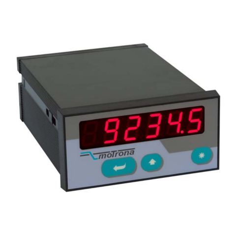
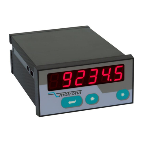
Motrona MS 640 User manual

Ms640_02b_oi_e.docx / Sep-22 Page 1 / 54
MS 640
Programmable Motion Monitor for Secure and
Redundant Control of Motion Sequences
•Suitable for monitoring of overspeed, underspeed, standstill, direction of rotation,
slip, shaft or gearbox fracture, impermissible motion etc.
•Six logical inputs for plausibility considerations and control of logical conditions
•Two programmable inputs for quadrature encoders
(each A, /A, B, /B for counting frequencies up to 500 kHz)
•Four safety relays with forced-guided contacts and four high-speed transistor
outputs, all with feedback and control of the actual output state
•Serial RS232 and RS485 interfaces for remote access to all functions and data
•High safety level on the machine site by redundant and logical control algorithms
•High functional safety of the monitor itself by internal test routines and diagnostics
Operating Instructions

Ms640_02b_oi_e.docx / Sep-22 Page 2 / 54
Safety Instructions
•This manual is an essential part of the unit and contains important hints about
function, correct handling and commissioning. Non-observance can result in
damage to the unit or the machine or even in injury to persons using the
equipment!
•The unit must only be installed, connected and activated by a qualified electrician
•It is a must to observe all general and also all country-specific and application-
specific safety standards
•When this unit is used with applications where failure or maloperation could cause
damage to a machine or hazard to the operating staff, it is indispensable to meet
effective precautions in order to avoid such consequences
•Regarding installation, wiring, environmental conditions, screening of cables and
earthing, you must follow the general standards of industrial automation industry
•- Errors and omissions excepted –
General instructions for cabling, screening and grounding can be found in the
SUPPORT section of our website http://www.motrona.com
Version:
Description:
MS64001a/mb/hk_05/2010
Preliminary version
MS64001b/pp_12/2011
Inserted new picture
MS64001c/mb/nw_02/2013
Adjustment of the ambient temperature
MS64002a/mb/nw_04/2013
Extension of Parameter F10.146 “Start Display”
Ms640_02b_oi/mbo_09/2022
Chapter10: Picture inserted, standards updated

Ms640_02b_oi_e.docx / Sep-22 Page 3 / 54
Table of Contents
1. Introduction and Application .................................................................................................................4
2. Electrical Connections...........................................................................................................................5
2.1. Connection Diagram .....................................................................................................................5
2.2. Terminal Assignments..................................................................................................................6
2.3. Power Supply................................................................................................................................7
2.4. Auxiliary Outputs for Encoder Supply ..........................................................................................7
2.5. Impulse Inputs for Incremental Encoders.....................................................................................8
2.6. Control Inputs 1 –4 ......................................................................................................................9
2.7. Logical Inputs Login1 - 6...............................................................................................................9
2.8. High Speed Transistor Outputs Out 1n - Out 4n (n = normal) and Out 1s - Out 4s (s = safe) ....9
2.9. Forced-Guided Safety Relays Rel.1s - Rel.4s.............................................................................10
2.10. Serial Interface ...........................................................................................................................11
3. Relevant Process Data and Setpoints..................................................................................................12
3.1. Available Actual Values .............................................................................................................12
3.2. Available Setpoints ....................................................................................................................13
3.3. Available Criteria for Combination of Switching Events ...........................................................13
3.4. Generation of an Output Signal .................................................................................................15
3.5. Indication of Switching Functions..............................................................................................16
3.6. Operation of the Status Signals.................................................................................................16
4. Setup of the Unit by PC .......................................................................................................................17
4.1. PC connection .............................................................................................................................17
4.2. The Main Screen ........................................................................................................................17
4.3. PC Screen for Configuration of Switching Functions.................................................................19
5. Keypad Operation................................................................................................................................21
5.1. Normal Operation .......................................................................................................................21
5.2. General Setup Procedure............................................................................................................21
5.3. Change of Parameter Values on the Numeric Level..................................................................23
5.4. Code Protection against Unauthorized Keypad Access.............................................................24
5.5. Return from the Programming Levels and Time-Out Function ..................................................24
5.6. Reset all Parameters to Factory Default Values........................................................................24
6. Menu Structure and Description of Parameters ..................................................................................25
6.1. Summary of the Menu................................................................................................................25
6.2. Description of the Parameters ...................................................................................................27
7. Important Hints for the User................................................................................................................38
7.1. Description of keypad commands and remote commands........................................................38
7.2. Hints for Scaling of the Unit.......................................................................................................40
7.3. Example for the Function of the Digital Filter............................................................................42
7.4. Internal Self-Testing Functions of the Monitor .........................................................................43
7.5. Manual Release of a Self-Testing Cycle....................................................................................44
7.6. Behavior in Case of Error, Error Messages................................................................................45
7.7. Display of Switching Functions and Principle of Operation of Parameter "Target Display" ...46
7.8. Temporary Interruption of the Display of Switching States......................................................47
7.9. Operation of the Watchdog Function.........................................................................................47
7.10. Behavior of the Monitor after Power up ....................................................................................47
8. Serial Access Codes............................................................................................................................48
9. Technical Specifications .....................................................................................................................53
10. Dimensions .........................................................................................................................................54

Ms640_02b_oi_e.docx / Sep-22 Page 4 / 54
1. Introduction and Application
The MS640 motion monitor has been designed for monitoring and control of admissible and
impermissible operating conditions on machinery systems. This unit is not just a speed monitor,
but provides comparison between peripheral motion, motor motion and actual operator
commands. The control functions include all actual values of two independent encoders
(speeds, directions of rotation, standstill, positions and differential positions between the two
encoders). The MS640 monitor is intended to generate alarms upon programmable coincidence
of measuring values and events by means of four relay outputs and four transistor outputs.
The example below shows a hoisting unit where a motor moves the load up and down, via
gearbox or other mechanical transmission.
UP
DOWN
Fastspeed
Break
Command MS 640
Motor
-------Gearbox-------
Encoder 1
Encoder 2
In a situation like shown the MS640 unit could e.g. provide the following alarms:
a) The operator command is "UP" but the motor or the load do not reach the scheduled
speed in time (overload or mechanical problem)
b) No move command is applied and the break is engaged, but still the motor or the load
are moving (break problem)
c) The commands are “Slow" and "Down” but the actual speed of the load exceeds the
permissible “Slow Speed” limit
d) the displacement of the load indicated by encoder 2 does not match up with the number
of pulses generated by encoder 1, with consideration of the gearbox ratio (slip problem)
Furthermore the MS640 can take over limit switch functions for the permissible upper and
lower positions of the load etc. All desired functions can be easily configured by PC, just by
clicking a few checkboxes in a “logical AND / OR” matrix on the screen.
MS 640 provides various internal safety functions and automatic self-test routines in order
to ensure a maximum of functional safety for the whole monitoring system (see 7.4 - 7.9).

Ms640_02b_oi_e.docx / Sep-22 Page 5 / 54
2. Electrical Connections
2.1. Connection Diagram
+5
-
A
/A
B
/B
+5
-
A
/A
B
/B
Encoder 1*)
Encoder 2*)
Input 1
Input 2
Input 3
Input 4
Control Inputs
RxD
TxD
GND
RS232
Com+
Out 1n
Out 2n
Out 3n
Out 4n
Fast transistor outputs
without control (n)
+24
+24
18
24
23
20
19
22
21
11
12
6
5
27
28
3
4
29
26
25
7
8
210
9
*) The example shows
TTL encoders using a
+5 V power supply
Login 4
7
Logical Inputs
Login 5
Login 6
Login 1
Login 2
Login 3
XA = 1 - 16
XB = 17 - 32
14
30
31
8
9
10
11
12
15 B (-)
A (+) RS485
Out 1s
Out 2s
Out 3s
Out 4s
1
17
1
2
3
4
5
6
7
8
9
10
11
12
Com+s
NO
C
NC
NO
C
NC
NO
C
NC
NO
C
NC
Rel 4s
Rel 3s
Rel 2s
Rel 1s
-
+Power supply
24 VDC or 24 VAC
1
2
3
4
5
(XD) (XC)
Fast transistor outputs,
safety-controlled (s)
Relay outputs, forced-guided
and safety-controlled (s)
17 18 19 20 21 23 24 25 26 27 28 29 30 31 32
1 2 3 4 5 6 7 8 9 10 11 12 13 14 15 16
Rel.1Rel.2Rel.3Rel.4
XA
XB
XC
XD

Ms640_02b_oi_e.docx / Sep-22 Page 6 / 54
2.2. Terminal Assignments
XA/XB
Name
Function
01
GND
Common Ground Potential (0V)
02
+5,2V out
Aux. output 5.2V/150 mA for encoder supply
03
+24V out
Aux. output 24V/120 mA for encoder supply
04
GND
Common Ground Potential (0V)
05
Encoder 2, /B
Encoder 2, channel /B (B inverted)
06
Encoder 2, /A
Encoder 2, channel /A (A inverted)
07
Encoder 1, /B
Encoder 1, channel /B (B inverted)
08
Encoder 1, /A
Encoder 1, channel /A (A inverted)
09
Out 4n
Digital output, transistor PNP 30 volts, 350 mA (no safety feedback)
10
Out 3n
Digital output, transistor PNP 30 volts, 350 mA (no safety feedback)
11
Input 4
Programmable control input
12
Input 3
Programmable control input
13
(PROG)
(for download of new firmware only, not for general use)
14
RxD
Serial RS232 interface, input (Receive Data)
15
RS485 B (-)
RS 485 serial interface
16
RS485 A (+)
RS 485 serial interface
17
+Vin
Power supply input, +17 –40 VDC or 24 VAC
18
+5,2V out
Aux. output 5,2V/150 mA for encoder supply
19
+24V out
Aux. output 24V/120 mA for encoder supply
20
GND
Common Ground Potential (0V)
21
Encoder 2, B
Encoder 2, channel B (non-inverted)
22
Encoder 2, A
Encoder 2, channel A (non-inverted)
23
Encoder 1, B
Encoder 1, channel B (non-inverted)
24
Encoder 1, A
Encoder 1, channel A (non-inverted)
25
Out 2n
Digital output, transistor PNP 30 volts, 350 mA (no safety feedback)
26
Out 1n
Digital output, transistor PNP 30 volts, 350 mA (no safety feedback)
27
Input 2
Programmable control input
28
Input 1
Programmable control input
29
Com+
Common positive input for transistor outputs Out 1n - Out 4n
30
TxD
Serial RS232 interface, output (Transmit Data)
31
GND
Common Ground Potential (0V)
32
GND
Common Ground Potential (0V) for DC or AC power supply
*) 120 mA and 150 mA are per encoder, i.e. total maximum currents are 240 mA and 300 mA

Ms640_02b_oi_e.docx / Sep-22 Page 7 / 54
XC
Name
Function
01
Rel4-NO
Relais 4, Schließer
02
Rel4---C
Relais 4, gemeinsamer Kontakt
03
Rel4-NC
Relais 4, Öffner
04
Rel3-NO
Relais 4, Schließer
05
Rel3---C
Relais 4, gemeinsamer Kontakt
06
Rel3-NC
Relais 4, Öffner
07
Rel2-NO
Relais 4, Schließer
08
Rel2---C
Relais 4, gemeinsamer Kontakt
09
Rel2-NC
Relais 4, Öffner
10
Rel1-NO
Relais 4, Schließer
11
Rel1---C
Relais 4, gemeinsamer Kontakt
12
Rel1-NC
Relais 4, Öffner
XD
Name
Function
01
Com +s
Eingang für die Schaltspannung der Ausgänge Out 1s - Out 4s
02
Out 1s
Digitalausgang, Transistor PNP 30 V, 350 mA (gesichert)
03
Out 2s
Digitalausgang, Transistor PNP 30 V, 350 mA (gesichert)
04
Out 3s
Digitalausgang, Transistor PNP 30 V, 350 mA (gesichert)
05
Out 4s
Digitalausgang, Transistor PNP 30 V, 350 mA (gesichert)
06
GND
Gemeinsames Potenzial GND
07
Login 1
Eingang für Logikverknüpfungen Login1
08
Login 2
Eingang für Logikverknüpfungen Login2
09
Login 3
Eingang für Logikverknüpfungen Login3
10
Login 4
Eingang für Logikverknüpfungen Login4
11
Login 5
Eingang für Logikverknüpfungen Login5
12
Login 6
Eingang für Logikverknüpfungen Login6
2.3. Power Supply
The MS640 monitor accepts both, a 17 –40 volts DC power or a 24 volts AC power for supply
via terminals XA-1 and XB-17. The current consumption depends on the level of the input
voltage and some internal conditions; therefore it can vary in a range from 100 –200 mA (aux.
currents taken from the unit for encoder supply not included).
2.4. Auxiliary Outputs for Encoder Supply
Terminals 2 and 18 provide an auxiliary output with approx. +5.2 volts DC (300 mA totally).
Terminals 3 and 19 provide an auxiliary output with approx. +24 volts DC (240 mA totally)

Ms640_02b_oi_e.docx / Sep-22 Page 8 / 54
2.5. Impulse Inputs for Incremental Encoders
All input characteristics of the impulse inputs can be set by the parameter menu, for each of
the encoders separately.
Due to the high safety demands made on this unit it is mandatory to use quadrature encoders
only (A, B or A, /A, B, /B, 90°)
The following levels and impulse standards can be used:
•Symmetric inputs (differential) according to RS422 standard
(A, /A; B, /B, minimum differential voltage 1 V)
•Differential TTL inputs with 3.0 to 5 volts level
(A, /A; B, /B, minimum differential voltage 1 V)
•Differential HTL inputs with 10 –30 volts level
(A, /A; B, /B, minimum differential voltage 1 V)
•Single-ended HTL inputs with 10 - 30 volts level
(channels A and B only)
•Single-ended TTL inputs with 3.0 to 5 volts level *)
(channels A and B only)
*) For exceptional application only, since sensitive to EMC interference.
Requires special settings of the threshold parameters, see “Special parameters F10”

Ms640_02b_oi_e.docx / Sep-22 Page 9 / 54
2.6. Control Inputs 1 –4
These inputs can be configured for remote functions like Reset, disable of the keyboard or
display selection purpose etc. All control inputs require HTL level (12 ... 30 volts). The
characteristics can be individually set to either NPN (switch to -) or PNP (switch to +). For
applications where edge-triggered action is needed, the menu allows to set the active edge
(rising or falling). The control inputs will also accept signals according to Namur standard.
For reliable operation of the control inputs, minimum impulse duration of 50 µsec.
must be ensured. Please verify that this minimum duration will be kept even at
maximum speed of the machine
2.7. Logical Inputs Login1 - 6
The logical inputs are available for process control. These inputs receive logical information
from the process (e.g. actual operator commands or limit switch information). The monitor can
compare this information to the feedback information of the encoders and verify if the operator
command is executed correctly or not.
Each of the 6 inputs provides programmable switch-on and switch-off delays, in order to allow
acceptable response delays to electrical and mechanic parts before comparing the actual state
and the scheduled state.
All logical inputs operate at HTL level (12 ... 30 volts) with PNP (switch to +) characteristics.
2.8. High Speed Transistor Outputs
Out 1n - Out 4n (n = normal) and Out 1s - Out 4s (s = safe)
The MS640 monitor provides 2 x 4 fast-switching transistor outputs, all short-circuit-proof, with
a switching capability 5 - 30 volts / 350 mA each (response time < 1 msec.)
The functions of outputs Out 1n - Out 4n are in parallel to the functions of outputs Out 1s to
Out 4s, so that only 4 different switching functions can be assigned to the 8 outputs.
Out 1n - Out 4n operate without internal feedback and without control of their switching state.
Out 1s to Out 4s provide internal feedback with continuous control of the correct output state
as well as monitoring of overload, short-circuit and idle state (cable break)
When one of the outputs Out 1s - Out 4s is not used or remains unconnected, it must be
deactivated by means of parameter "Output Error Config.", otherwise a permanent "cable
break" alarm will be indicated

Ms640_02b_oi_e.docx / Sep-22 Page 10 / 54
2.9. Forced-Guided Safety Relays Rel.1s - Rel.4s
The four relays provide two dry change-over contacts each with forced-guided mechanical
construction. The switching capability is 250 VAC / 1 A / 250 VA or 100 VDC / 1 A / 100 W and
the response time of the relays is in a range of 5 to 10 msec.
In each case one set of the forced-guided contact pair is available for the user whereas the
other contact set is used for internal feedback control. The processor monitors at any time, with
consideration of the operate times of the relays, if the contact position coincides with the
internal excitation of the coil, and discrepancies will cause an immediate alarm.
The following chapters describe how to assign control and switching functions to the relays
and the outputs. For programming of the switching conditions a PC with operator software
OS32 is used. The multitude of possible combinations between input information (logical
states), encoder feedback (actual states) and programmable switching levels offers
outstanding options for safety-related motion monitoring of all kinds of machinery.
It is possible to add any of the following characteristics to the resulting switching functions:
•Positive or negative response (active switching state ON or OFF)
•Switch-on and switch-off delays: the switching function will become active after
programmable on-off times only to allow the mechanics to respond
•Timed or static operation: when the event occurs, the output can provide either
dynamic (timed) operation or static operation
•Programmable catch functions with or without power-down storage: All switching
functions can be set to "Lock" so that the corresponding switching function remains
active until operator reset

Ms640_02b_oi_e.docx / Sep-22 Page 11 / 54
2.10. Serial Interface
The serial RS232 interface can be used for the following purposes:
•Set-up of the unit by PC by means of the OS32 PC software
•Change of parameters during operation
•Readout of actual speeds or positions or other counter values by PLC or PC
•Running of functional checks of the monitor, under remote control of a superior system
The figure below shows how to connect the MS640 monitor to a PC or a PLC
2
3
5
RxD RxD
TxDTxD GND
Screen
PC
MS 640 14
(Sub-D-9)
30
31
RS 232
PLC
MS 640 16
15
RS 485
A
B
A
B
Both serial interfaces can be connected at the same time.
However only the one or the other must communicate at a time.
It is not possible to communicate simultaneously with both interfaces

Ms640_02b_oi_e.docx / Sep-22 Page 12 / 54
3. Relevant Process Data and Setpoints
3.1. Available Actual Values
Depending on the connected encoders and sensors, the monitor continuously measures and
updates the actual values shown in the list below. This means that every of these actual values
is available at any time for evaluation and can be combined with other functions to switch one
of the outputs ON or OFF.
Value/State
Description
Requirement
Standstill 1
Digital information (yes/no) for zero motion
of encoder 1 *)
Incremental signal on
Encoder 1 input
Motion signal 1
Digital information (yes/no) for active
motion of encoder 1
Incremental signal on
Encoder 1 input
Speed 1
Actual speed of encoder 1 according to
customer scaling
Incremental signal on
Encoder 1 input
Position 1
Actual position count of encoder 1
according to customer scaling **)
Quadrature encoder for
encoder input 1
Direction 1
Direction of motion (forward or reverse)
of encoder 1
Quadrature encoder for
encoder input 1
Standstill 2
Digital information (yes/no) for zero motion
of encoder 2 *)
Incremental signal on
Encoder 2 input
Motion signal 2
Digital information (yes/no) for active
motion of encoder 2
Incremental signal on
Encoder 2 input
Speed 2
Actual speed of encoder 2 according to
customer scaling
Incremental signal on
Encoder 2 input
Position 2
Actual position count of encoder 2
according to customer scaling **)
Quadrature encoder for
encoder input 2
Direction 2
Direction of motion (forward or reverse)
of encoder 2
Quadrature encoder for
encoder input 2
Difference
Pos 1 - Pos 2
Differential position count between
encoder 1 and encoder 2, according to
customer scaling **)
Quadrature encoders for both,
encoder 1 and encoder 2
*) Standstill can be defined by parameter setting
**) “Zero position” and “Zero difference” can be defined by individual RESET

Ms640_02b_oi_e.docx / Sep-22 Page 13 / 54
3.2. Available Setpoints
For configuration of the switching conditions of the relays, the following setpoints are
available. Every setting is individual for each of the four switching functions.
In total there are 4 x 7 = 28 programmable setpoints available.
Settings can be omitted if the corresponding setpoints have not been assigned to a switching
function.
Setpoint
Description
Set Speed 1.1
Set Speed 1 for Encoder 1
Set Speed 1.2
Set Speed 2 for Encoder 1
Set Speed 2.1
Set Speed 1 for Encoder 2
Set Speed 2.2
Set Speed 2 for Encoder 2
Setpoint Counter 1
Position setpoint for Encoder 1
Setpoint Counter 2
Position setpoint for Encoder 2
Differential Setpoint
Differential position setpoint (encoder 1 –encoder 2)
3.3. Available Criteria for Combination of Switching Events
Every of the four available output functions provides 4 programmable switching events which
can again be combined from several switching conditions (logical AND).
As soon as one or several of the four events become true, the corresponding function will be
activated or deactivated (logical OR) and as a result one of the output according to assignment
will switch on or off (see 3.4 and 4.3).
3.3.1. Logical switching conditions
Condition
Description of the Switching Condition
Login1 or /Login1
All functions allow gating with one or several of the 6 logical Inputs.
-Login X means that a “HIGH” signal is needed to make the
condition true
-/Login X means that a “LOW” signal is needed to make the
condition true
Login2 or /Login2
Login3 or /Login3
Login4 or /Login4
Login5 or /Login5
Login6 or /Login6

Ms640_02b_oi_e.docx / Sep-22 Page 14 / 54
3.3.2. Speed related switching conditions
Condition
Description of the Switching Condition
[v1] ≤Set Speed1.1
The absolute value of the actual encoder1 speed is lower or equal to the set
speed 1.1
[v1] ≥Set Speed1.1
The absolute value of the actual encoder1 speed is higher or equal to the set
speed 1.1
[v1] ≥Set Speed1.2
The absolute value of the actual encoder1 speed is higher or equal to the set
speed 1.2
[v1] = 0
Speed of encoder1 = zero (standstill according to standstill definition)
[v1] ≠0
Speed of encoder1 ≠zero (encoder1 is in motion)
[v2] ≤Set Speed2.1
The absolute value of the actual encoder2 speed is lower or equal to the set
speed 2.1
[v2] ≥Set Speed2.1
The absolute value of the actual encoder2 speed is higher or equal to the set
speed 2.1
[v2] ≥Set Speed2.2
The absolute value of the actual encoder2 speed is higher or equal to the set
speed 2.2
[v2] = 0
Speed of encoder2 = zero (standstill according to standstill definition)
[v2] ≠ 0
Speed of encoder2 ≠zero (encoder2 is in motion)
3.3.3. Position related switching conditions
Condition
Description of the Switching Condition
[c1] ≥Setpoint Counter1
The absolute value of the actual encoder1 counter is higher or equal to
“Position Setpoint 1” of the corresponding function
[c1] ≤Setpoint Counter1
The absolute value of the actual encoder1 counter is lower or equal to
“Position Setpoint 1” of the corresponding function
[c2] ≥Setpoint Counter2
The absolute value of the actual encoder2 counter is higher or equal to
“Position Setpoint 2” of the corresponding function
[c2] ≤Setpoint Counter2
The absolute value of the actual encoder2 counter is lower or equal to
“Position Setpoint 2” of the corresponding function
3.3.4. Direction related switching conditions
Condition
Description of the Switching Condition
c1 = + + +
Counter 1 counts upwards, Direction1 = Forward
c1 = - - -
Counter 1 counts downwards, Direction1 = Reverse
c2 = + + +
Counter 2 counts upwards, Direction2 = Forward
c2 = - - -
Counter 2 counts downwards, Direction2 = Reverse
3.3.5. Differential switching conditions
Event
Description of the Switching Condition
[c1 –c2] ≥Differential
Setpoint
The absolute value of the differential position between encoder1 and
encoder2 is higher or equal to the differential position setpoint of the
corresponding function
[c1 –c2] ≤Differential
Setpoint
The absolute value of the differential position between encoder1 and
encoder2 is higher or equal to the differential position setpoint

Ms640_02b_oi_e.docx / Sep-22 Page 15 / 54
3.4. Generation of an Output Signal
As a first step we have to arrange the desired Switching Events, which can be composed from
any combination of the switching conditions as described above. Every event consists of one or
several conditions according to the selection of check boxes on the PC screen (see 4.3). Several
events (1 - 4) are combined to a Switching Function. The parameters named "Target Function"
allow the assignment of an output to each function, where the switching signal finally appears.
Also the internal status bits become accessible via output if a corresponding assignment has
been made. The assignment of outputs uses an 8-bit binary code as shown below.
Event 1.1 or
Function 1
Function 2
Function 3
Function 4
Status 1
Status 2
Status 3
Status 4
Output 4
Output 3
Output 2
Output 1
Relay 4
Relay 3
Relay 2
Relay 1
Target Function 1
Target Function 2
Target Function 3
Target Function 4
Target Status 1
Target Status 2
Target Status 3
Target Status 4
(Ready)
Definition of the
Switching Functions Output Assignment Target
(128)
(064)
(032)
(016)
(008)
(004)
(002)
(001)
Assignment Code
(binary)
(Keypad Operation)
(customer specific)
or
or
Event 1.2
Event 1.3
Event 1.4
Event 2.1 or
or
or
Event 2.2
Event 2.3
Event 2.4
Event 3.1 or
or
or
Event 3.2
Event 3.3
Event 3.4
Event 4.1 or
or
or
Event 4.2
Event 4.3
Event 4.4
(Collective Error Signal)

Ms640_02b_oi_e.docx / Sep-22 Page 16 / 54
3.5. Indication of Switching Functions
With some applications it can be useful to just present actual events and switching functions o
the display without affecting an alarm output. Similarly a visual display of actually active
events may be desirable in addition to an alarm output. Therefore, quite according to the
parameters "Target Function", the parameters "Target Display" provide assignment of a display
function to the switching functions, which can either be used alone or together with an output
action. All corresponding details are explained in chapter 7.7.
3.6. Operation of the Status Signals
3.6.1. Status 4 (Ready)
This status signal is active (log. 1) to indicate that the hardware of the unit is ready for proper
operation and no fault could be detected inside the monitor itself (see chapter 7.4).
3.6.2. Status 3 (Keypad Operation)
During any access to the parameters via the keypad of the unit itself, all external monitoring
functions are temporary disabled. A logical "1" state of this signal indicates that the control
functions are disabled due to keypad access to the unit. At the same time also the Ready signal
is switched off. *)
3.6.3. Status 2 (Collective Error Signal)
This status signal is active (log. 1) to indicate that an error or an abnormality has been detected
during the automatic self-testing routines running continuously in the background, At the same
time the Ready signal will switch off and an error code will be generated and indicated on the
LED display. A fully itemized error code is also accessible via serial link (see 7.6 for details)
3.6.4. Status 1 (customer-specific)
This signal is reserved for customer-specific use according to agreement.
With all standard units the Status 1 signal is permanently switched off.
*) It is at any time possible to read out or to change parameters and settings by communication via
serial interface, while all control remains fully active and no functions will be disabled

Ms640_02b_oi_e.docx / Sep-22 Page 17 / 54
4. Setup of the Unit by PC
4.1. PC connection
For initial setup of the MS640 Motion Monitor a PC with the motrona OS32 operator software
is required (Software version OS32_02a or higher). This software is included on CD and is also
available for free download from our homepage www.motrona.com.
The software allows to set all basic parameters and to assign the desired switching functions
to the outputs. During later operation, the four programming keys on the front side of the unit
can be used to change settings like Setpoints or scaling parameters (see chapter 5.).
Connect your PC to the monitor as shown under 2.7 and start the OS32 software.
The adjoining screen will appear.
If your text and color fields remain empty and the headline says „OFFLINE“, you must verify
your serial settings. To do this, please select “Comms“ from the menu bar.
•Ex factory, all motrona units use the following serial standard settings:
Unit No. 11, Baud rate 9600, 1 start/ 7 data/ parity even/ 1 stop bit
•If the serial settings of your unit should be unknown, you can run the “SCAN“
function from the „TOOLS“ menu to find out.
4.2. The Main Screen
The edit window for all unit parameters can be found on the left side of the screen.
To enter your parameters, please click to the corresponding line, enter a new value and save
the new value by pressing ENTER on your PC keyboard.
You can also just change all digits according to need, then finally click to the Softkeys
“Transmit All” followed by “Store EEProm” to save all your settings.
The INPUTS field provides Softkeys to switch the control commands on or off.
Display boxes in the RS column indicate when the corresponding command is set to ON by PC.
Display boxes in the PI/O column indicate that commands assigned to the hardware inputs
(input1 to input4) are switched ON by external signal.
Command "Select Variables" (marked by red pointer in the screenshot) is reserved for factory
use only. For normal operation this command must be inactive (off) at any time to allow proper
use of the PC software.
The OUTPUT field informs about the actual switching state of the four outputs Out1 - Out4
and the four relays Rel1 - Rel4.

Ms640_02b_oi_e.docx / Sep-22 Page 18 / 54

Ms640_02b_oi_e.docx / Sep-22 Page 19 / 54
4.3. PC Screen for Configuration of Switching Functions
To open the Assignment screen, select “Config. MM/MS” from the Tools Menu.
You can assign any combination of switching events and functions to the outputs or relays by
clicking to the corresponding boxes of conditions as described before.
In the “Options” column you find a list of all actual motion conditions as described under 3.3
Checkboxes allow activation or deactivation of the corresponding event as one of the desired
switching conditions (click the corresponding box to switch it on or off).
•All checkboxes of a vertical column (representing conditions) operate "Logical AND"
and form a "Switching Event."
•Always four adjoining columns (events) operate "Logical OR" and form a Switching
Function. If one or several of the events become true, the switching function will
become active.
•You are free to activate any number and combination of checkboxes. Setting
checkboxes with conflictive conditions should however be avoided. *)
•The destination output for each switching function can be set by means of the
parameter "Target Function".
It is possible to assign different switching functions to the same output
(e.g. Function1 => Relay1 and Function2 => Relay1)
Likewise it is possible to assign several outputs to the same switching function (e.g.
Function1 => Relay1 and Relay2)
*) Where e.g. you would set both checkboxes “v=0” and “v≠0“ at the same time, this
would result in a conflict where the corresponding output would never switch off.
The adjoining screenshot shows the following four events to activate Switching Function 1:
Login1 = LOW and Login2 = High and Encoder1 = Standstill
(event 1.1)
or
Login2 = High and Speed1 ≥Set Speed1.1 and Forward Motion of Encoder1
(event 1.2)
or
Login3 = High
(event 1.3)
or
Reverse motion of Encoder 2
(event 1.4)
It is easy to understand how many possibilities of monitoring speeds and events result from
this simple method of programming.

Ms640_02b_oi_e.docx / Sep-22 Page 20 / 54
Table of contents
Other Motrona Measuring Instrument manuals

Motrona
Motrona AX 342 User manual

Motrona
Motrona DX350 User manual

Motrona
Motrona AX320 User manual

Motrona
Motrona IX348 User manual

Motrona
Motrona AX020 User manual

Motrona
Motrona touchMATRIX PN350 User manual

Motrona
Motrona touchMATRIX MX350 User manual

Motrona
Motrona SD Series User manual

Motrona
Motrona TouchMATRIX DM350 User manual

Motrona
Motrona touchMATRIX DP350 User manual