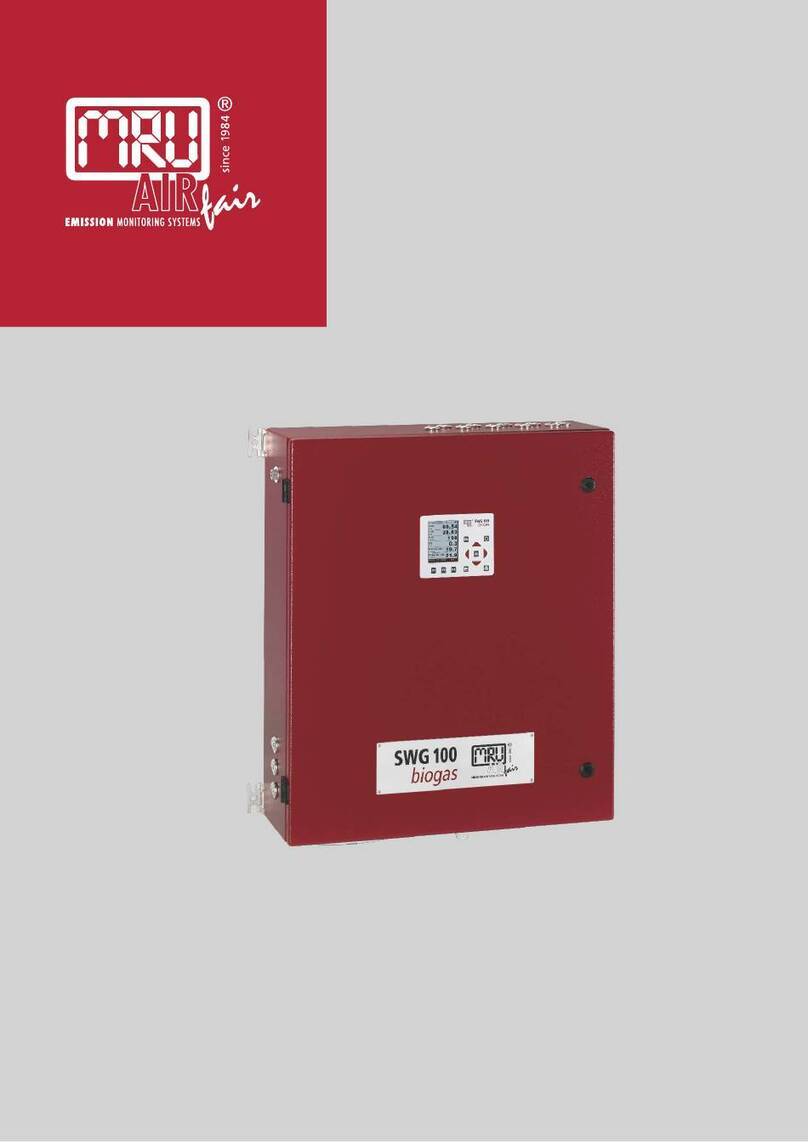
mru SWG100 BIOEX User manual

SWG100BIO Ex. User Manual
MRU GmbH, D-74172 Neckarsulm
1 / 108

SWG100 BIOGAS User Manual
MRU GmbH, D-74172 Neckarsulm
2 / 108

SWG100BIO Ex. User Manual
MRU GmbH, D-74172 Neckarsulm
3 / 108
Content
1. General Information.......................................................................................................... 6
1.1. Weather and environmental conditions...................................................................... 6
1.2. Installation instructions............................................................................................... 6
1.3. General important instructions for the plant operator.................................................6
2.1. Important information about the user’s operation manual..........................................7
11.1. General warning......................................................................................................... 7
11.2. Safety Information...................................................................................................... 7
11.3. Packing...................................................................................................................... 9
11.4. Return of hazardous waste........................................................................................ 9
11.5. Return of analyzer...................................................................................................... 9
11.6. MRU guarantee conditions....................................................................................... 10
12. Analyzer Description...................................................................................................... 11
12.1. Intended use............................................................................................................ 11
12.2. Principle of operation............................................................................................... 12
12.3. Marking and range of application.............................................................................13
12.4. Possible applications and analyzer options .............................................................13
12.5. Features................................................................................................................... 13
13. Overview of the SWG-100BIO Ex................................................................................... 14
13.1. Scope of supply and delivery...................................................................................14
13.2. Material required for the installation (not scope of supply).......................................14
13.3. Dimensions and views of the analyser..................................................................... 15
13.4. Position of the gas in and outlets.............................................................................16
13.5. Operating unit: Display and keypad.........................................................................17
14.1. Measurement menu................................................................................................. 19
15. Explosion protection systems of SWG100BIO-EX....................................................... 20
15.1. Electrical components.............................................................................................. 20
15.2. IP 65 cabinet............................................................................................................ 20
15.3. CH4measurement of inside cabinet......................................................................... 21
15.4. Remote Power Supply Box...................................................................................... 24
16. Sample Gas measurement............................................................................................. 27
16.1. Cycle configuration..................................................................................................27
16.2. H2Slow sensor protection (optional)........................................................................32
17. Analyzer mounting and installation.............................................................................. 34
17.1. Content of your order............................................................................................... 34
17.2. Installation rules to guarantee explosionprotection................................................. 34
17.3. Prerequisites for installation.....................................................................................34
17.4. Steps for the mechanical mounting and installation.................................................35
17.5. Mounting the analyser on a wall or steel rack..........................................................36
17.6. Correct tubing of the SWG100BIO-Ex.....................................................................37
18.1. Flow restrictor orifice (#65114).................................................................................38
18.2. Installation of the power supply................................................................................ 40
18.3. Installation of the externalswitch-off circuit..............................................................41
18.4. Connection of the I/O module.................................................................................. 43
19. Power up and commissioning the analyser................................................................. 45
19.1. Power up the analyser.............................................................................................46
19.2. Check country and language................................................................................... 47
19.3. Check date and time of the instrument....................................................................47
SWG100 BIOGAS User Manual
MRU GmbH, D-74172 Neckarsulm
4 / 108
19.4. Configure sampling points ....................................................................................... 47
19.5. Configuration of the alarm relays............................................................................. 48
19.6. Configuration of the Modbus.................................................................................... 50
19.7. Configuration of the externalcontrol (Option: IO module)........................................ 52
19.8. Configuration of the analog outputs at the I/O module............................................. 56
19.9. Configure alarm output of I/O module...................................................................... 57
19.10. Configure the AUX-input on software-side:......................................................... 59
20. Operating the analyser................................................................................................... 60
20.1. Administrator PIN code............................................................................................ 60
20.2. Power-On of analyser.............................................................................................. 60
20.3. Self-Test .................................................................................................................. 60
20.4. Main menu measurement........................................................................................ 61
20.5. Data Storage............................................................................................................ 63
20.6. Power-Down of analyzer.......................................................................................... 64
20.7. Backup/restore all individual user-settings............................................................... 65
20.8. Default configuration................................................................................................ 65
20.9. Update the firmware................................................................................................. 67
21. Service and maintenance............................................................................................... 70
21.1. Preparing and information about the maintenance.................................................. 70
21.2. Regular maintenance works by the operator........................................................... 70
21.3. Position and overview of the service-parts............................................................... 71
21.4. Cleaning the surface of SWG100BIO-Ex................................................................. 77
21.5. Maintenance of the switch-off relay (K2) and the solenoid valve for CH4 supervision
77
22. Exchange of electrochemical sensors.......................................................................... 79
22.1. Analyzer calibration.................................................................................................. 86
23.1. Troubleshooting....................................................................................................... 90
24. Technical specification.................................................................................................. 91
25. Declaration of conformity.............................................................................................. 95
26. APPENDIX....................................................................................................................... 99
27. General information........................................................................................................ 99
27.1. Special informationen about the Modbus Slave function......................................... 99
27.2. Special informationen about the Profibus Slave function....................................... 100
28. Defined registers to be read by the master................................................................ 101
28.1. Analyser Status (address 0 and some mirror addresses)...................................... 104
28.2. Analyser System Alarm (address 2 and some mirror addresses).......................... 105
28.3. Spare parts list....................................................................................................... 106

SWG100BIO Ex. User Manual
MRU GmbH, D-74172 Neckarsulm
5 / 108
Inspect Shipment for Damage
Carefully inspect the entire shipment for damage in the presence of the shipper’s agent,
removing packaging material if necessary. Note any damage to packaging and/or goods on
Packing List and have it signed by the shipper’s agent prior to accepting the shipment. Submit
damage claim to MRU immediately.
NOTE: Damage claims not received by MRU within 3 days of receipt of shipment will not be
accepted.
The products described in this manual are subject to continuous development and improvement
and it is therefore acknowledged that this manual may contain errors or omissions. MRU
encouragescustomer feedback and welcomes any comments or suggestions relating tothe
product or documentation.
Please forward all comments or suggestions to the Customer Feedback Department at the
following address:
MRU GmbH
Fuchshalde 8 + 12
74172 Neckarsulm / Obereisesheim
GERMANY
Fon (+49) 71 32 99 62 0 (Reception)
Fon (+49) 71 32 99 62 61 (Service)
Fax (+49) 71 32 99 62 20
Email: info@mru.de
Homepage: www.mru.eu
This manual is intended solelyas a guide to the use of the product.
MRU shall not be liable for any loss or damage whatsoever arising from content errors or
misinterpretation of information’s from this manual or any mis-use resulting from the use of this
manual.
FOR MORE INFORMATIONS ABOUT COMPANY MRU PLEASE VISIT OUR WEBSITE
www.mru.eu

SWG100 BIOGAS User Manual
MRU GmbH, D-74172 Neckarsulm
6 / 108
1. General Information
1.1.Weather and environmental conditions
The SWG100BIOGAS analyser is designed for operating ambient temperatures of +5°C to
+45°C (without cabinet heater) resp. -20°C to +45°C (with cabinet heater).
The SWG100BIO-Ex. is for designed for use in hazardous Zone 2, see the conformity marking
in the corresponding section.
In case of outdoormounting it is important that the analyser is protected against rain andsun.
For extreme environmental conditions like high humidity, salty sea air, etc. further protective
measures are necessary. These should be clarified with themanufacturer (MRU).
Any additional protective measures for outdoor mounting have to be provided by the plant
operator. The manufacturer (MRU) is supporting the plant operator in choosing appropriate
protective measures.
1.2.Installation instructions
Installation instructions, which are described in chapter 17 of the operation manual, have to be
strictly carried out.
WARNING
Please check correct installation before powering up the analyzer!
Please operate the analyzer only in upright position!
1.3.General important instructions for the plant operator
To guarantee continuous operation of the SWG100 BIOGAS analyser, the functions, processes
and operation of the analyser have to be monitored regularly by the plant operator – especially
in case of any initial installation. Thus, it will be possible to take suitable measures to improve
the availability and life time of the analyser.
As the plant operator gains more experience concerning the maintenance requirements of the
analyser, the monitoring frequency may be reduced to more extended periods of time.
It is important that the filter-units, listed in chapter 10 of the operation manual, are checked
regularly and, if necessary, service parts are changed.
2.
ATTENTION
In case of not intended use the guarantee will void. Regular controls,
inspections and the exchange from polluted and exhausted filters by
the operator are also an important part of the determination “not
determined use”. See chapter 9 regular maintenance work.

SWG100BIO Ex. User Manual
MRU GmbH, D-74172 Neckarsulm
7 / 108
2.1.Important information about the user’s operation manual
The users/operation manual is an important part of this delivery. It will explain how to use this
analyzer properly and sets forth safety and environmentally friendly procedures.
It is the responsibility of all users to read and familiarize themselves with this manual, paying
particular attention to the safety instructions.
The most importantsafety details are clearly marked with anattention sign.
Safety declarations
In this document the safety hints will be declared as follow:
DANGER
Identifies an immediate, impending hazard that, if ignored, will
result in severe bodily injuries or death.
3
4
WARNING
Identifies an immediate, impending hazard that, if ignored, may
result in severe bodily injuries, material damage or death.
5
6
CAUTION
Identifies a possibly dangerous situation that, if ignored, may result
in minor injuries.
7
9.
ATTENTION
Identifies a possibly harmful situation that, if ignored, may result in
damages to the device or its surroundings.
10
11.
NOTE
Identifies user tips and other especially important information.
11.1. General warning
DANGER
Any maintenance action must be done only, when the atmosphere is
verified to be not explosive.
11.2. Safety Information
The following safety procedures must be followed at all times. They are significant and essential
part of this manual. Failure to follow safety procedures can result in the loss of your warranty
claims.
Biogas or other similar gases (landfill gas, bio-methane, coal seam gas etc) is containing
flammable gas component CH4 and toxic gas component as well (H2S and CO2).
Analyzers is continuously sampling a certain volume (approx 50l/h) of the sample gas, and is
venting it to ambient air.
For this reason, there are two aspects which must be considered:
1) toxicity danger of sample gas

SWG100 BIOGAS User Manual
MRU GmbH, D-74172 Neckarsulm
8 / 108
2) flammable (explosion) danger of sample gas
1) Inhaling toxic gases is harmful to healthand can even cause death insome cases.
• It is the responsibility of analyzer user to ensure that person is skilled and trained
in safety aspects of gases being analyzed and procedures to follow while using this
instrument.
• Local regulations for possible exposition to toxic gases have to be known and obeyed
by the user of the analyzer
• Using a personal gas detector inside the biogas plant is highly recommended since
H2S in higher (very dangerous) concentration cannot be detected by human nose.
Only small concentrations around few ppm can be detected by human nose
• CO2 gas is heavier than air and therefore operator shall avoid working at underground
or confined spaces. Beside of that CO2 is also odorless!
• It is not allowed using the biogas analyzer in confined space or rooms
without forced ventilation.
• Sample gas exiting the analyzer will flow in the ambient air and only outdoor use
or forced ventilation rooms are suitable forusing the biogas analyzer
2) Regarding flammable gases (e.g. CH4 methane) and hazardous area of operating the
instruments, user must also be able to recognize the area classification and be aware of using
the instrument there. This area classification is country specific, please observe and notice it.
• Stationary analyzers are allowed to be mounted in hazardous area zone 2 only if they
have the certificate of compliance. These instruments shall never be located in
confined places or rooms without forced ventilation.
Only trained personnel should carry out installation of stationary instrument and/or
maintenance, service and repair. Opening the stationary analyzer cabinet can expose
personnel toinjuries and shocks from mains voltage!

SWG100BIO Ex. User Manual
MRU GmbH, D-74172 Neckarsulm
9 / 108
Safety regulations
The analyzer may only be used as indicated in this manual. Our analyzers are checked
according to the following regulations:
VDE 0411 (EN61010) and DIN VDE0701 before they leavethe MRU GmbHfactory.
MRU technical products are designed and manufactured according to DIN 31000/ VDE 1000
and UVV = VBG 4 of the professional guilds for fine mechanics andelectrical engineering.
MRU GmbH assures that the analyzer complies to the essential requirements of the legal
regulations of the member states of the electro-magnetic compatibility (89/336/EWG) and to the
low-voltage regulations (3/23/EWG).
Specific safety regulations
No part of the analyzer, or any other metal parts & accessories shall be used as electric
conductors.
The analyzer shall not be used in or under water.
The analyzer shall not be placed near ordirectly exposed to open fireor heat.
The analyzer shall avoid dropping.
CAUTION
Moisture or condensate, being pumped out of the condensate outlet
port can be slightly acidic.
In case of skin contact IMMEDIATELY: clean affected parts of the body.
Avoid getting liquid in eyes.
Please carefully clean all parts that come into contact with the
condensate.
11.3. Packing
Packing regulation of 12.07.1991
If your local waste facility does not accept MRU packing materialsfor disposal, you may return it
to MRU or our local sales representative. Packing materials returned to MRU must be returned
prepaid.
11.4. Return of hazardous waste
Waste Disposal/Returns/Warranty -
MRU GmbH is required to accept the return of hazardous waste such as electro-chemical
sensors that cannot be disposed of locally. Hazardous waste must be returned to MRU prepaid.
11.5. Return of analyzer
MRU GmbH is required to accept the return, for proper disposal, of all analyzers delivered after
13th of August 2005. Analyzers must be returned to MRU prepaid.

SWG100 BIOGAS User Manual
MRU GmbH, D-74172 Neckarsulm
10 / 108
11.6. MRU guarantee conditions
MRU granted ofthe analyzerSWG100 BIOGASa guarantee of 12month.
1. 6 month on MRU spare parts.
2. The term of the guaranteeconditionsstarts as of the invoice date.
3. Excluded from the guarantee conditions are damages, which occurred by:
•Improper use.
•Improper application.
•Improper mounting.
•Deliberate or negligent destructions.
•External influence for example fall, hits, solvents, acids, gases, by normal wear or
transport damages. This applies also for defects, which are caused from high pollution
and/or moisture (condensate) in the gas routeor on the sensors.
4. As well excludedfrom the guarantee conditions are typical consumable- and spare parts.
5. The guarantee condition denatured immediately, if no original consumable parts are installed.
The guarantee is only fororiginal MRU consumable partsand sensors.
6. With the replacement of the type plate or the serial- number of the devices all guarantee
conditions will be invalid.
7. The service of a guarantee conditions will not enlarge the guarantee time. Demands because
of consequential damages are excluded.
8. The transportcosts for round trip takes the consignor or the warrantee.
9. MRU reserves the right, to determine individual conditions or exceptions. These will be
separated informed.

SWG100BIO Ex. User Manual
MRU GmbH, D-74172 Neckarsulm
11 / 108
12. Analyzer Description
12.1. Intended use
The instrument is intended for analyzing the composition of biogases / biomethane / landfill
gases and determine the concentration of several components like CH4, CO2, O2 and H2S.
The instrument may optionally be equipped to monitor several sites in time sharing technique
(cyclical one by one sampling).
In particular, the instrument is not foreseen toserve as a gasdetector or as a safety device.
In case of not intended use the guarantee will void. Regular controls, inspections and the
exchange from polluted and exhausted filters by the operator are also an important part of the
determinations “not determined use”- see chapter 9 regular maintenance work.
The SWG-100BIO Ex. is an extractive measuring system. It has maximal 4 sample gas inlets, to
measure the gas concentration from 4 different sample points, one by one. It has an internal
gas pump to suck the sample gas from the sampling points.After the measurement, the sample
gas is vented through the sample gas outlet (Vent).
All sample points are equipped with a flow restrictor orifice, which allows also sampling the gas
from the higher-pressure gas pipe of the engine, while limiting the maximum amount of gas in
case of internalcabinet pipingleakage.

SWG100 BIOGAS User Manual
MRU GmbH, D-74172 Neckarsulm
12 / 108
12.2. Principle of operation
•Sample gas from one or more sampling points is fed into the analyzer by dedicated
ports. Internally mounted electric valves select one point at a time to feed sample gas
to the analysis unit.
•The instrument is equipped with a non-dispersive infrared (NDIR) bench for analysis of
CO2 and CH4. Two separate infrared detectors for each CO2 and CH4 are included,
each operating with a different optical path length and stabilized by referring to a
reference detector. The IR source is a highly efficient and stable IR emitter, pulsed at a
frequency of several Hertz. By design NDIR technique offers good stability and
selectivity together with long life time of sensor (only limited by corrosion or dust, which
can be prevented orremovedby regular servicing the instrument).
•The instrument is optionally equipped with a number of electro-chemical sensors ECS
in order to detect gas components like oxygen O2 or H2S. Those sensors offer a
reliable and effective way to detect the target gases. They are typically of limited life
time (several years) but may be easily replaced once the end-of-life is reached.
•In regular time intervals (user settable), the instrument automatically switches to purge
the sensors with fresh (ambient) air for re-adjust the zero point.

SWG100BIO Ex. User Manual
MRU GmbH, D-74172 Neckarsulm
13 / 108
12.3. Marking and range of application
The SWG100BIO-EX was designed for use in hazardous area with potentially explosive
atmosphere and was certificated by ATEX directive:
EX-Protection: [EX] II 3G Ex nA nC IIC T3 Gc
Certification no.: EPS 16 ATEX 1xxx X
The SWG100BIO-EX is operating in a temperature range of-20°C … +45°C with intern cabinet
heater.
The specifications of the analyzer are:
Main power supply: 230 VAC / 50 Hz
Power consumption: 36 VA
Protection class: IP65
Fuses: 230 VAC/ 50Hz / 6 A
Data output interface: 4…20 mA / analog outputs
RS485 Modbus RTU
12.4. Possible applications and analyzer options
The biogas analyzer SWG100 is the industrial measuring solution to be used at all hazardous
zone 2 areas of::
• biogas (anaerobic digestion) plants
• cogeneration heat and power engines (CHP)
• municipal or industrial waste water treatment sites
• coal seam gas sites (coal bed methane)
• food and animal waste processing plants
• biomethane (gas to grid) plants
• landfill sites
12.5. Features
This analyzer can be equipped with additional options and/or additional accessories to full fill
multiple other measuring tasks such as
• H2Slow measurement with protected EC cell using cutoff solenoid valve and air
purge pump
• H2Shigh measurement with EC cell
• H2 measurementwith EC cell
• CO measurement with EC cell
• Multiple sampling point switchover from2x up to maximum4x sites
• Module with 4 channel analog outputs/inputs 4-20mA, with 2x “fail safe” alarm
relays
• Converter module of RS485into Profibus
• Cabinet heater for freeze protection
Ask our sales representatives for available options and accessories or check out our MRU
website.

SWG100 BIOGAS User Manual
MRU GmbH, D-74172 Neckarsulm
14 / 108
13. Overview of the SWG-100BIO Ex
13.1. Scope of supply and delivery
The delivery contains the follow components:
•SWG-100BIO Ex analyser, with a stainless steel case.
•A stainless-steel thread filter for the zero gas inlet, with a G1/8 inch male thread.
•Flow restrictor orifices for the sample gas inlets, with a G1/8 inch female thread. The
number of flow restrictors is depended from the number of gas sample inlets.
•A fitting for the gas outlet (vent), with a G1/4 inch male thread.
•Mounting material.
•Optional: Flamearresters for the sample gas inlets, with a G1/4 inch male thread.
13.2. Material required for the installation (not scope of supply)
Material for tubing or hosing the sample gas inlets and outlet.
•For the sample gas inlets: Flexible PTFE tube or stainless steel tubing with a
diameter of 4/6 mm. It could be necessary to install a heated sample line on the tubes,
to protect the sample gas from freezing.
•For the sample gas outlet (Vent): Flexible PTFE tube with a diameter of 8/10 mm. It
could be necessary to install a heated sample line on the flexible tube, to protect the
vent gas pipe for freezing.
•For the condensate outlet: Flexible tube with a diameter of 4/6 mm. It could be
necessary to heatthe condensate tube to prevent that the condensate for freezing.
Power supply lines and signal lines
•Cable for power supply: Cable type: H 07 RN-F 5 G 0,75 mm²
•Signal lines for 4…20 mA analog outputs.
•Signal lines for Modbus RTU digital transfer.

SWG100BIO Ex. User Manual
MRU GmbH, D-74172 Neckarsulm
15 / 108
13.3. Dimensions and views of the analyser
Top view:
Front view / left view / right view
Bottom view
642 mm
630 mm
223 mm
1
2
1
2
3
4
1
2
3
4
Reference:
1. Sample gas inlets G1/8 inch female thread.
2. Sample gas outlet G1/4 inch female thread
Reference:
1. Heat sink of gas cooler unit
2. Calibration gas inlet G1/8inch female thread
3. Zero gas inlet G1/8 inch female thread
4. Condensate outlet G1/8 inch female thread
Reference:
1. Cable gland M16 for power supply
2. PE bolt for earthing cable
3. Cable glandM16 for I/O modules
4. Breather drain

SWG100 BIOGAS User Manual
MRU GmbH, D-74172 Neckarsulm
16 / 108
13.4. Position of the gas in and outlets
1
Display (color, with backlight)
2
Keypad
3
Sample biogas inlet ports (1 tomax 4 ), female G1/8” threads
4
Cabinet lock
5
Inlet cable glands M16 for I/O modules
6
Inlet cable gland M16 for mains power supply
7
Heat sink for gas cooler unit
8
Condensate outlet port, female G1/8” thread
9
Zero gas inlet port, female G1/8” thread
10
Calibration gas inlet port, female G1/8” thread
11
Vent outlet port, female G1/4” thread
1
2
3
4
4
5
6
7
11
8
9
10

SWG100BIO Ex. User Manual
MRU GmbH, D-74172 Neckarsulm
17 / 108
13.5. Operating unit: Display and keypad
14.
NOTE
Operation of the keypad is intrinsically safe.
All commissioning can be carried out with the control-unit.
The operating-unit can only be operated when the cabinet door is open.
DANGER
Explosion hazard
In case of system alarm, after analyser has auto-shut-
off itself, the
cabinet might contain an explosive atmosphere. Any ignition source
must be avoided when opening the door.
Keypad for operation of control unit.
1
2
3
4
5
6
7
8
9
Control unit

SWG100 BIOGAS User Manual
MRU GmbH, D-74172 Neckarsulm
18 / 108
All information required to operate the analyser is displayed as shown below.
Number
Symbol
Description
1
ESC : abort or return to themenu above
2
Prepare Power-Down: Press this key before you
disconnect mains. The analyser will store changed user
settings and otheroperationaldata and will purge the
sensors
3
, , ,
Arrow keys: context dependent functions, e.g. scroll in
between lines,change values, change view.
4
OK : confirmation key,select a marked menu point.
5
Screen shot : press thiskey in order tostore a screen
shot of the current display contents onto the SDcard.
6
Menu key: Will show all available functions in the
window that is currently in use – also those which have
an individual key on the key pad like theprinter and the
three function keys.
7-9
Function Keys : Activates the functionsseen on the
display (2 function key bar)
All information required to operate the analyser is displayed as shown below.
Number
Function
1
Menu bar
2
Function key bar
3
Display panel
- Menu
- Measurement value,
4
SD-Card in the slot
- Indication green read-
and write access
- Indication yellow only read
access (SD-Card write
protected)
1
2
3
4

SWG100BIO Ex. User Manual
MRU GmbH, D-74172 Neckarsulm
19 / 108
14.1. Measurement menu
The measurement menu is the main root of the menus. Here you can see the current
measurement values, the current sampling point number and the status of the zeroing process
while it's active. Via pressing the function keys F1-F2-F3 you can reach other menus:
- F1: Menu Sample Point Switching
- F2: Menu Storage
- F3: Menu Extras
Menu Memory all tasks for the management of the data memory available.
Menu Extras all the other available tasks – for management and customizing your
analyzer.
Please read chapter 5 for
details.
Please read chapter 5 for
details.
Please read chapter 5 & 6
for details.
No matter which menu is currently active you will return to the measurement menu by pressing
the ESC key several times.
SWG 100 BIOGAS

SWG100 BIOGAS User Manual
MRU GmbH, D-74172 Neckarsulm
20 / 108
15. Explosion protection systems of SWG100BIO-EX
The explosion protection of SWG100 Bio-EX is based on the nA and nC type of protection as
indicated in the ATEX declaration. Following aspects haveto be followed.
Any action not in line with the guidelines below may violate the explosion protection of the
SWG100 BIO-Ex and may results in danger and explosion hazard
WARNING
The following chapter explains with which protection systems
the SWG100BIO-
Ex. is equipped. If one of the explained
protection systems is triggered, the user must do the following
actions to prevent an ignition inside the analyser cabinet.
•Only staffs with a “hot permit” are allowed to restart the
analyser in service.
•The staff must have a certified flammable gas detector to
monitor the ambient atmosphere.
•The cabinet door shall not be opened by force in order to
prevent ignition sparks.
•
The entire cabinet must be checked for absence of
flammable gas with a certified combustible gas detector.
•It is not allowed to restart the analyser in service, until the
cause of system alarm is remedied.
•
Exchange disconnected flexible tubes. Never use
exhausted tubes again.
15.1. Electrical components
All components in the SWG100 BIO-EX are selected and qualified to meet the requirements of
the given type of protection (nA or nC). Make sure that any change to the instrument during it’s
life time are in line with the requirements of this type of protection. No change to the wiring or
change of components are allowed without prior information about the impact on the type of
protection of these changes. Always ask feedback of MRU for the intended changes.
15.2. IP 65 cabinet
The SWG100BIO-Ex. has an IP 65 cabinet. The cabinet prevents explosive gases and dust to
penetrate inside. Prevention from dust is a basic requirement to the type of protection.
Therefore, it is required to always operate the instrument with the door being closed. Perform a
visual inspection in regular time intervals to verify the housing and the seals of the door and
window are not damaged.
Other manuals for SWG100 BIOEX
2
This manual suits for next models
1
Table of contents
Other mru Measuring Instrument manuals

mru
mru SWG100 BIOGAS User manual

mru
mru MGAprime Q User manual

mru
mru SWG 100 User manual

mru
mru AirFair OPTIMA 7 NDIR User manual

mru
mru SWG 100 biogas User manual

mru
mru AMPROplus User manual

mru
mru OPTIMA 7 BIOGAS User manual

mru
mru NOVAplus User manual

mru
mru 410075US2 User manual

mru
mru NOVAplus biogas User manual
Popular Measuring Instrument manuals by other brands

Mirion Technologies
Mirion Technologies RDS-32 user manual

Unico
Unico S-1100 Operation manual

Emerson
Emerson Rosemount 1056 instruction manual

Hanna Instruments
Hanna Instruments HI 9812-0 instruction manual

Rohde & Schwarz
Rohde & Schwarz R&S ZNBT Getting started

Baumer
Baumer isiLine 36 operating instructions