iv
――――――――――――――――――――――――――――――――――――――
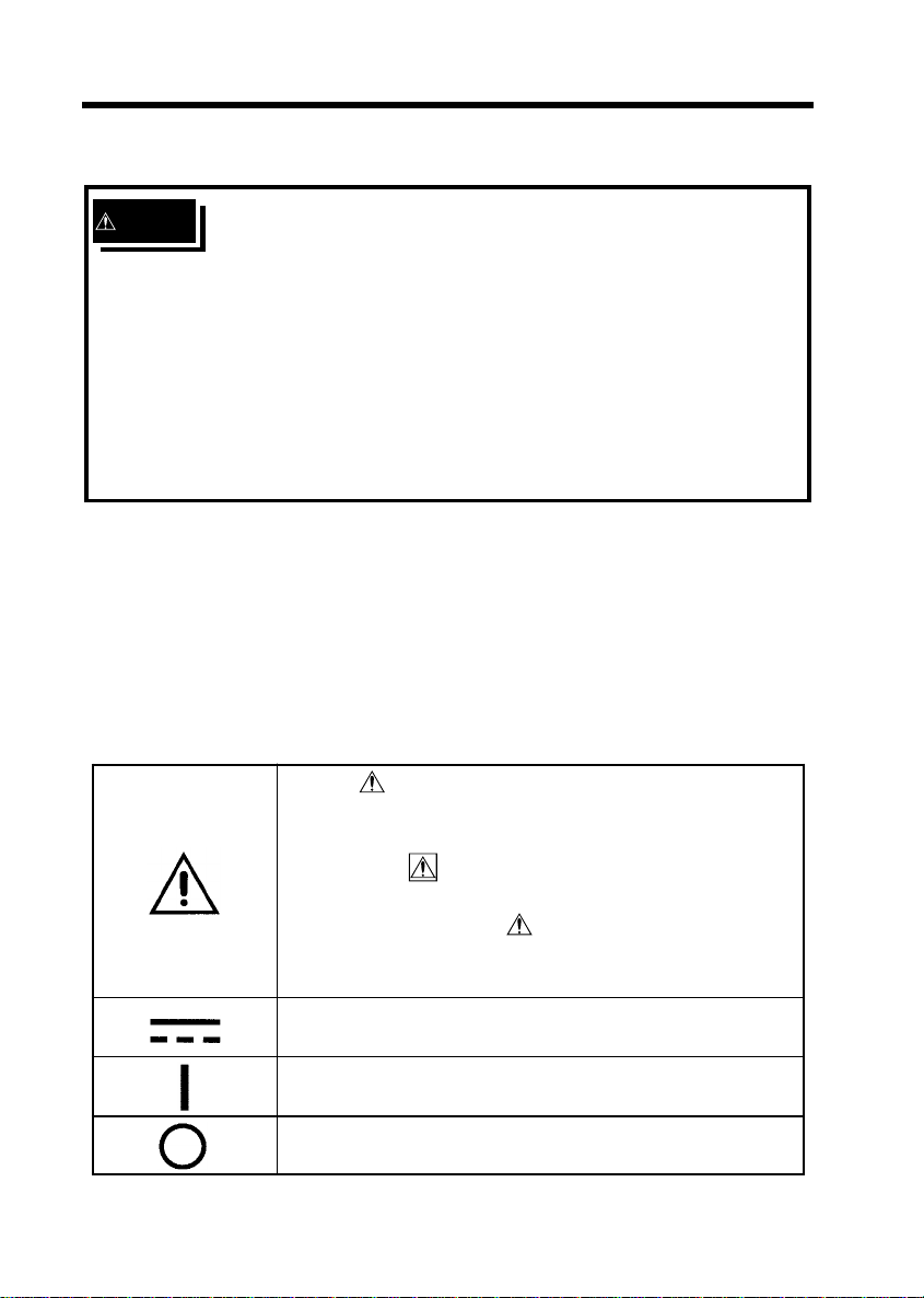
Safety
――――――――――――――――――――――――――――――――――
Measurement categories (Overvoltage categories)
This instrument complies with CAT I safety requirements.
To ensure safe operation of measurement instruments, IEC
61010 establishes safety standards for various electrical
environments, categorized as CAT I to CAT IV, and called
measurement categories. These are defined as follows.
CAT I : Secondary electrical circuits connected to an AC
electrical outlet through a transformer or similar
device.
CAT II : Primary electrical circuits in equipment connected
to an AC electrical outlet by a power cord (portable
tools, household appliances, etc.)
CAT III: Primary electrical circuits of heavy equipment
(fixed installations) connected directly to the
distribution panel, and feeders from the
distribution panel to outlets.
CAT IV: The circuit from the service drop to the service
entrance, and to the power meter and primary
overcurrent protection device (distribution panel).
Higher-numbered categories correspond to electrical
environments with greater momentary energy. So a
measurement device designed for CAT III environments can
endure greater momentary energy than a device designed
for CAT II.
Using a measurement instrument in an environment
designated with a higher-numbered category than that for
which the instrument is rated could result in a severe
accident, and must be carefully avoided.
Never use a CAT I measuring instrument in CAT II, III, or
IV environments.
The measurement categories comply with the Overvoltage
Categories of the IEC60664 Standards.