2
TAL 807 (L) Rev. 6 - 10042832
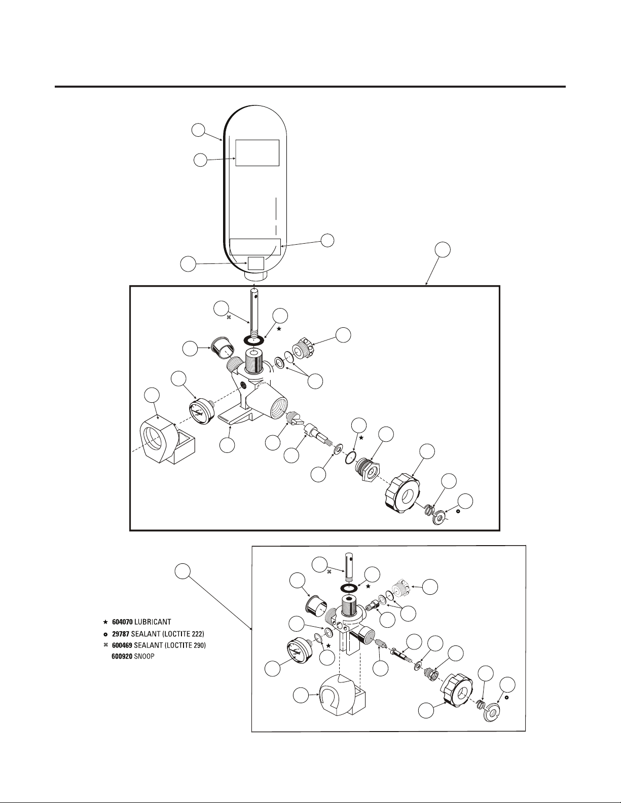
Item Part No. Description
80 872 3AL Aluminum, 5 cu ft.*
46 61 Hoop-wound, 5 cu ft.
807586 L-30 Stealth Carbon-wrapped
816115 L-30+ Stealth Carbon-wrapped, 60 cu ft.
807587 H-30 Stealth Carbon-wrapped, 5 cu ft.
807570 H- 5 Stealth Carbon-wrapped, 66 cu ft.
10035644
H- 5 Low-Profile, Stealth Carbon-wrapped, 66 cu ft.
1807588 H-60 Stealth Carbon-wrapped, 88 cu ft.
814806 3AL Aluminum, 5 cu ft.*
8111 Hoop-wound, 5 cu ft.
816 70 L-30 Stealth Carbon-wrapped
816 74 L-30+ Stealth Carbon-wrapped, 60 cu ft.
816 72 H-30 Stealth Carbon-wrapped, 5 cu ft.
816 73 H- 5 Stealth Carbon-wrapped, 66 cu ft.
10044832
H- 5 Low-Profile, Stealth Carbon-wrapped, 66 cu ft.
816 71 H-80 Stealth Carbon-wrapped, 88 cu ft.
2804 22 Warning Label
3471368 Label Lot No.
4 2845 Caution/Warning Label (3000 psig)
4888 4 Valve Assembly (2216 psig)
54 4884 Valve Assembly (3000 psig)
4888 Valve Assembly ( 500 psig)
680416 Cylinder Valve Inlet Tube
68542 O-Ring (2216 psig)
7633550 O-Ring (3000 psig)
630 26 O-Ring ( 500 psig)
68550 Safety Plug (2216 psig)
84 5636 Safety Plug (3000 psig)
473254 Safety Plug ( 500 psig)
968543 Drill Hex Head Socket Screw (Prior Design)
10 488858 Valve Insert Assembly
1533 Valve Insert Assembly
11 14438 Valve Stem (Prior Design)
48885 Valve Stem (Current Design)
12 488860 Valve Stem Washer
13 628 76 O-Ring (Current Design)
1 488862 Packing Gland (Current Design)
15 1728 Hand Wheel
16 83831 Spring
17 83731 Lock Nut
18 4 06 Protector Cap
Item Part No. Description
488771 Valve Body ( 500 psig) (Current Design)
19 488772 Valve Body (2216 psig) (Current Design)
45743 Valve Body (3000 psig) Valve Body (180°)
Valve Body (Prior Design)
501 Air Pressure Gauge (2216/3000 psig)
20 (Prior Design)
5278 Air Pressure Gauge (2216/3000 psig)
473250 Air Pressure Gauge ( 500 psig)
21 66835 O-Ring (Prior Design)
22 454544 Gland Ring (Prior Design)
23 801131 Gauge Guard
801140 Gauge Guard (Prior Design)
KITS
482225 Blow Out Disc Kit (2216 psig)
2 482226 Blow Out Disc Kit ( 500 psig)
4 4 28 Blow Out Disc Kit (3000 psig)
25 473 57 Packing Gland Kit (Prior Design)
CYLINDER VALVE ASSEMBLIES (LOW PRESSURE)
80 872 5 CU. FT. Aluminum (2216 psig) (Rated
30 Min.) (Current)
46 61 5.5 CU. FT. Hoop Wound Aluminum
(2216 psig) (Rated 30 Min.) (Current)
807586 66 CU. FT. Composite Carbon (2216 psig)
(Rated 30 Min.) (Current)
816115 60 CU. FT. Composite III Carbon
(3000 psig) (Rated 30 Min.) (Prior)
CYLINDER AND VALVE ASSEMBLIES (HIGH PRESSURE)
807587 5 CU. FT Composite Carbon ( 500 psig)
(Rated 30 Min.) (Current)
807570 66 CU. FT Composite Carbon ( 500 psig)
(Rated 5 Min.) (Current)
10035644 66 CU. FT. Composite Carbon ( 500 psig)
(Rated 5 Min.) (Current)
807588 88 CU. FT Composite Carbon/Fiberglass
( 500 psig) (Rated 60 Min.) (Current)
CYLINDER VALVE COMPONENTS