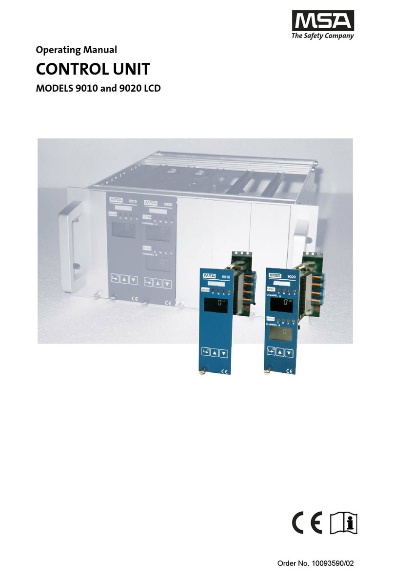
MSA 9010 SIL User manual

Company Reg No: SC260789 VAT Reg No: GB 828 8779 58
t: +44(0)141 771 7749
e: sales@frontline-safety.co.uk
Unit F, 230 Parkway Point, Springhill Parkway,
Glasgow Business Park, Glasgow, UK, G69 6GA
PRODUCT MANUAL
www.frontline-safety.co.uk

MSAsafety.com
Operating Manual
Model 9010/9020 SIL
Control Unit
Order No.: 10171754/00

MSA Europe GmbH
Schlüsselstrasse 12
8645 Rapperswil-Jona
Switzerland
www.MSAsafety.com
© MSA 2016. All rights reserved

3
GB
Model 9010/9020 SIL
Contents
1 Safety Regulations . . . . . . . . . . . . . . . . . . . . . . . . . . . . . . . . . . . . . . . . . . . . . . . . . . . . . . . . . . . . . . . . . . 5
1.1 Correct Use . . . . . . . . . . . . . . . . . . . . . . . . . . . . . . . . . . . . . . . . . . . . . . . . . . . . . . . . . . . . . . . . . . . 5
1.2 Liability Information . . . . . . . . . . . . . . . . . . . . . . . . . . . . . . . . . . . . . . . . . . . . . . . . . . . . . . . . . . . . . 6
2 Description. . . . . . . . . . . . . . . . . . . . . . . . . . . . . . . . . . . . . . . . . . . . . . . . . . . . . . . . . . . . . . . . . . . . . . . . . 7
2.1 Front Panel. . . . . . . . . . . . . . . . . . . . . . . . . . . . . . . . . . . . . . . . . . . . . . . . . . . . . . . . . . . . . . . . . . . 11
LEDS . . . . . . . . . . . . . . . . . . . . . . . . . . . . . . . . . . . . . . . . . . . . . . . . . . . . . . . . . . . . . . . . . . . . . . . 12
2.2 Display . . . . . . . . . . . . . . . . . . . . . . . . . . . . . . . . . . . . . . . . . . . . . . . . . . . . . . . . . . . . . . . . . . . . . . 12
Status of Control Unit . . . . . . . . . . . . . . . . . . . . . . . . . . . . . . . . . . . . . . . . . . . . . . . . . . . . . . . . . . . 13
2.3 Keypad . . . . . . . . . . . . . . . . . . . . . . . . . . . . . . . . . . . . . . . . . . . . . . . . . . . . . . . . . . . . . . . . . . . . . . 13
2.4 Input Signal Configuration . . . . . . . . . . . . . . . . . . . . . . . . . . . . . . . . . . . . . . . . . . . . . . . . . . . . . . . 14
2.5 Alarms and Overrange Functions. . . . . . . . . . . . . . . . . . . . . . . . . . . . . . . . . . . . . . . . . . . . . . . . . . 14
2.6 Configuration Jumpers . . . . . . . . . . . . . . . . . . . . . . . . . . . . . . . . . . . . . . . . . . . . . . . . . . . . . . . . . . 16
2.7 Output Signals . . . . . . . . . . . . . . . . . . . . . . . . . . . . . . . . . . . . . . . . . . . . . . . . . . . . . . . . . . . . . . . . 16
2.8 Digital Interfaces. . . . . . . . . . . . . . . . . . . . . . . . . . . . . . . . . . . . . . . . . . . . . . . . . . . . . . . . . . . . . . . 17
3 Installation . . . . . . . . . . . . . . . . . . . . . . . . . . . . . . . . . . . . . . . . . . . . . . . . . . . . . . . . . . . . . . . . . . . . . . . . 18
3.1 Mechanical Installation . . . . . . . . . . . . . . . . . . . . . . . . . . . . . . . . . . . . . . . . . . . . . . . . . . . . . . . . . . 18
3.2 Electrical installation. . . . . . . . . . . . . . . . . . . . . . . . . . . . . . . . . . . . . . . . . . . . . . . . . . . . . . . . . . . . 19
3.3 Initial System Check after Installation . . . . . . . . . . . . . . . . . . . . . . . . . . . . . . . . . . . . . . . . . . . . . . 25
4 Operation . . . . . . . . . . . . . . . . . . . . . . . . . . . . . . . . . . . . . . . . . . . . . . . . . . . . . . . . . . . . . . . . . . . . . . . . . 26
4.1 Start-Up . . . . . . . . . . . . . . . . . . . . . . . . . . . . . . . . . . . . . . . . . . . . . . . . . . . . . . . . . . . . . . . . . . . . . 26
4.2 Configuration Menu . . . . . . . . . . . . . . . . . . . . . . . . . . . . . . . . . . . . . . . . . . . . . . . . . . . . . . . . . . . . 27
4.3 Use of the Keys for Access to the Codes. . . . . . . . . . . . . . . . . . . . . . . . . . . . . . . . . . . . . . . . . . . . 27
4.4 Example for Use of the Keys for Access to the Access Codes . . . . . . . . . . . . . . . . . . . . . . . . . . . 28
5 Settings Parameters . . . . . . . . . . . . . . . . . . . . . . . . . . . . . . . . . . . . . . . . . . . . . . . . . . . . . . . . . . . . . . . . 30
5.1 Access Code 1 - Calibration. . . . . . . . . . . . . . . . . . . . . . . . . . . . . . . . . . . . . . . . . . . . . . . . . . . . . . 30
5.2 Access code 2 - Settings for Particular Operating Conditions . . . . . . . . . . . . . . . . . . . . . . . . . . . . 32
5.3 Access code 3 - Simulation and Functionality Operations Table . . . . . . . . . . . . . . . . . . . . . . . . . . 33
5.4 Access code 4 - Configuration . . . . . . . . . . . . . . . . . . . . . . . . . . . . . . . . . . . . . . . . . . . . . . . . . . . . 36
5.5 Access Code 6 - Basic Setup. . . . . . . . . . . . . . . . . . . . . . . . . . . . . . . . . . . . . . . . . . . . . . . . . . . . . 40
5.6 Access Code 7 - Peripheral Addresses . . . . . . . . . . . . . . . . . . . . . . . . . . . . . . . . . . . . . . . . . . . . . 41
5.7 Access code 52 - Input and Output Setup . . . . . . . . . . . . . . . . . . . . . . . . . . . . . . . . . . . . . . . . . . . 42
5.8 Access Code 53 - Default Settings. . . . . . . . . . . . . . . . . . . . . . . . . . . . . . . . . . . . . . . . . . . . . . . . . 43
5.9 Access Code 223 - "Admin" Password Setup . . . . . . . . . . . . . . . . . . . . . . . . . . . . . . . . . . . . . . . . 45
6 Calibration . . . . . . . . . . . . . . . . . . . . . . . . . . . . . . . . . . . . . . . . . . . . . . . . . . . . . . . . . . . . . . . . . . . . . . . . 46
6.1 9010 / 9020 SIL Module Calibration (for Passive Detectors Only) . . . . . . . . . . . . . . . . . . . . . . . . . 46
7 Maintenance. . . . . . . . . . . . . . . . . . . . . . . . . . . . . . . . . . . . . . . . . . . . . . . . . . . . . . . . . . . . . . . . . . . . . . . 48
8 Failure, Error and Status Messages . . . . . . . . . . . . . . . . . . . . . . . . . . . . . . . . . . . . . . . . . . . . . . . . . . . 49
8.1 901/9020 SIL - Failure Indications . . . . . . . . . . . . . . . . . . . . . . . . . . . . . . . . . . . . . . . . . . . . . . . . . 49
8.2 Error Indications . . . . . . . . . . . . . . . . . . . . . . . . . . . . . . . . . . . . . . . . . . . . . . . . . . . . . . . . . . . . . . . 52
9 Technical Data . . . . . . . . . . . . . . . . . . . . . . . . . . . . . . . . . . . . . . . . . . . . . . . . . . . . . . . . . . . . . . . . . . . . . 53

4
GB
Model 9010/9020 SIL
10 Markings, Certificates and Approvals . . . . . . . . . . . . . . . . . . . . . . . . . . . . . . . . . . . . . . . . . . . . . . . . . . 55
10.1 ATEX Directive . . . . . . . . . . . . . . . . . . . . . . . . . . . . . . . . . . . . . . . . . . . . . . . . . . . . . . . . . . . . . . . . 55
10.2 Special Conditions for Safe Use According to EU-Type Examination Certificate . . . . . . . . . . . . . 56
10.3 Special Conditions for the Safe Use of the Gas Warning Unit 9010/9020 in SIL Applications. . . . 57
10.4 Permitted Hardware/Software Versions . . . . . . . . . . . . . . . . . . . . . . . . . . . . . . . . . . . . . . . . . . . . . 58
11 Ordering Information. . . . . . . . . . . . . . . . . . . . . . . . . . . . . . . . . . . . . . . . . . . . . . . . . . . . . . . . . . . . . . . . 59
12 Appendix . . . . . . . . . . . . . . . . . . . . . . . . . . . . . . . . . . . . . . . . . . . . . . . . . . . . . . . . . . . . . . . . . . . . . . . . . 60
12.1 Alarms Sequence - Reset Modes. . . . . . . . . . . . . . . . . . . . . . . . . . . . . . . . . . . . . . . . . . . . . . . . . . 60
12.2 Outline Dimensions . . . . . . . . . . . . . . . . . . . . . . . . . . . . . . . . . . . . . . . . . . . . . . . . . . . . . . . . . . . . 62
12.3 Wall Mounted Version . . . . . . . . . . . . . . . . . . . . . . . . . . . . . . . . . . . . . . . . . . . . . . . . . . . . . . . . . . 63
12.4 External earth Connection . . . . . . . . . . . . . . . . . . . . . . . . . . . . . . . . . . . . . . . . . . . . . . . . . . . . . . . 63
12.5 4-20 mA Transmitter Connections . . . . . . . . . . . . . . . . . . . . . . . . . . . . . . . . . . . . . . . . . . . . . . . . . 64
12.6 Detectors Connection Data Sheet . . . . . . . . . . . . . . . . . . . . . . . . . . . . . . . . . . . . . . . . . . . . . . . . . 65

5
Safety Regulations
GB
Model 9010/9020 SIL
1 Safety Regulations
1.1 Correct Use
The Control Unit 9010/9020 SIL, hereafter called control unit, is designed for use as fixed gas
warning device. It is used to monitor industrial premises and installations for combustible, explo-
sive and toxic gases or air/vapour mixtures and for oxygen content.
The control unit provides:
• power for the connected detectors and transmitters
• signal conditioning and display of measured gas concentrations
• alarm thresholds
• outputs for external peripherals (horns, beacons. etc.)
• self-monitoring diagnostics
• 4-20 mA output (not intended for safety related applications).
The unit can be used for:
EX-monitoring: to protect operational plants and workers by continuously monitoring the atmo-
spheres for potentially explosive gases/vapours in air before they reach the lower explosion limit
– activating alarms and initiating risk aversion measures. The control unit is in conformance with
ATEX directive.
OX-monitoring to protect individuals by continuously monitoring the atmosphere for oxygen defi-
ciency or oxygen enrichment or monitoring the inerting of operational plants. The control unit is in
conformance with ATEX directive.
TOX-monitoring to protect individuals by continuously monitoring toxic gas concentrations in the
atmosphere.
If the set limit values are reached; e.g. maximum/minimum concentration in the atmosphere, an
alarm will be activated.
Typical applications are:
• Chemical and petrochemical industry
• Paint and solvent industry
• Gas-processing industry
• Wastewater treatment plants or similar municipal facilities
WARNING!
In case of operation with catalytic combustion detectors: To guarantee the unambiguity of catalytic
combustion detector operation, it must be made sure (e.g. by checking with hand-held test instru-
ments) each time before turning on the detectors and the system that the environmental atmo-
sphere to be monitored by the detectors does not contain dangerous gas concentrations of
combustible gases.
It is imperative that this operating manual be read and observed when using the device. In partic-
ular, the safety instructions, as well as the information for the use and operation of the device,
must be carefully read and observed. Furthermore, the national regulations applicable in the
user's country must be taken into account for a safe use.

6
Safety Regulations
GB
Model 9010/9020 SIL
WARNING!
This device is supporting life and health. Inappropriate use, maintenance or servicing may affect
the function of the device and thereby seriously compromise the user's life.
Before use the device operability must be verified. The device must not be used if the function test
is unsuccessful, it is damaged, a competent servicing/maintenance has not been carried out,
genuine MSA spare parts have not been used.
Alternative use, or use outside this specification will be considered as non-compliance. This also
applies especially to unauthorised alterations to the device and to commissioning work that has
not been carried out by MSA or authorised persons.
1.2 Liability Information
MSA accepts no liability in cases where the device has been used inappropriately or not as
intended. The selection and use of the device are the exclusive responsibility of the individual
operator.
Product liability claims, warranties and guarantees made by MSA with respect to the device are
voided, if it is not used, serviced or maintained in accordance with the instructions in this manual.

7
Description
GB
Model 9010/9020 SIL
2 Description
The control unit enables connection of one or two detectors/transmitters, depending on its design.
The board is available in two versions:
•Control Unit 9010 SIL for connecting one general purpose input (catalytic combustion
detector or semiconductor detector or 4/20 mA transmitter)
•Control Unit 9020 SIL for connecting two general purpose inputs (catalytic combustion detec-
tors, semiconductor detectors or 4/20 mA transmitters)
Both versions are available in the following installation options:
• 19” rack module - to be used as plug-in module into a standard 19” rack (Fig. 1 and Fig. 2)
• Wall mounted unit for direct wall installation (Fig. 3 and Fig. 4).
19010 rack board version 29020 rack board version
39010 wall mounted version 49020 wall mounted version

8
Description
GB
Model 9010/9020 SIL
The Control Unit 9010/9020 SIL fulfils the requirements of ATEX directive as well as SIL 2
requirements based on EN 61508 standard.
The control units connected to detectors or transmitters that operate in potentially hazardous
areas must be configured according to ATEX directive requirements for detection of combustible
gases or oxygen.
Besides the ATEX configuration, the control unit can be configured for the use of individual chan-
nels depending on different application requirements.
Main features of the control unit:
• Passive catalytic and semiconductor detectors or 4-20 mA transmitters using 2 or 3 wire
connection can be connected.
• Input can be configured as dual state (digital) inputs
• Front panel LCD display and four key keypad (up, down, ESC, Enter) for ease of configuration
and calibration. Specific messages on the display inform and identify any operational failure
and any erroneous data setting.
• 3 alarm thresholds (C- CAUTION, W- WARNING, A- ALARM) based on preset values.
• Intermittent module diagnostics for information on module status and drive failure relay in case
of module or connected detectors malfunction.
• Indication of output alarms via relay contacts.
• External horn can be connected.
• The control unit provides a 0(4)-20 mA output signal; it is independent for individual channels.
• The control unit can be fully parametrized via front panel keypad.
• Passwords and access codes prevent accidental or unwanted unit configuration.

9
Description
GB
Model 9010/9020 SIL
Symbols and Abbreviations Used in this Manual
The board is available in two versions:
Description
ACK Acknowledgement
EMC Electromagnetic Compliance
FS Full Scale
LED Light Emission Diode
LEL Lower Explosive Limit - measurement units for gas detection point detectors
LELm Lower Explosion Limit meter - measurement units for gas detection open path detec-
tors
PCB Printed Circuit Board
SPDT Single Pole Dual Throw
STEL Short Time Exposure Limit
TWA Time Weighted Exposure Limit
VAC Alternate Current Voltage
VDC Direct Current Voltage
SCADA Supervisory Control and Data Acquisition
PLC Programmable Logic Controller
DCS Distributed Control System
SIL Safety Integrity Level
Earth Terminal
Protective Conductor Terminal
Important Note
Caution, risk of danger (See note)

10
Description
GB
Model 9010/9020 SIL
19” Rack Module
Fig. 1 19" rack module
Heartbeat LED Indication Description:
Wall Mounted Unit
Fig. 2 Wall mounted unit
1 Front panel with display 8 Hardware revision information on the PCB
2 Module power supply 9 Configuration jumper (CV18)
3 ALARM relay 10 Configuration jumpers (CV22)
4 FAILURE relay 11 Ethernet connector (Modbus TCP)
5 WARNING relay 12 "Heartbeat" LED indication (Firmware)
6 HORN relay 13 USB connector (for MSA service only)
7 Backplane connector - Label with actual firmware version is
on the back
Red/green are fading on and off Firmware is running
LED is off Watchdog failure
1 Display board connector 2 Backplane terminal board
1
12
2
3
5
6
4
7
9
13
11 10
8
12

11
Description
GB
Model 9010/9020 SIL
2.1 Front Panel
Depending on configuration, there are 2 different front panels available for
9010 Module (1 display unit) and 9020 module (2 display units).
Fig. 3 9010 Fig. 4 9020
1 Status LEDs (red/yellow) 5 Site Information Tag
2 System Failure LED (yellow) 6 Display
3 POWER LED (green) 7 Keypad
4 Gas Information Tag 8 Approval label
1
6
2
3
4
5
7
8

12
Description
GB
Model 9010/9020 SIL
LEDS
Gas Information Tag
For specifying the gas type being monitored.
An individual gas name tag is available for each channel if Control Unit 9020 SIL is used.
Site Information Tag
For identifying the measuring site. It applies to both channels if Control Unit 9020 SIL is used.
2.2 Display
The control unit has a 4 digit back lit LCD for each measuring channel.
There is additional information available on the display besides the value of the measured gas
concentration:
Fig. 5 Display
Status LEDs
Red alarm status LEDs (C, W, A) for the optical indication of reaching the alarm
thresholds.
Yellow failure status LED (F) for the optical indication of a possible failure or
out-of-service condition.
Status LED information is available for both channels individually
if Control Unit 9020 SIL is used.
SYSTEM
FAILURE LED
The SYSTEM FAILURE LED lights up during system start and if an internal
system failure occurs.
The SYSTEM FAILURE LED information applies to both channels
if Control Unit 9020 SIL is used.
POWER LED
A green LED next to the keypad. It lights up if the device is turned on and it
blinks when entering an access code.
The POWER LED information applies to both channels if Control Unit 9020 SIL
is used.
1 Measured value
2 Measuring units
3 Important unit configuration settings (CAL, TIME OUT OFF, Alarm Delay C/W/A, Alarm Inhibit)
1
2
3

13
Description
GB
Model 9010/9020 SIL
Measured Values
The display shows the actual gas concentration. The decimal point position can be set in
Access Code No.4.
Measuring Units
The measuring units can be set to LEL, LELm, PPM, %Vol, g/m3 or no units.
For more information about measuring units setting, see chapter 5.4.
Access code 4 - Configuration operations.
Status of Control Unit
2.3 Keypad
ALARM INHIBIT
ALARM INHIBIT is blinking in the display of the channel with inhibited
alarms.
If inhibited the alarm relays will not be activated in case the measured
concentration reaches the alarm level.
For more information about ALARM INHIBIT see chapter 5.2 "Access
code 2 - Settings for Particular Operating Conditions".
ALARM DELAY
ALARM DELAY is displayed if Alarm delay is activated for the individual
channel.
For more information see chapter 5.4 "Access code 4 - Configuration".
TIME-OUT OFF
TIME-OUT OFF is displayed if the TIME-OUT function is disabled. The
TIME-OUT function checks if a front panel key is pressed (e.g. during
configuration of the unit.
For more information about TIME-OUT function see chapter 5.2 "Access
code 2 - Settings for Particular Operating Conditions".
CAL
The CAL indicator provides information about the pre-set calibration term
and about detector sensitivity reduction during calibration procedure.
CAL indicator starts blinking if the calibration pre-set time interval
expires.
CAL is steadily displayed if the detector signal during the calibration is
below 50 % of the signal achieved during the previous calibration.
For more information see chapter 5.1 "Access Code 1 - Calibration".
Enter key To select the access codes and
confirm data settings
UP key
For increasing the value to be
modified in the configuration
menu
Can be used for alarms acknowl-
edgement/horn silence and alarm
reset in normal operating mode.
Down key
For decreasing the value to be
modified in the configuration
menu
Can be used for alarms acknowl-
edgement/horn silence and alarm
reset in normal operating mode.
Escape key To leave the actual menu or
cancel the changes

14
Description
GB
Model 9010/9020 SIL
2.4 Input Signal Configuration
The input configuration is set in Access Code 52, P2, see chapter 5.7.
2.5 Alarms and Overrange Functions
The alarm set-points are:
•CAUTION (C) caution threshold
•WARNING (W) warning threshold
•ALARM (A) alarm threshold (STEL or TWA)
•Overrange (EEEE) indication on the display if the full scale is exceeded (>103 %)
Exceeding the alarm set-points will cause the relevant alarm LED as well as the digital output
(relay or opto-coupler) to be activated.
CAUTION, WARNING and ALARM Thresholds
The alarms can be configured in Access Code 4, which, besides setting the intervention thresh-
olds, allows the following configuration:
• setting alarm activation in case of rising or falling signal.
• setting the status of relay coils in normal conditions (energized or not energized).
Different reset modes:
• Automatic reset (1A)
• Automatic reset with memorization of alarm event (2A)
• Manual reset (1M)
• Manual reset with memorization of alarm event (2M)
For more information on the alarm reset modes see chapter 12.1.Acknowledging an alarm
(silencing the horn) and manual alarm reset can either be done with the UP or DOWN key on the
front panel or be performed remotely (see TERMINAL CONNECTIONS DIAGRAMS, Fig. 7 and
Fig. 8).
WARNING!
The Alarm set points are scaled in percentage related to the defined measuring range. It is neces-
sary to check C,W, A alarm thresholds after the measuring range is modified.
ATEX mode only: C, W, A alarm thresholds can be set within the interval 0 % - 100 % FS.
Overrange indication is always active.
In the ATEX mode, the W and A relays coil is normally energized.
STEL and TWA Alarms
In the non-ATEX mode, with the measurement unit PPM, it is possible to set alarms based on
15 min (STEL) average calculation and/or on 8 h (TWA) average calculation.
STEL Average CALCULATION
Average value of last 15 measurements (any negative values are considered as 0 ppm).
The value of the STEL average will be available after 15 min from start-up. The sampling time for
the calculation is 1 min.
TWA Average CALCULATION
Average value of last 480 measurements (any negative values are considered as 0 ppm).
The value of the TWA average will be available after 480 min (8 h) from start-up. The sampling
time for the calculation is 1 min.
OVERRANGE
The OVERRANGE function indicates when 103 % of the full scale is exceeded. Refer to the status
of alarms and outputs depending on the unit configuration below:

15
Description
GB
Model 9010/9020 SIL
A) Input Signal is Over 103 % FS
* Can be acknowledged by operator pressing UP or DOWN key
B) Input Signal Returns Back to Measuring Range Interval
* Can be acknowledged by operator pressing UP or DOWN key
The CAUTION set-point, which threshold can be set to100 % of full scale, can be used for the
remote OVERRANGE indication.
WARNING!
In case of an OVERRANGE signal, it is necessary to check that the area around a detector on site
is free from dangerous gas concentration for the specific channel before an alarm reset is
performed.
Failure Conditions
Besides the red alarm LEDs, the control units are equipped with a yellow LED (FAILURE) which
signals possible failures of control unit functions (individual for each channel when using a Control
Unit 9020 SIL).The remote indication is accomplished via a related relay (FAILURE), which is
equipped with two free voltage contacts connected in series to guarantee reliability of switching
function.The failure type is shown on the display, a list can be found in chapter 8.1.
SYSTEM failure condition is monitored by an internal watchdog and in case of any system
malfunction the SYSTEM failure LED and the Failure relay are activated.
Analogue output status in failure conditions follows a setting made in Access Code 4 P20.
Non ATEX mode ATEX Mode
Display "EEEE "EEEE"
C,W,A *Activated *Activated
FAILURE Activated Activated
HORN *Activated *Activated
4-20 mA Output As it is configured in Access Code 4, P20 22 mA
Non ATEX mode ATEX Mode
Display "EEEE"alternates
with actual measured value
"EEEE" stays displayed
until it is acknowledged manually
C,W,A
*Activated
stays activated until it is reset
manually
*Activated
stays activated until it is reset
manually
FAILURE In normal state
Activated
stays activated until it is reset
manually
HORN
*Activated
stays activated until it is reset
manually
*Activated
stays activated until it is reset
manually
4-20 mA Output Follows the input change stays at 22 mA until it is reset
manually
In the ATEX mode, the Failure relay coil is normally energized.
With Control Unit 9020 SIL, the failure is indicated once for both channels if output relays
are used.

16
Description
GB
Model 9010/9020 SIL
2.6 Configuration Jumpers
For setting some pre-defined basic features, configuration jumpers are used. There are two
jumpers available on the main board (see Fig. 5 for jumper location).
Jumper CV18 - for configuration of DC power mode (internal or external).
Jumper CV22 - for CAUTION output configuration if relays are used
For jumper identification on the main board refer to Fig. 5.
2.7 Output Signals
Relay Outputs
The control units are equipped with four SPDT relays 8A/250 VAC:
• 2 relays related to WARNING, and ALARM status,
• 1 relay related to FAILURE status
• 1 relay that can operate the external HORN.
For more information about backplane terminal board connection see chapter 3.2.
Voltage-free contacts must be used according to electrical characteristics are listed in chapter 9.
The control unit with relay outputs can be configured using Access Code 52: For more information
see chapter 5.7.
If the opto-isolated CAUTION output is used and 24 VDC external power supply is not available
then set CV22 in position 2-3 and CV18 in position 1-2.
Analog Outputs
The control unit provides independent analog outputs for each channel. The output signal can be
configured using Access Code 2 and Access Code 4.
0-20 mA, 4-20 mA, 20-0 mA or 20-4 mA output signal can be set. For more information see
chapter 5.2.
Jumper No. Position Function
CV18 1-2 Internal 24 VDC power supply is used to supply the external auxiliary
circuits (e.g. relays, interfaces, transmitters, etc.)
CV18 2-3 External 24 VDC power supply is used (e.g.: battery backup, power
supply modules, etc.)
Jumper No. Position Function
CV22 1-2 Opto-isolated CAUTION output needs the external negative on
terminal 7
CV22 2-3 Opto-isolated CAUTION output uses the negative as common to the
default board
CAUTION alarm is designed as an opto-isolated output only.
Common relay outputs are used for both channels related to Control Unit 9020 SIL.

17
Description
GB
Model 9010/9020 SIL
2.8 Digital Interfaces
RS485 Interface
The serial interface RS485 can be used for the connection with SCADA supervision system or
other PLCs, DCS, etc.
The data transmitted on RS485 is half duplex type (38400 / 9600 baud) with Modbus protocol.
See chapter 5.6 for RS485 interface setting.
Refer to Modbus documentation No.D0754156 which can be found on the enclosed CD.
USB Port
The control unit has the USB interface for connecting the control unit to the computer. The USB
interface is reserved for MSA service access only.
Contact MSA for any technical questions. For local MSA contacts go to our website
www.MSAsafety.com.
Ethernet Interface
The control unit has a build in web interface. The web interface allows the operator to see the
controller status. To access the web interface, enter the IP address of the control unit into the
address bar of a web browser. The default username "Customer" and the default password "MSA"
have to be entered to see all information.
See chapter 5.6 for Ethernet interface setting.
Ethernet connection is only available for the wall mounted version due to mechanical reasons.
WARNING!
For safety reasons, the 9010/9020 SIL Ethernet connection and the connected Modbus TCP
Master (SCADA system or PLC) must be used in an own, separated network.

18
Installation
GB
Model 9010/9020 SIL
3 Installation
WARNING!
The area where the 9010/9020 SIL control unit is installed must be outside of a hazardous area
Zone 0, 1 or 2 and it must be free of ignitable, explosive or corrosive gases. Detector installation
at the Control unit must be carried out according to relevant local and national regulation
(EN 60079-14).
The installation location for the control unit must be outside of any potentially explosive area and
free of corrosive gases. Detectors for use in the Ex area must have the appropriate Ex approval
and must be installed in accordance with all relevant local and national regulations.
The gas warning system must only be installed by qualified personnel after reading the relevant
documentation (instruction manual for selected detector or transmitter).
The correct assignment of each detector and control unit must be ensured during installation by
referring to the serial numbers indicated on the calibration data sheet provided by MSA.
3.1 Mechanical Installation
Depending on the version the control unit can be installed as a module in 19" rack or as a stand-
alone unit (wall mounted version).
Do not install the control unit in environments that are particularly humid, oxidizing, corrosive,
subject to notable vibrations or in which the temperature limits listed in the Technical Data chapter
are exceeded.
If installation is planned inside cabinets, the standards for maximum permissible temperature
must be observed. Cabinets must provide sufficient heat convection to dissipate heat from various
electronic components on the boards.
There must be sufficient space between the19” racks allowing a good air ventilation. Sufficient
space also needs to be left at the back of the rack to allowing a correct cables connection to the
backplane terminal boards.
The outline dimensions of the available 19" racks can be found in the Appendix. See chapter 12.2.
Backplane terminal unit screws, front panel screws (including blank panels) and rack mounting
screws (M6) must be tighten with a special torque moment in 19" rack.
• 0.3 Nm for backplane terminal screws
• 0.8 Nm for front panel screws
• 10 Nm for rack mounting screws (M6)
The outline dimensions of the available 19" racks can be found in the Appendix. See chapter 12.2.
Wall mounted unit installation instruction:
(1) Mark the holes as shown in chapter 12.3 for the four fixing screws.
(2) Drill four holes (diameter according to used screws).
(3) Remove the lid from the housing.
(4) Fix the control unit to the wall with appropriate screws.
(5) Close the lid with lid screws.
In case the PCB has to be removed (for example if M4 terminal access is needed) release the 3
fixing screws.When re-installing the PCB, tighten the fixing screws using a torque of 1,5 Nm.
Before starting the installation, check that the delivered components are complete and
correct by referring to the shipping documents.

19
Installation
GB
Model 9010/9020 SIL
Fig. 6 PCB fixing screws
3.2 Electrical installation
The installation location must be chosen in accordance with environmental conditions listed in
chapter 9 – Technical data.
WARNING!
The control unit must be installed in compliance with all applicable regulations, otherwise the safe
operation of the control unit is not guaranteed.
During installation, use the internal earth connection to ground the instruments.
If an external earth connection is permitted or demanded by the local authorities, it serves merely
as additional earthing (See Appendix 12Fig. 18).
The control units were tested and developed in compliance with the EMC directives and the
current standards EMC (EN 50270). In order to guarantee conformity with the EMC standards,
several rules need to be observed during the installation phase:
• Avoid installations in areas with a presence of strong electromagnetic fields.
• To connect control units to the main power supply, a failure-free ground or failure-free potential
bonding conductor must be provided.
• The user must ensure an appropriate supply voltage in accordance with EMC directives.
• The main supply source must not be subjected to voltage variations exceeding the limits spec-
ified in this manual.
• The main supply source must be free of any surges and sudden voltage changes due to heavy
electrical loads and disturbances caused by inductive or capacitive loads, false contacts and
strong electromagnetic interference
• All detector and control cables must be shielded. Shielded cables must have at least 80 %
coverage.
• Shielded cables must be laid in a group. If cable lengths are to be extended using terminal
boxes, the boxes must be shielded and the internal connections must be kept as short as
possible.
• If the devices are supplied using a DC power supply, the supply cable must be properly
shielded.
• Control and detector cables must be installed physically separate from power supply cables,
with a distance of at least 30 cm.
• External devices used (horns, beacons, motors, etc.) must be shielded from radio frequencies
and must conform to EMC directives.
• MSA cannot be held liable for malfunctions and/or damage caused by electrical disturbances
that are due to natural phenomena (e.g. lightning strikes).
This manual suits for next models
1
Table of contents
Other MSA Control Unit manuals
Popular Control Unit manuals by other brands

Balboa
Balboa MVP240 Reference card

Leonard
Leonard TM-186-30015050-PRV INSTALLATION ADJUSTMENT SERVICE

SEA
SEA SWING 2 DG R2F manual

Flow-Rite
Flow-Rite ProTimer Installation and operation instructions

Watts
Watts AMES 2000SS Series INSTRUCTION, INSTALLATION, MAINTENANCE AND REPAIR MANUAL

Sanyo
Sanyo VAC-60 instructions