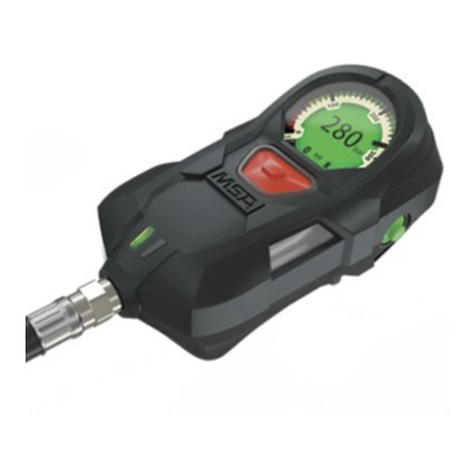
MSA M1 User manual

MSAsafety.com
Operating Manual
M1 Control Module
Integrated Personal Alert Safety System (PASS)
Order No.: 10205429/00

Schlüsselstrasse 12
8645 Rapperswil-Jona
Switzerland
© MSA 2019 All rights reserved

M1 Control Module 3
GB
Contents
1 Safety Regulations . . . . . . . . . . . . . . . . . . . . . . . . . . . . . . . . . . . . . . . . . . . . 4
1.1 Correct Use. . . . . . . . . . . . . . . . . . . . . . . . . . . . . . . . . . . . . . . . . . . . . 4
1.2 Liability Information. . . . . . . . . . . . . . . . . . . . . . . . . . . . . . . . . . . . . . . 4
2 Description . . . . . . . . . . . . . . . . . . . . . . . . . . . . . . . . . . . . . . . . . . . . . . . . . . 5
3 Installation . . . . . . . . . . . . . . . . . . . . . . . . . . . . . . . . . . . . . . . . . . . . . . . . . . 6
4 Use. . . . . . . . . . . . . . . . . . . . . . . . . . . . . . . . . . . . . . . . . . . . . . . . . . . . . . . . . 6
4.1 Before Use . . . . . . . . . . . . . . . . . . . . . . . . . . . . . . . . . . . . . . . . . . . . . 6
4.2 Switching on . . . . . . . . . . . . . . . . . . . . . . . . . . . . . . . . . . . . . . . . . . . . 6
4.3 Switching off/into Standby. . . . . . . . . . . . . . . . . . . . . . . . . . . . . . . . . . 6
4.4 Operating Modes . . . . . . . . . . . . . . . . . . . . . . . . . . . . . . . . . . . . . . . . 7
Service Mode . . . . . . . . . . . . . . . . . . . . . . . . . . . . . . . . . . . . . . . . . . . 7
4.5 Pressure Status Message . . . . . . . . . . . . . . . . . . . . . . . . . . . . . . . . . . 8
4.6 Display . . . . . . . . . . . . . . . . . . . . . . . . . . . . . . . . . . . . . . . . . . . . . . . . 9
Display Symbols . . . . . . . . . . . . . . . . . . . . . . . . . . . . . . . . . . . . . . . . . 9
4.7 Initiating Manual Alarm Calls during Use . . . . . . . . . . . . . . . . . . . . . . 9
4.8 Confirming Alarms . . . . . . . . . . . . . . . . . . . . . . . . . . . . . . . . . . . . . . .11
4.9 Battery Charging . . . . . . . . . . . . . . . . . . . . . . . . . . . . . . . . . . . . . . . . 12
4.10 Using a Safety Key . . . . . . . . . . . . . . . . . . . . . . . . . . . . . . . . . . . . . . 13
4.11 Personalization . . . . . . . . . . . . . . . . . . . . . . . . . . . . . . . . . . . . . . . . . 13
4.12 Bluetooth®Connection . . . . . . . . . . . . . . . . . . . . . . . . . . . . . . . . . . . 13
5 Cleaning and Maintenance . . . . . . . . . . . . . . . . . . . . . . . . . . . . . . . . . . . . 15
5.1 Cleaning . . . . . . . . . . . . . . . . . . . . . . . . . . . . . . . . . . . . . . . . . . . . . . 15
5.2 Maintenance . . . . . . . . . . . . . . . . . . . . . . . . . . . . . . . . . . . . . . . . . . . 15
Replacing the Battery . . . . . . . . . . . . . . . . . . . . . . . . . . . . . . . . . . . . 15
6 Troubleshooting . . . . . . . . . . . . . . . . . . . . . . . . . . . . . . . . . . . . . . . . . . . . . 17
7 Technical Data . . . . . . . . . . . . . . . . . . . . . . . . . . . . . . . . . . . . . . . . . . . . . . 17
8 Marking/Certification . . . . . . . . . . . . . . . . . . . . . . . . . . . . . . . . . . . . . . . . . 18
8.1 Marking . . . . . . . . . . . . . . . . . . . . . . . . . . . . . . . . . . . . . . . . . . . . . . . 18
8.2 Certification . . . . . . . . . . . . . . . . . . . . . . . . . . . . . . . . . . . . . . . . . . . . 19
9 Ordering Information . . . . . . . . . . . . . . . . . . . . . . . . . . . . . . . . . . . . . . . . . 21

M1 Control Module 4
Safety Regulations
GB
1 Safety Regulations
1.1 Correct Use
The M1 Control Module, in this manual also referred to as device, is a personal monitoring unit that
monitors the proper functioning of a respiratory protective device. It displays the current operating data
of the respiratory protective device and signals danger conditions (visually and acoustically).
It is imperative that this operating manual be read and observed when using the device. In particular,
the safety instructions, as well as the information for the use and operation of the device, must be care-
fully read and observed. Furthermore, the national regulations applicable in the user's country must be
taken into account for a safe use.
WARNING!
This product is supporting life and health. Inappropriate use, maintenance or servicing may affect the
function of the device and thereby seriously compromise the user's life.
Before use, the product operability must be verified. The product must not be used if the function test
is unsuccessful, it is damaged, a competent servicing/maintenance has not been made, genuine MSA
spare parts have not been used.
Alternative use, or use outside this specification will be considered as non-compliance. This also
applies especially to unauthorised alterations to the product and to commissioning work that has not
been carried out by MSA or authorised persons.
1.2 Liability Information
MSA accepts no liability in cases where the device has been used inappropriately or not as intended.
The selection and use of the device are the exclusive responsibility of the individual operator.
Product liability claims, warranties and guarantees made by MSA with respect to the device are voided,
if it is not used, serviced or maintained in accordance with the instructions in this manual.

M1 Control Module 5
Description
GB
2 Description
Fig. 1 Overview M1 Control Module
The M1 Control Module (see Fig. 1) is connected at the end of the high pressure gauge line of an appli-
cable MSA SCBA.
The device monitors the proper functioning of the respiratory protective device and signals danger
conditions (visually and acoustically). The digital display shows the current operating data of the respi-
ratory protective device, especially the pressure level which is also visible via the mechanical gauge.
In addition, the device automatically triggers an alarm if the apparatus user is not moving and provides
the opportunity for manual alarm triggering.
Green, yellow and red LEDs - buddy lights - mounted on both sides of the device indicate the pressure
state of the device. In the event of pressure alarm, motionless alarm or a manual alarm activation via
button, bright red buddy lights flash highly visible.
The device is equipped with an internal data memory for saving the operational data for more than 30
sessions with up to 20 min working time.
An RFID reader is located in the head of the device to read M1 TAGs for personalizing the device.
1 RFID Reader 6 Mechanical gauge with needle
2 Integrated display 7 Piezo sound generator and safety key port (acces-
sible from both sides)
3 Mode button (on both sides) 8 Alarm button
4 Buddy lights (on both sides) 9 Battery state LEDs
5 Rubber boot
3
1
4
6
8
9
2
7
5

M1 Control Module 6
Installation
GB
3 Installation
Installations can only be done by certified MSA technicians outside of hazardous areas.
4Use
4.1 Before Use
Before using the device, it is recommended to perform a short check to test for any leakage in the
system.
(1) Open compressed air cylinder.
(2) When device is started, close compressed air cylinder.
(3) Double press the alarm button.
4.2 Switching on
(1) Open compressed air cylinder.
If pressure < 30 bar, the device does not start up.
If pressure ≥30 bar, the device starts up.
4.3 Switching off/into Standby
The device is considered to be “off” when in Standby mode and monitoring the pressure level exclu-
sively. It is only possible to switch into Standby mode in the pressure-free status which is a measured
pressure below 15 bar.
To switch into Standby mode:
(1) Close the valve(s) of the compressed air cylinder(s) and vent the compressed air breathing
apparatus via the lung governed demand valve (see operating manual for compressed air
breathing apparatus).
An acoustic signal occurs between 60 and 0 bar.
(2) Push one of the mode buttons twice.
The pressure alarm turns off.
(3) Push one of the mode buttons twice.
An acoustic signal occurs.
The device turns into Standby mode.
Completely switching off the device is only possible by removing the battery.
The display turns white, shows the actual pressure and a progress bar.
If a green tick is displayed and the device turns on, the device can be used.
If a red cross is displayed, usage of the device is not recommended. Return the device to
a technical expert for check.
Electronic component check is performed:
All LEDs are flashing once, an acoustic signal occurs and the display lights up. The device is
ready for use.
If red LEDs light up and low battery symbol is displayed, the battery capacity might be to
low, see section 4.9 "Battery Charging".

M1 Control Module 7
Use
GB
4.4 Operating Modes
Service Mode
To activate the Service Mode:
(1) Press one of the green buttons longer than 5 sec.
The Service mode is activated.
(2) Use the green mode buttons to switch between the separate menu and submenu options.
For more information, see MSA A2 Software.
Mode Description
Standby Mode The display is turned off and the device only monitors the pressure level. To leave
this mode, pressurize the device.
Reading Mode This mode is used before device start-up to read in information stored on a TAG,
see section 4.11 "Personalization".
Scout Mode
The device is turned on and monitors the proper functioning of the SCBA.
The LEDs indicate the battery life and the buddy lights indicate the pressure level
in the compressed air cylinder.
By pressing one of the green mode buttons, the user can switch between the
pressure level and the remaining time display.
Service Mode This mode can be used in combination with MSA A2 Software to change device
settings and read out log memory.
Menu
About this M1 M1 Device Serial Number
Pressure Sensor S/N
Hardware
Main Module Application
Firmware Updater
Bootloader
Display Module Application
Bootloader
Hardware
Long Range Radio Version
Serial
Status System Pressure
Date
Errors
Main Battery State of Charge
Production Date
Config Rev.
Service Info On Pressure
Since Last Service
Last Service
Shut down

M1 Control Module 8
Use
GB
4.5 Pressure Status Message
While operating in Scout mode, the device makes an acoustic sound at the following pressure thresh-
olds:
• 1st pressure threshold – Single beep (standard setting: 200 bar)
• 2nd pressure threshold – Double beep (standard setting: 100 bar)
• Low pressure threshold – Double beep (60 bar) repeated until confirmed, see section 4.8
"Confirming Alarms"
These thresholds, except from the low pressure warning, can be changed using the MSA A2 Software
in combination with a Bluetooth enabled PC.
See MSA A2 Software for more details.
Cylinder Pressure Display
The cylinder pressure is displayed via the integrated mechanical gauge and additionally displayed on
the integrated display. Current pressure can be read from both, the gauge or display.
The following display thresholds represent the standard setting and, excluding the < 60 bar threshold,
can be changed using MSA A2 Software in combination with a Bluetooth enabled PC.
See MSA A2 Software for more details.
Pressure level in compressed air cylinder Display Buddy lights
> 100 bar green
between 100 bar and > 60 bar yellow
<60bar red

M1 Control Module 9
Use
GB
4.6 Display
Illuminating the Display during Operation
(1) Lift up the device over an angle of 45°.
The display turns on.
Display Symbols
4.7 Initiating Manual Alarm Calls during Use
The full alarm can be triggered manually by the user. This can be done during use as well as in Standby
mode and even without any pressure in the system.
Initiating a manual alarm:
(1) Press the manual alarm button until the alarm sounds and buddy lights are turned on.
The device is activated in full alarm.
Alarm States and Indication Display
Symbol Description
Bluetooth connection active
Radio connection active
Battery full
Battery half empty
Battery empty
Safety key inserted
Alarm Display View Display and Buddy Lights Acoustic
1st threshold
Display is lighted green,
Buddy lights are blinking
green every 20 sec
1Beep
2nd threshold
Display is lighted yellow,
Buddy lights are blinking
yellow every 6 sec
2Beep
Low pressure
warning (≤60 bar)
Display is lighted red,
Buddy lights are blinking red 2Beep
Battery warning Bottom red 1 Beep
repeatedly

M1 Control Module 10
Use
GB
For confirmation of alarms see section 4.8 "Confirming Alarms".
Motion pre-alarm Display is lighted red,
Buddy lights are blinking red
Increasingly
louder consecu-
tive variable
tones
Motion and manual
alarm
Display is lighted red,
Buddy lights are blinking red Distinct pattern
Evacuation alarm
Withdrawal alarm
Freefall alarm
Overhaul error
alarm
Alarm Display View Display and Buddy Lights Acoustic
The thresholds, except from the low pressure warning, can be changed using the MSA
A2 Software in combination with a Bluetooth enabled PC.
See MSA A2 Software for more details.

M1 Control Module 11
Use
GB
4.8 Confirming Alarms
The user can confirm an alarm after it is triggered as follows:
Once an alarm has been confirmed, the device changes the main display view back to review main
information in combination with a reminder symbol below the main information.
Alarm Confirmation Display Symbol
1st threshold Not necessary, since short acoustic signal.
2nd threshold Not necessary, since short acoustic signal.
Low pressure
warning (≤60 bar)
Confirmation only possible when pressure < 15 bar: Press
one of the mode buttons twice.
Pneumatic whistle of SCBA cannot be confirmed. Alarm will
continuously appear.
Battery warning Recharge/exchange batteries – outside of hazardous area
only.
Manual alarm Press one of the mode buttons twice.
Motion pre-alarm Move the device.
Motion alarm Press one of the mode buttons twice.
Evacuation alarm Press one of the mode buttons twice.
Withdrawal alarm Press one of the mode buttons twice.
Freefall alarm Press one of the mode buttons twice.

M1 Control Module 12
Use
GB
4.9 Battery Charging
Charging the Battery
WARNING!
Do not charge the battery in hazardous areas.
Charge battery only with MSA approved charger.
WARNING!
The magnetic field of the battery charger can disturb pacemaker operation and result in serious injury
or death.
Keep pacemaker and similar devices more than 10 cm away from the battery charger.
NOTICE
Charge the battery only in a control module which is turned off.
If a battery is detected as empty by the control module, charge it promptly.
Charge the battery in a temperature range between 5 °C to 40 °C.
Charge the battery completely before first use.
Charge the battery completely if it is stored for more than 2 months.
Charging the battery within the device
(1) Connect the power supply to the power outlet and to the charging adapter.
(2) Connect the charging adapter on the back of the battery pack.
a) Make sure the charging adapter is aligned correctly and the contacts are free of dirt.
Charging is indicated by the green status LED on the front of the device:
Charging: green blinking every 3 sec.
Charging 100%: green blinking every 45 sec.
The battery life of the device is indicated as follows:
Battery is OK The device starts in Scout mode. The battery state LED blinks green for
100 ms every 45 seconds.
Battery is empty
In Standby mode:
The battery state LED blinks red for 100 ms every 30 seconds.
The battery must be recharged or exchanged.
During start-up:
The device does not start properly. The buddy lights and the battery state
LED lighten up red, display shows battery alarm icon and an acoustic
signal sounds.
The battery must be recharged or exchanged.
If the device does not start even if a battery is connected, the battery must
be recharged or exchanged.

M1 Control Module 13
Use
GB
4.10 Using a Safety Key
The device can be used with a safety key (Part Number 10186697).
Activation and Deactivation of Motion Detection
The device automatically detects if a key is placed in the safety key port.
If a key is detected during start-up, the motion detection is deactivated and can be activated by
removing the key.
To deactivate Motion Detection:
(1) Before start-up, push the key in the safety key port of the device.
Motion Detection is deactivated.
All warnings and alarm sounds are deactivated.
To activate Motion Detection:
(1) Remove the key from the safety key port of the device.
Removal is confirmed with a single sound signal.
Motion Detection is activated.
All warnings and alarm sounds are activated.
Muting Alarms during Rapid Intervention Team (RIT) Missions
The key can be used during RIT missions to mute device alarms.
(1) In alarm state, push the key in the safety key port of the device.
Active alarms are muted.
Pressure warnings and pressure alarm sounds will still occur.
4.11 Personalization
In the Reading mode, the device can be personalized with an M1 TAG to support:
• User name
• Team information
• Preferred Base ID
To activate the Reading Mode:
(1) In Standby mode, press both green mode buttons until the Reading mode is started.
The display shows a progress bar to indicate the reading time slot.
(2) Place an M1 Tag in front of the RFID reader.
Successful reading: display shows the read information or positive reading icon depending
on read information.
Non successful reading: sound and an error symbol occur.
Tags can be created using the M1 TAG programming kit (Part Number 10199159) in combination with
the MSA A2 Software. See A2 Software manual for detailed description.
4.12 Bluetooth®Connection
Reading out the Device using a Bluetooth enabled PC
It is possible to read out the data from the M1 Control Module. Settings can be changed to a certain
extent and copied back to the device. The device can be read out while the Service mode is active and
a Bluetooth connection is enabled. This can be done after the MSA A2 Software is installed on the PC.
See MSA A2 Software manual.
The device can be paired via Bluetooth with other supported portable devices, e.g. ALTAIR 5X.
For information on supported gas detectors and sensors see relevant reference sheet.

M1 Control Module 14
Use
GB
For pairing instructions see operating manual of the relevant gas detector.
To enable Bluetooth functionality with MSA gas detectors (described for the ALTAIR 5X)
(1) Power on the MSA gas detector per the device instructions.
(2) Wait for the sensor warm-up phase to complete.
Due to the device calibration and start up times, MSA recommends powering on the gas detector
device first. Allow the gas detector to completely start up before moving on to the next step.
The device is ready for pairing once the Blue LED begins to blink quickly.
(3) Open compressed air cylinder. Wait until device has started up completely and is ready for use.
(4) Activate Reading mode of the M1 Control Module:
a) Press both green mode buttons until the Reading mode is started.
(5) Place the RFID chip of the gas detector onto the RFID
reader of the M1 Control Module.
a) The gas detector RFID chip location differs
depending on which model is in use.
b) The ALTAIR 5X RFID tag is located under the
MSA logo on the front of the device.
A green RFID icon will display on the M1 Control
Module.
(6) Accept the pairing request when it is displayed on the
gas detector.
The random number appearing below the pairing
request is not needed and can be ignored.
(7) The gas detector is now successfully paired to the M1
Control Module.
A successful Bluetooth wireless connection will
result in a slow blinking BLUE LED on the
ALTAIR 5X and a blue Bluetooth icon on the M1
Control Module display.
If the pairing process is unsuccessful, there will be
no slow blinking LED on the gas detector and the
steps above will need to be repeated.

M1 Control Module 15
Cleaning and Maintenance
GB
5 Cleaning and Maintenance
5.1 Cleaning
WARNING!
Do not use any organic cleaning material for the cleaning of the individual components, such as nitro
thinners, alcohol, white spirit, petrol etc.
NOTICE
The device shall not be removed from pneumatics and needs to be pressurized > 60 bar during (hand)
washing. Otherwise, ingress of water may damage the system or any components.
The device components should be cleaned after each operation and, if badly contaminated, with a
damp cloth (tepid water) and a little detergent.
For mechanical washing, follow detailed washing instructions for self-contained breathing apparatus
and lung governed demand valves.
The battery should always be connected to the device and the battery U-clip should be in the device.
Use the safety key to mute alarms.
5.2 Maintenance
The device is largely maintenance-free. It is recommended that the device is subject to regular visual
inspections to check whether there are any faults or damage.
If there are any faults, the device must be replaced. The device must not be repaired by the user.
Repairs must only be carried out by the manufacturer or by a repair service authorized by the manu-
facturer.
Maintenance and Test Schedules
Follow the SCBA guidelines for testing and maintenance.
Replacing the Battery
Due to storage and delivery times, it might be necessary to exchange batteries before putting the
device into first service.
The charging status of the batteries is monitored by the device. Low battery conditions can be
recognised by the user, see section 4.9 "Battery Charging".
Use approved batteries only.
The operational time might vary depending on ambient conditions and usage.
WARNING!
Remove battery if device is stored for more than six months.
Never change batteries in hazardous areas.
Type of work After use Every
10 years
Cleaning X
Recommended basic overhaul by manufacturer X

M1 Control Module 16
Cleaning and Maintenance
GB
WARNING!
Avoid short circuits between the electronic contacts of the battery pack.
Never use or charge batteries which are visibly damaged.
WARNING!
Only use fully charged batteries. Do not use batteries that trigger a battery alarm. Otherwise, the full
functionality of the device is not ensured.
NOTICE
Do not damage the battery. Be especially cautious with the exposed battery contacts.
Avoid condensed water on the inner electronic contacts of the battery pack.
Clean the inner electronic contacts only dry without the help of chemical cleaning compounds.
Otherwise, the full functionality of the device is not ensured.
Exchanging the battery
(1) Remove U-clip from housing completely.
(2) Pull battery carefully out of its compartment by lifting the exposed end.
(3) Move battery out of the rubber boot.
(4) Slide new battery underneath the rubber boot.
(5) Push the exposed battery end down towards the device.
(6) Push U-clip completely into housing.
Rubber Boot Exchange
The rubber boot must be exchanged from authorized workshop personnel only.
If the device is removed and reattached to the SCBA, the SCBA has to be tested following the SCBA
testing guidelines.

M1 Control Module 17
Troubleshooting
GB
6 Troubleshooting
7 Technical Data
Error Remedy
Battery communication error:
The error code 0333 is shown on the display.
If the error occurs during start-up, remove and
reinsert battery.
If the error code still shows, replace the battery.
Any other error Usage of the device is not recommended. Return
device to an MSA service center.
High pressure : 200 bar resp. 300 bar
Operating : -30 °C to +60 °C
Storage : 0 °C to +40 °C
Dimensions : Length: 156 mm
Width: 78 mm
Height: 71 mm
Weight : 350 g (without M1 Battery Pack)
500 g (with M1 Battery Pack)
Ingress protection : IP66/67
Bluetooth BR/EDR/LE
Operation frequency range : 2402 MHz...2480 MHz
Max. emission power : +10 dbm (10 mW)
Near field radio
Operation frequency range : 13.553 MHz...13.567 MHz
Max. emission power : 100 mW

M1 Control Module 18
Marking/Certification
GB
8 Marking/Certification
8.1 Marking
Fig. 2 Example for type label, M1 Control Module (device label may vary)
Fig. 3 Example for type label, M1 Battery Pack (device label may vary)
1 CE marking
2 ATEX information
3 Serial number consisting of:
• Device ID (e.g. “A” for main device, “B” for battery pack etc.)
• Production year, two digits (e.g. 19)
• Production week, two digits (e.g. 06)
• Consecutive number (e.g. 001)
4 Address of manufacturer
M1 Control Module
IECEx BVS 19.0048
BVS 19 ATEX E 053
Ex ia IIC T4 Ga
II 1G Ex ia IIC T4 Ga
-30°C ≤Ta ≤+60°C
MSA EUROPE GmbH
Schlüsselstrasse 12
8645 Rapperswil-Jona
CH - Switzerland
SN: A1906001
0158
1
2
3
4
0158
M1 Battery Pack
IECEx BVS 19.0048
BVS 19 ATEX E 053
Ex ia IIC T4 Ga
II 1G Ex ia IIC T4 Ga
-30°C ≤Ta ≤+60°C
MSA EUROPE GmbH
Schlüsselstrasse 12
8645 Rapperswil-Jona
CH - Switzerland
WARNING: USE ONLY WITH MSA M1 CONTROL MODULE
USE ONLY MSA APPROVED CHARGER
SN: B1906001
Li-Ion 7,4VDC, 2.2Ah, Um=15,2VDC
1
2
3
4

M1 Control Module 19
Marking/Certification
GB
8.2 Certification
The Declaration of Conformity can be found under the following link: https://MSAsafety.com/DoC
Marking, Certificates and Approvals according to the Directive 2014/34/EU (ATEX) and National
Standards
Approvals
0158
PPE EN 137:2007, type 2
DEKRA DEKRA Testing and Certification GmbH
Notified Body number: 0158
Manufacturer:
MSA Europe GmbH
Schlüsselstr. 12
CH - 8645 Rapperswil-Jona
Product: M1 Control Module
EU-Type
Examination Certificate: BVS 19 ATEX E 053
Standards: EN IEC 60079-0: 2018,
EN 60079-11: 2012
Marking: II 1G Ex ia IIC T4 Ga
-30 °C Ta +60 °C
Battery M1 Battery Pack
II 1G Ex ia IIC T4 Ga
-30 °C Ta +60 °C
Special Conditions for Safe Use: None
Quality Assurance
Notification: 0158
Year of Manufacture: see Label
Serial No.: see Label

M1 Control Module 20
Marking/Certification
GB
Marking and Certificates according to IECEx
Manufacturer:
MSA Europe GmbH
Schlüsselstr. 12
CH - 8645 Rapperswil-Jona
Product: M1 Control Module
IECEx-Type
Examination Certificate: IECEx BVS 19.0048
Standards: IEC 60079-0: 2017
IEC 60079-11: 2011+Cor.:2012
Marking: Ex ia IIC T4 Ga
-30 °C Ta +60 °C
Battery: M1 Battery Pack
Ex ia IIC T4 Ga
-30 °C Ta +60 °C
Special Conditions for Safe Use: None
Quality Assurance
Notification: 0158
Year of Manufacture: see Label
Serial No.: see Label
Other manuals for M1
9
Table of contents
Other MSA Control Unit manuals