manuals.online logo
Brands
  1. Home
  2. •
  3. Brands
  4. •
  5. MSW
  6. •
  7. Bicycle Accessories
  8. •
  9. MSW MINIAC User manual

MSW MINIAC User manual

26441 3/18 | 85-000862_INST_C
MINIAC SPEED & CADENCE SENSOR INSTRUCTIONS
6400 WEST 105TH STREET // BLOOMINGTON, MN 55438 // 1-855-883-6563 // WWW.MSWBIKE.COM
Thank you for purchasing an MSW®Speed and Cadence Sensor!
At MSW®we believe that having essential accessories makes a good
ride great.
WARNING: Cycling can be dangerous. Bicycle products should
be installed and serviced by a professional mechanic. Never modify your
bicycle or accessories. Read and follow all product instructions and warnings
including information on the manufacturer’s website. Inspect your bicycle
before every ride. Always wear a helmet.
For additional product and safety information go to: www.mswbike.com/safety.
COMPATIBILITY AND INTENDED USE
The MSW Speed and Cadence Sensor is compatible with 2.4g digital wireless
cycling computers. They need to have the capability to accept speed and
cadence data.
The MSW Miniac Speed and Cadence Sensor is intended for use
on roads and paved trails as well as ASTM Condition 2 use.
This includes smooth paved roads, unpaved and gravel roads,
and trails with moderate grades where loss of contact with
ground may occur but drops are less than 6" (15cm).
INCLUDED PARTS
Please check that all the following items have been included with the cycle
computer before starting.
A Sensor
B Rubber shim
C. Wheel magnet
D. Cadence magnet
E. Zip ties
F. Rubber O-ring
INSTALLATION
MOUNTING THE SENSOR
The sensor is mounted on the non-driveside chainstay, just behind the bottom
bracket. The distance between the computer head unit at the handlebar and
the sensor should not exceed 150cm.
The larger part of the sensor reads the cadence magnet to register cadence,
etc. The adjustable arm of the sensor unit registers speed, distance, etc.
The larger part of the sensor faces the front of the bike, and the adjustable arm
faces the back and sits along the inside of the chainstay. Loosen the knurled
dial in front of the adjustable arm to rotate it in the optimal position (fig. 1).
Do not tighten it until the optimal position has been determined.
Place the included rubber pad between the sensor and the chainstay. The sensor
is attached using two included zip ties, but do not fully tighten them until the
wheel and cadence magnets are in place, and the adjustments that yield the best
readings are made between the sensor, sensor arm, and the magnets (fig. 2).
The distance between the cadence magnet and the sensor, and between
the rear wheel magnet and the sensor arm should not exceed 3mm.
MOUNTING THE CRANK AND WHEEL MAGNETS
1. Place the cadence magnet on the inside of the crank arm 2 to 3cm up the
arm from the pedal spindle and zip tie it in place.
2. Position the larger part of the sensor close enough to the crank arm that the
required distance between it and the cadence magnet is achieved (fig. 3).
Checking operation of the sensor is most easily done with the bike
in a repair stand rather than doing it while riding.
3. Using this sensor placement as a guide, position the wheel magnet in the
approximate area that it will pass the sensor arm on the inside of the
chainstay. The wheel magnet is tightened to the spoke by threading it into
the magnet bracket that sits behind the spoke (fig. 4).
4. Holding the larger part of the sensor in place with one hand, rotate the arm
of the sensor so that the required distance between it and the wheel
magnet is achieved.
Bracket
Nylo n Ties
Rubber
Bracket
Cycle Computer
Rubber Pad
Bracket
Cycle Computer
1–3mm
1–3mm
Spoke
Chainstay
(non-driveside)
Rear
Wheel
Front
Wheel
Cadence Sensor Speed Sensor
Zip Tie Cadence Magnet
Crank Pedal
Cadence Sensor
1–3mm
Time Average Speed Maximum Speed Distance
Odometer Calorie Consumption
Average Cadence Maximum Cadence Trip Cadence
Unit Tire size
Time
Time
Gender / Weight ODO Temperature
Gender / Weight
M (MODE): Next option
C: Next setting
[SET]: Change the value
Temperature °C/°F
H1 (Male)
H2 (Female)
WS: 0100–2999mm
KM/H+Kg+KM
M/H+Lb+KM
12H/24H
[SET]
Weight: 20–150Kg
44–330 lb
3 seconds
Searching for 30 seconds
Press and hold mode
key for 3 seconds
After 5 seconds of receiving
code from the sensor
PAIRED NOT PAIRED
C BUTTON
MODE BUTTON
M M
C
M/CM/C
M/C
M/CM/C
M
M
M
MMM
[SET][SET]
C
M/C Save and Exit
Hour (1–24)
Minute (0–59)
Second (0–59)
>M
[SET]
C C
C
C
PRESS
Not paired:
• Check sensor alignment
• Check battery
Figure 1
Figure 2
Bracket
Nylo n Ties
Rubber
Bracket
Cycle Computer
Rubber Pad
Bracket
Cycle Computer
1–3mm
1–3mm
Spoke
Chainstay
(non-driveside)
Rear
Wheel
Front
Wheel
Cadence Sensor Speed Sensor
Zip Tie Cadence Magnet
Crank Pedal
Cadence Sensor
1–3mm
Time Average Speed Maximum Speed Distance
Odometer Calorie Consumption
Average Cadence Maximum Cadence Trip Cadence
Unit Tire size
Time
Time
Gender / Weight ODO Temperature
Gender / Weight
M (MODE): Next option
C: Next setting
[SET]: Change the value
Temperature °C/°F
H1 (Male)
H2 (Female)
WS: 0100–2999mm
KM/H+Kg+KM
M/H+Lb+KM
12H/24H
[SET]
Weight: 20–150Kg
44–330 lb
3 seconds
Searching for 30 seconds
Press and hold mode
key for 3 seconds
After 5 seconds of receiving
code from the sensor
PAIRED NOT PAIRED
C BUTTON
MODE BUTTON
M M
C
M/CM/C
M/C
M/CM/C
M
M
M
MMM
[SET][SET]
C
M/C Save and Exit
Hour (1–24)
Minute (0–59)
Second (0–59)
>M
[SET]
C C
C
C
PRESS
Not paired:
• Check sensor alignment
• Check battery
Bracket
Nylo n T ies
Rubber
Bracket
Cycle Computer
Rubber Pad
Bracket
Cycle Computer
1–3mm
1–3mm
Spoke
Chainstay
(non-driveside)
Rear
Wheel
Front
Wheel
Cadence Sensor Speed Sensor
Zip Tie Cadence Magnet
Crank Pedal
Cadence Sensor
1–3mm
Time Average Speed Maximum Speed Distance
Odometer Calorie Consumption
Average Cadence Maximum Cadence Trip Cadence
Unit Tire size
Time
Time
Gender / Weight ODO Temperature
Gender / Weight
M (MODE): Next option
C: Next setting
[SET]: Change the value
Temperature °C/°F
H1 (Male)
H2 (Female)
WS: 0100–2999mm
KM/H+Kg+KM
M/H+Lb+KM
12H/24H
[SET]
Weight: 20–150Kg
44–330 lb
3 seconds
Searching for 30 seconds
Press and hold mode
key for 3 seconds
After 5 seconds of receiving
code from the sensor
PAIRED NOT PAIRED
C BUTTON
MODE BUTTON
M M
C
M/CM/C
M/C
M/CM/C
M
M
M
MMM
[SET][SET]
C
M/C Save and Exit
Hour (1–24)
Minute (0–59)
Second (0–59)
>M
[SET]
C C
C
C
PRESS
Not paired:
• Check sensor alignment
• Check battery
Figure 3
Bracket
Nylo n Ties
Rubber
Bracket
Cycle Computer
Rubber Pad
Bracket
Cycle Computer
1–3mm
1–3mm
Spoke
Chainstay
(non-driveside)
Rear
Wheel
Front
Wheel
Cadence Sensor Speed Sensor
Zip Tie Cadence Magnet
Crank Pedal
Cadence Sensor
1–3mm
Time Average Speed Maximum Speed Distance
Odometer Calorie Consumption
Average Cadence Maximum Cadence Trip Cadence
Unit Tire size
Time
Time
Gender / Weight ODO Temperature
Gender / Weight
M (MODE): Next option
C: Next setting
[SET]: Change the value
Temperature °C/°F
H1 (Male)
H2 (Female)
WS: 0100–2999mm
KM/H+Kg+KM
M/H+Lb+KM
12H/24H
[SET]
Weight: 20–150Kg
44–330 lb
3 seconds
Searching for 30 seconds
Press and hold mode
key for 3 seconds
After 5 seconds of receiving
code from the sensor
PAIRED NOT PAIRED
C BUTTON
MODE BUTTON
M M
C
M/CM/C
M/C
M/CM/C
M
M
M
MMM
[SET][SET]
C
M/C Save and Exit
Hour (1–24)
Minute (0–59)
Second (0–59)
>M
[SET]
C C
C
C
PRESS
Not paired:
• Check sensor alignment
• Check battery
Figure 4
For off-road
riding and
jumps less than
6" (15cm)
B
AE
C D
F
26441 3/18 | 85-000862_INST_C
MINIAC SPEED & CADENCE SENSOR INSTRUCTIONS
6400 WEST 105TH STREET // BLOOMINGTON, MN 55438 // 1-855-883-6563 // WWW.MSWBIKE.COM
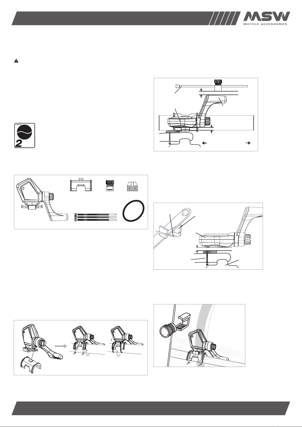
5. Use two zip ties to tighten the sensor to the chainstay, and snip off the
excess length.
6. Make any final adjustments to the sensor arm to achieve the required
distance between it and the wheel magnet, and tighten the knurled dial.
PAIRING THE MSW MINIAC DOUBLE WIRELESS
COMPUTER WITH THE SENSOR
(For pairing with other compatible cycling computers reference manufacturer’s
instructions for that computer.)
In any mode, press the M and C buttons, and hold for six seconds, and then
press C button. The computer will search for 30 seconds. If it is paired, it will
show the ID and go back to the original page in 5 seconds. If it is not paired,
check that the sensor and magnets are aligned; also check the battery (fig. 5).
Test to make sure that the magnets are activating the sensor, and the
computer head unit is registering the magnets as they pass the sensor.
MAINTENANCE
Check the position of sensor and magnet periodically. Rust or corrosion on the
magnet may cause malfunction. The gap between magnet and sensor cannot
exceed 3mm.
BATTERY REPLACEMENT
A red light on the sensor will appear when its battery is running low. Unscrew
the back cover. The (+) side should be facing up. Gently remove the battery and
replace it with a new battery model CR2032.
BATTERY WARNINGS
A coin-cell, lithium-ion battery is used in this device. If these guidelines are not
followed, batteries may experience a shortened lifespan or may present a risk
of damage to the device, fire, chemical burn, electrolyte leak, and/or injury.
• Do not leave the device exposed to a heat source or in a high-temperature
location, such as in the sun in an unattended vehicle.
To prevent the possibility of damage, remove the device from the vehicle
or store it out of direct sunlight, such as in the glove box
• Do not disassemble, modify, remanufacture, puncture or damage the device
or batteries
• Do not immerse or expose the device or batteries to water or other liquids,
fire, explosion, or other hazard
• Do not use a sharp object to remove the batteries
• Replaceable coin-cell batteries may contain perchlorate material. Special
handling may apply. See www.dtsc.ca.gov/hazardouswaste/perchlorate
• Only replace batteries with correct replacement batteries. Using other
batteries presents a risk of fire or explosion
• Do not operate the device outside of the temperature ranges specified
in these instructions
• Contact your local waste disposal department to dispose of batteries
in accordance with applicable local laws and regulations
WARNING:
• KEEP BATTERIES AWAY FROM CHILDREN
• NEVER PUT BATTERIES IN MOUTH. Swallowing can lead to chemical burns,
perforation of soft tissue, and death. Severe burns can occur within two
hours of ingestion. Seek medical attention immediately
LIMITED 2-YEAR WARRANTY
MSW warrants this new MSW product against defects in materials and
workmanship for two (2) years from the original date of retail purchase
by the consumer. This limited warranty is expressly limited to the repair
or replacement of the original product, at the option of MSW, and is the
sole remedy of the warranty. This limited warranty applies only to the
original purchaser of the MSW product and is not transferable.
In no event shall MSW be liable for any loss, inconvenience or damage,
whether direct, incidental or consequential or otherwise resulting from breach
of any express or implied warranty or condition of merchantability, fitness for
a particular purpose, or otherwise with respect to this product except as set
forth herein. This warranty gives the consumer specific legal rights, and those
rights and other rights may vary from state to state.
This warranty does not cover the following:
• Damage due to improper assembly or follow-up maintenance or lack
of skill, competence or experience of the end user
• Products that have been modified, neglected, used in competition or for
commercial purposes, misused or abused, involved in accidents or anything
other than normal use
• Damage or deterioration to the surface finish, aesthetics or appearance
of the MSW product
• Normal wear and tear
• Labor required to remove and/or refit and re-adjust the product within
the bicycle assembly
• Installation of components, parts, or accessories not originally intended
use with or compatible with MSW products
TO THE EXTENT NOT PROHIBITED BY LAW, THESE WARRANTIES ARE
EXCLUSIVE AND THERE ARE NO OTHER EXPRESS OR IMPLIED WARRANTIES
OR CONDITIONS INCLUDING WARRANTIES OR CONDITIONS OF
MERCHANTABILITY AND FITNESS FOR A PARTICULAR PURPOSE.
WARRANTY PROCESS
If you and your shop think your MSW product is worthy of a warranty
inspection, please return the product to the original place of purchase,
accompanied by a sales receipt.
For complete warranty information, visit www.mswbike.com/safety/warranty.
Bracket
Nylo n T ies
Rubber
Bracket
Cycle Computer
Rubber Pad
Bracket
Cycle Computer
1–3mm
1–3mm
Spoke
Chainstay
(non-driveside)
Rear
Wheel
Front
Wheel
Cadence Sensor Speed Sensor
Zip Tie Cadence Magnet
Crank Pedal
Cadence Sensor
1–3mm
Time Average Speed Maximum Speed Distance
Odometer Calorie Consumption
Average Cadence Maximum Cadence Trip Cadence
Unit Tire size
Time
Time
Gender / Weight ODO Temperature
Gender / Weight
M (MODE): Next option
C: Next setting
[SET]: Change the value
Temperature °C/°F
H1 (Male)
H2 (Female)
WS: 0100–2999mm
KM/H+Kg+KM
M/H+Lb+KM
12H/24H
[SET]
Weight: 20–150Kg
44–330 lb
3 seconds
Searching for 30 seconds
Press and hold mode
key for 3 seconds
After 5 seconds of receiving
code from the sensor
PAIRED NOT PAIRED
C BUTTON
MODE BUTTON
M M
C
M/CM/C
M/C
M/CM/C
M
M
M
MMM
[SET][SET]
C
M/C Save and Exit
Hour (1–24)
Minute (0–59)
Second (0–59)
>M
[SET]
C C
C
C
PRESS
Not paired:
• Check sensor alignment
• Check battery
Figure 5

Other MSW Bicycle Accessories manuals

MSW Miniac Double Wireless CC-317 User manual

MSW

MSW Miniac Double Wireless CC-317 User manual

MSW TIGER MOTH 20 USB TAILLIGHT User manual

MSW

MSW TIGER MOTH 20 USB TAILLIGHT User manual

MSW MSW-SPS-18 User manual

MSW

MSW MSW-SPS-18 User manual

MSW MINIAC CC-200 User manual

MSW

MSW MINIAC CC-200 User manual

MSW MSW-SBR-01 User manual

MSW

MSW MSW-SBR-01 User manual

MSW CRICKET SAFETY LIGHTS HLT-017 User manual

MSW

MSW CRICKET SAFETY LIGHTS HLT-017 User manual

MSW MSW-MWB-11 User manual

MSW

MSW MSW-MWB-11 User manual

MSW Ride & Repair Kit With Pump User manual

MSW

MSW Ride & Repair Kit With Pump User manual

MSW MINIAC GPS-322 User manual

MSW

MSW MINIAC GPS-322 User manual

MSW WhiteBat User manual

MSW

MSW WhiteBat User manual

MSW TIGER MOTH 40 User manual

MSW

MSW TIGER MOTH 40 User manual

MSW Clipless Pedal User manual

MSW

MSW Clipless Pedal User manual

MSW MSW-MHB-150 User manual

MSW

MSW MSW-MHB-150 User manual

MSW TOOL HUGGER KIT User manual

MSW

MSW TOOL HUGGER KIT User manual

MSW HEADSET SPACER BELL User manual

MSW

MSW HEADSET SPACER BELL User manual

MSW Miniac GPS-333 User manual

MSW

MSW Miniac GPS-333 User manual

MSW PICO User manual

MSW

MSW PICO User manual

MSW JETSTREAM INFLATOR HEAD User manual

MSW

MSW JETSTREAM INFLATOR HEAD User manual

Popular Bicycle Accessories manuals by other brands

e-bike vision 10040 Manual/Safety Notes

e-bike vision

e-bike vision 10040 Manual/Safety Notes

Cateye STRADA quick start guide

Cateye

Cateye STRADA quick start guide

Echowell a3 manual

Echowell

Echowell a3 manual

SZKTDZ KT-LCD10H user manual

SZKTDZ

SZKTDZ KT-LCD10H user manual

Thule Chariot Chinook 1 instructions

Thule

Thule Chariot Chinook 1 instructions

Tianjin Key-Disp KD59E user manual

Tianjin Key-Disp

Tianjin Key-Disp KD59E user manual

RainRider Softtop Use and Assembly Instructions

RainRider

RainRider Softtop Use and Assembly Instructions

Widek Qibbel Air manual

Widek

Widek Qibbel Air manual

BRN MY-NAVI TRACK GPS 03 user manual

BRN

BRN MY-NAVI TRACK GPS 03 user manual

HERRMANS H-BLACK MR8 EBIKE user manual

HERRMANS

HERRMANS H-BLACK MR8 EBIKE user manual

Bontrager Trip 300 manual

Bontrager

Bontrager Trip 300 manual

Shimano SL-3S35-E Service instructions

Shimano

Shimano SL-3S35-E Service instructions

toboli 63115 operating manual

toboli

toboli 63115 operating manual

Shimano Nexus Inter-8 Dealer's manual

Shimano

Shimano Nexus Inter-8 Dealer's manual

Sigma ROX 12.0 SPORT user guide

Sigma

Sigma ROX 12.0 SPORT user guide

Xtracycle Porterrack manual

Xtracycle

Xtracycle Porterrack manual

Efneo GTRO manual

Efneo

Efneo GTRO manual

Polini Hi-Speed manual

Polini

Polini Hi-Speed manual

manuals.online logo
manuals.online logoBrands
  • About & Mission
  • Contact us
  • Privacy Policy
  • Terms and Conditions

Copyright 2025 Manuals.Online. All Rights Reserved.