manuals.online logo
Brands
  1. Home
  2. •
  3. Brands
  4. •
  5. MSW
  6. •
  7. Bicycle Accessories
  8. •
  9. MSW HEADSET SPACER BELL User manual

MSW HEADSET SPACER BELL User manual

49388 11/18 | 85-001044_INST_A
HEADSET SPACER BELL INSTRUCTIONS
6400 WEST 105TH STREET // BLOOMINGTON, MN 55438 // 1-855-883-6563 // WWW.MSWBIKE.COM
Thank you for your purchase! At MSW®we believe having essential
accessories makes a good bike ride great. The MSW Headset Spacer Bell fits
seamlessly into your headset stack, leaving your handlebars free for other
accessories.
WARNING: Cycling can be dangerous. Bicycle products should be installed
and serviced by a professional mechanic. Never modify your bicycle or
accessories. Read and follow all product instructions and warnings including
information on the manufacturer’s website. Inspect your bicycle before every
ride. Always wear a helmet.
For additional product and safety information go to: www.mswbike.com/safety.
INTENDED USE
The MSW Bell is designed to replace one or more spacers between
the bicycle headset and stem. The three-step installation
procedure requires the removal and replacement of the stem cap,
stem and handlebars. If you’re not familar with the procedures
shown here, obtain help from a qualified bicycle mechanic.
TOOLS AND SUPPLIES
You will need:
• Headset spacers (if needed)
• 4, 5, 6mm hex-bit sockets
• Torque wrench with Newton-meter scale
INSTALLATION INTRODUCTION
The MSW Bell is designed to replace one or more spacers between the bicycle
headset and stem. The three-step installation procedure requires the removal
and replacement of the stem cap, stem and handlebars. If you’re not familar with
the procedures shown here, obtain help from a qualified bicycle mechanic.
WARNING: The spacing between the top of the steerer tube and the stem
is critical. Failure to maintain the spacing shown below can result in stem/
handlebar separation, crash and serious injury.
INSTALLATION STEPS
1. Remove stem cap and stem
2. Swap bell mounting ring in place of existing spacer(s) and reassemble
3. Confirm steerer tube to stem spacing and torque stem cap to specification
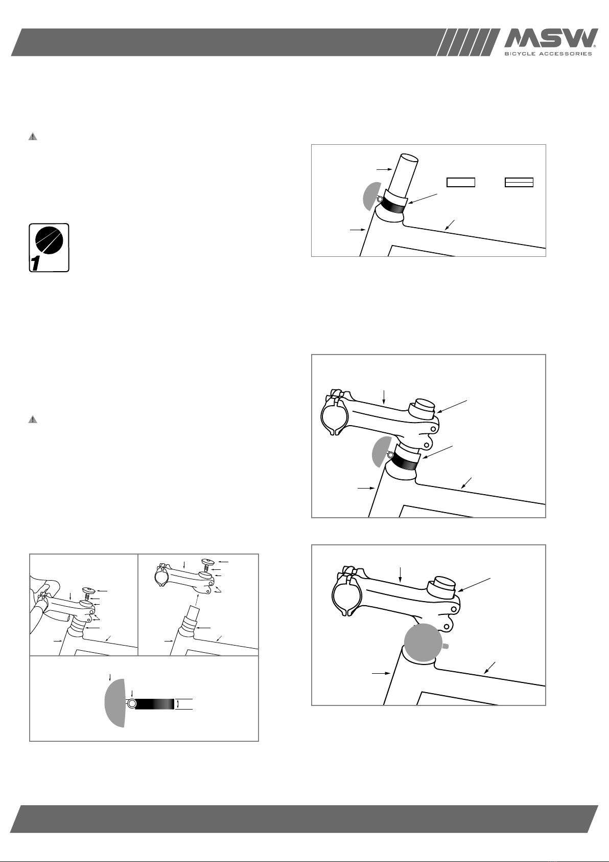
STEP 1: REMOVE STEM CAP & STEM
Remove stem bolt and cap and top spacer. Loosen stem bolts and remove
stem and handlebars (Fig 1).
STEP 2: SWAP BELL IN PLACE OF
SPACER(S) AND REASSEMBLE
Remove one 10mm spacer or two 5mm spacers and install bell in place of the
removed spacer(s) (Fig 2).
Slide the existing spacer(s), stem and top spacer onto steerer tube (Fig. 3).
Rotate bell gong to preferred position on left or right side of steerer tube
(Fig. 4). Do not install step bolt and cap at this point.
Figure 1
Headtube
Frame
Spacer stack
Stem clamp bolts
10mm spacer
Stem cap
Stem
Stem cap bolt
Stem
Headtube
Frame
Spacer stack
Remove
Stem clamp bolts
10mm spacer
Stem cap
Stem cap bolt
Stem
Gong
Clapper
10mm
Bell Mounting Ring
Figure 1
Figure 3
Headtube
Frame
10mm Spacer 2-5mm Spacers
Existing spacer
Top spacer
Figure 2
Headtube
Frame
Steerer tube
or
Figure 2
Headtube
Frame
Spacer stack
Stem clamp bolts
10mm spacer
Stem cap
Stem
Stem cap bolt
Stem
Headtube
Frame
Spacer stack
Remove
Stem clamp bolts
10mm spacer
Stem cap
Stem cap bolt
Stem
Gong
Clapper
10mm
Bell Mounting Ring
Figure 1
Figure 3
Headtube
Frame
10mm Spacer 2-5mm Spacers
Existing spacer
Top spacer
Figure 2
Headtube
Frame
Steerer tube
or
Figure 3
Headtube
Frame
Spacer stack
Stem clamp bolts
10mm spacer
Stem cap
Stem
Stem cap bolt
Stem
Headtube
Frame
Spacer stack
Remove
Stem clamp bolts
10mm spacer
Stem cap
Stem cap bolt
Stem
Gong
Clapper
10mm
Bell Mounting Ring
Figure 1
Figure 3
Headtube
Frame
10mm Spacer 2-5mm Spacers
Existing spacer
Top spacer
Figure 2
Headtube
Frame
Steerer tube
or
Figure 4
3mm
Stem
Figure 4
Headtube
Frame
Top spacer
Stem
Figure 5
Figure 6
Top of spacer
Top of steerer tube
For riding on a
paved surface where
the tires do not lose
ground contact
ASTM F2043
49388 11/18 | 85-001044_INST_A
HEADSET SPACER BELL INSTRUCTIONS
6400 WEST 105TH STREET // BLOOMINGTON, MN 55438 // 1-855-883-6563 // WWW.MSWBIKE.COM
STEP 3: CONFIRM STEERER TUBE-TO-
STEM SPACING AND TORQUE STEM CAP
TO SPECIFICATION
After reassembly, confirm that the steerer is 3mm below the top spacer (Fig. 5).
Add or remove spacers below the stem if required to achieve the 3mm gap.
Install stem cap and bolt and torque to manufacturer’s specification.
Adjust clapper position by loosening the gong slightly and rotating the clapper
to the desired position. Tighten gong while holding the clapper in place (Fig. 6).
WARRANTY PROCESS
If you and your shop think your MSW product is worthy of a warranty
inspection, please return the product to the original place of purchase,
accompanied by a sales receipt.
For complete warranty information, visit www.mswbike.com/safety/warranty.
Figure 5
3mm
Stem
Figure 4
Headtube
Frame
Top spacer
Stem
Figure 5
Figure 6
Top of spacer
Top of steerer tube
Figure 6
3mm
Stem
Figure 4
Headtube
Frame
Top spacer
Stem
Figure 5
Figure 6
Top of spacer
Top of steerer tube

Other MSW Bicycle Accessories manuals

MSW Clipless Pedal User manual

MSW

MSW Clipless Pedal User manual

MSW TIGER MOTH 40 User manual

MSW

MSW TIGER MOTH 40 User manual

MSW MSW-MHB-150 User manual

MSW

MSW MSW-MHB-150 User manual

MSW TIGER MOTH 20 USB TAILLIGHT User manual

MSW

MSW TIGER MOTH 20 USB TAILLIGHT User manual

MSW Ride & Repair Kit With Pump User manual

MSW

MSW Ride & Repair Kit With Pump User manual

MSW JETSTREAM INFLATOR HEAD User manual

MSW

MSW JETSTREAM INFLATOR HEAD User manual

MSW Miniac GPS-333 User manual

MSW

MSW Miniac GPS-333 User manual

MSW MSW-MWB-11 User manual

MSW

MSW MSW-MWB-11 User manual

MSW TOOL HUGGER KIT User manual

MSW

MSW TOOL HUGGER KIT User manual

MSW MSW-SBR-01 User manual

MSW

MSW MSW-SBR-01 User manual

MSW MINIAC CC-200 User manual

MSW

MSW MINIAC CC-200 User manual

MSW MINIAC User manual

MSW

MSW MINIAC User manual

MSW PICO User manual

MSW

MSW PICO User manual

MSW WhiteBat User manual

MSW

MSW WhiteBat User manual

MSW CRICKET SAFETY LIGHTS HLT-017 User manual

MSW

MSW CRICKET SAFETY LIGHTS HLT-017 User manual

MSW MINIAC GPS-322 User manual

MSW

MSW MINIAC GPS-322 User manual

MSW MSW-SPS-18 User manual

MSW

MSW MSW-SPS-18 User manual

MSW Miniac Double Wireless CC-317 User manual

MSW

MSW Miniac Double Wireless CC-317 User manual

Popular Bicycle Accessories manuals by other brands

WHEELSWING VOLT 1 user manual

WHEELSWING

WHEELSWING VOLT 1 user manual

Look KEO BLADE manual

Look

Look KEO BLADE manual

VDO X2DW instruction manual

VDO

VDO X2DW instruction manual

Bikespeed RealSpeed Instruction for the installation

Bikespeed

Bikespeed RealSpeed Instruction for the installation

Cateye CC-HB100 owner's manual

Cateye

Cateye CC-HB100 owner's manual

CarryBright CBRCTL01 user manual

CarryBright

CarryBright CBRCTL01 user manual

Fiamma Mercedes Viano installation instructions

Fiamma

Fiamma Mercedes Viano installation instructions

Schwinn Mark II operating instructions

Schwinn

Schwinn Mark II operating instructions

EUFAB 132027 manual

EUFAB

EUFAB 132027 manual

Burley ENCORE installation instructions

Burley

Burley ENCORE installation instructions

EUFAB 11232 manual

EUFAB

EUFAB 11232 manual

Knog NERD 9 manual

Knog

Knog NERD 9 manual

FOVNO ES-H1B instructions

FOVNO

FOVNO ES-H1B instructions

Bell Dashboard 300 manual

Bell

Bell Dashboard 300 manual

Ortlieb QUICK RACK Assembly instructions

Ortlieb

Ortlieb QUICK RACK Assembly instructions

Planet Bike 7033 installation manual

Planet Bike

Planet Bike 7033 installation manual

Bryton Rider 20+ user manual

Bryton

Bryton Rider 20+ user manual

Manitou JACK DROPPER POST Setup guide

Manitou

Manitou JACK DROPPER POST Setup guide

manuals.online logo
manuals.online logoBrands
  • About & Mission
  • Contact us
  • Privacy Policy
  • Terms and Conditions

Copyright 2025 Manuals.Online. All Rights Reserved.