MTD 190-751-OEM User manual

OPERATOR’S MANUAL
TRACTOR SNOW CAB
Model Number
190-751-OEM
PRINTED IN U.S.A. FORM NO. 48898 (7/03)
MTD PRODUCTS INC. P.O. BOX 368022 CLEVELAND, OHIO 44136-9722
IMPORTANT: READ SAFETY RULES AND INSTRUCTION CAREFULLY.

2
Any powe equipment can cause inju y if ope ated imp ope ly o if the use does not unde stand how to ope ate
the equipment. Exe cise caution at all times, when using powe equipment.
1. This cab p ovides foul weathe p otection only. It
does not p ovide p otection against exhaust fumes,
collision, ollove o othe accidents.
2. Read the snow cab and vehicle owne 's manuals
and know how to ope ate you vehicle befo e using
the snow cab attachment.
3. Be su e the e is adequate ventilation when using
the t acto and snow cab in confined a eas.
4. The snow cab will est ict you field of vision in
some di ections. Use ext a caution when ope ating
you t acto with the snow cab attached.
5. Watch out fo low t ee limbs o othe ove head
obst uctions that may not p eviously have inte -
fe ed with ope ation of the t acto . The ext a height
of the snow cab may cause these objects to
become obstacles.
6. Check the a ea of ope ation tho oughly befo e
using the t acto .
Look fo this symbol to point out impo tant safety p ecautions. It means--Attention!!
Become alert!! Your safety is involved.
RULES FOR SAFE OPERATION
UNPACKING
NTENTS
Open ca ton. Remove pa ts and lite atu e. Make
ce tain all pa ts and lite atu e a e emoved befo e
the ca ton is disca ded.
Lay out all pa ts acco ding to the illust ation below.
CARTON CONTENTS
7. Up ight Tubes (2)
8. Rope
9. Suppo t Rods (3)
10. Top Tubes (2)
11. Vinyl Canopy
Pa ts Bag (see page 3)
1. Base Assembly
2. RH Adapte B acket
3. LH Adapte B acket
4. Tool B acket
5. D awba B acket
6. U-Tube
7
610
9
8
5
2
3
11
4
1

3
REF. QTY. DESCRIPTION REF. QTY. DESCRIPTION
A 1 Hex Bolt, 5/8” x 1-3/4”
B 2 Ca iage Bolt, 5/16 x 2"
C 4 Hex Bolt, 1/4 x 1-1/2"
D 8 Hex Bolt, 5/16” x 1”
E 2 Shoulde Bolt
F 8 Lock Washe , 5/16”
G 2 Flat Washe , 5/16”
H 4 Hex Lock Nut, 1/4”
I 8 Hex Nut, 5/16”
J 1 Hex Nut, 5/8”
K 2 Jam Nut, 1/2”
L 4 Spi al Hook
M 2 Foot est Clamp
N 2 Plastic Knob
ABCD E
FG
LMN
HJKI
NOT SHOWN FULL SIZE
SHOWN FULL SIZE

4
TOOLS REQUIRED FOR ASSEMBLY
(2) 7/16" W enches
(2) 1/2” W enches
(1) 3/4” W ench
(2) 15/16” W enches
REMOVAL OF PARTS FROM TRACTOR
1. Remove any ea mounted attachments which
may be installed on you t acto
2. Ma k and save all emoved pa ts.
ASSEMBLING BRACKETS TO TRACTOR
FAST-ATTACH TRACTORS
3. Skip to ASSEMBLING THE BASE
STANDARD FRAME TRACTORS
4. Remove top fou bolts f om ea of t acto f ame.
See figu e 1.
5. Attach LH and RH adapte b ackets to ea of t acto
f ame using bolts emoved in step 4. See figu e 2.
FIGURE 1
FIGURE 3
FIGURE 2
ASSEMBLING THE BASE
7. Assemble the d awba b acket to the base
assembly using fou 5/16” x 1” hex bolts, 5/16”
lockwashe s and 5/16” hex nuts. See figu e 3.
8. Attach the tool b acket to the base assembly
using fou 5/16” x 1” hex bolts, 5/16”
lockwashe s and 5/16” hex nuts. See figu e 3.
6. Assemble a shoulde bolt and a 1/2” jam nut to each
adapte b acket. See figu e 2.
ATTACHING BASE TO TRACTOR
FAST ATTACH TRACTORS
9. Hook the base assembly unde the shoulde bolts on
the sides the t acto f ame using the front notches in
the base assembly. Align the hole in the bottom of
the base assembly with the hole in the t acto d aw-
ba . Inse t the 5/8” x 1-3/4” hex bolt and secu e it with
the 5/8” hex nut. See figu e 4.
FIGURE 4
BOLTS FROM
TRACTOR FRAME
L.H. ADAPTER
BRACKET
R.H. ADAPTER
BRACKET
SHOULDER
BOLT
1/2" JAM NUT
1/2" JAM NUT
SHOULDER
BOLT
5/16" x 1"
HEX BOLT
5/16" HEX NUT
5/16" LOCK WASHER
DRAWBAR
BRACKET
TOOL BRACKET
BASE
ASSEMBLY
5/8" HEX NUT
5/8" x 1-3/4"
HEX BOLT
SHOULDER BOLT

5
12. Assemble the top tubes to the up ight tubes using two
1/4" x 1-1/2" hex bolts (f om outside) and two 1/4" hex
lock nuts (inside). Do not tighten yet. See figu e 7.
13. Fit the f ont U-tube onto the top tubes. Fasten the
tubes togethe using two 1/4" x 1-1/2" hex bolts (on
outside) and two 1/4" hex lock nuts (on inside).
Tighten all loose bolts. See figu e 7.
14. Fit the th ee suppo t ods into the holes in the top
tubes, with the ods a ching upwa d. Do not ove
bend the ods when installing. See figu e 7.
STANDARD FRAME TRACTORS
10. Hook the base assembly unde the shoulde bolts in
the adapte b ackets using the second notch in the
base assembly. Align the hole in the bottom of the
base assembly with the hole in the t acto d awba .
Inse t the 5/8” x 1-3/4” hex bolt and secu e it with the
5/8” hex nut. See figu e 5.
FIGURE 5
FIGURE 6
FIGURE 7
15. Install a foot est clamp with p eassembled bolt onto
the f ont edge of each foot est, with the bolt unde -
neath the foot est. See figu e 8.
16. Raise the t acto 's hood. Place the snow cab canopy
onto the tubing f ame, d aping the f ont flap down in
f ont of the t acto 's dash panel. Lowe the hood,
t apping the f ont flap unde the hood. Secu e the
sides of the canopy by fastening the elastic hooks to
the bottom edge of the foot est and fende . Leve s o
handles on snowth owe s and snow blades should be
located outside of the cab. See figu e 8.
FIGURE 8
ASSEMBLING THE FRAME
11. Assemble the up ight tubes to the base assembly
using two 5/16-18 x 2" ca iage bolts (f om outside)
and two 5/16" flat washe s and plastic knobs (f om
inside). See figu e 6.
5/8" HEX NUT
5/8" x 1-3/4"
HEX BOLT
SHOULDER BOLT
5/16" x 2"
CARRIAGE
BOLT
5/16" FLAT
WASHER
PLASTIC
KNOB
1/4" HEX
LOCK NUT
1/4" x 1-1/2"
HEX BOLT SUPPORT ROD
1/4" x 1-1/2"
HEX BOLT
1/4" HEX
LOCK NUT
ELASTIC HOOKS
FRONT FLAP
RAISE HOOD
FOOTREST CLAMP

6
1. Check the a ea of ope ation tho oughly befo e
using the t acto with the snow cab. The added
height of the snow cab and a educed field of vision
equi e ext a caution du ing ope ation.
2. Ente the snow cab on the left side at the ea .
Unfasten the elastic hook at the bottom and the
velc o fastene in the top in the ea co ne .
3. Ope ate outside cont ols on a snowth owe o snow
blade th ough the access flaps in the sides of the
canopy.
4. Remove the uppe snow cab f ame and canopy
befo e you t anspo t the t acto in an open t uck o
open t aile .
CAUTION: Watch out fo low t ee
limbs and othe ove head objects which
may inte fe e with the snow cab.
CAUTION: Never t anspo t the t acto in
an open t uck o open t aile while the
snow cab is attached.
CAUTION: This cab p ovides foul
weathe p otection only. It does not
p ovide p otection against exhaust fumes,
collision, ollove o othe accidents.
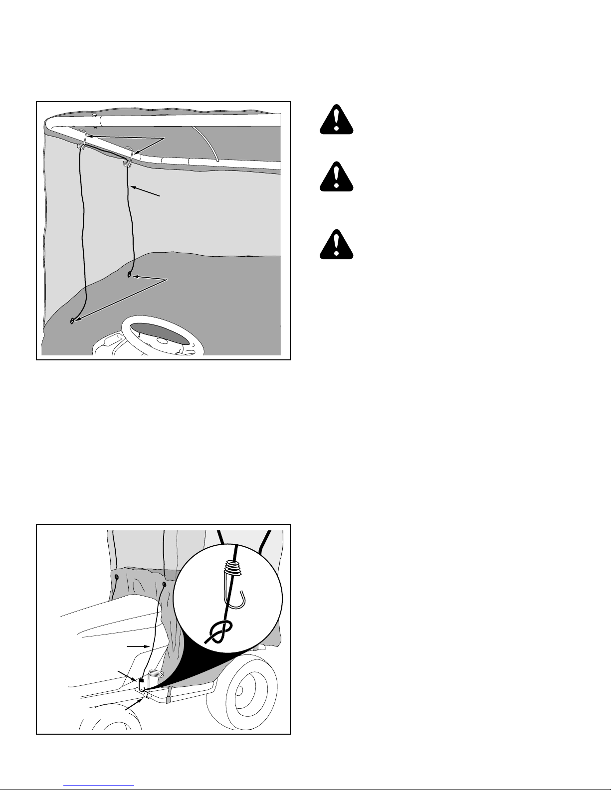
17. Assemble two spi al hooks into holes on top of u-tube
at f ont of tubing f ame. See figu e 9.
18. Inse t ends of ope down th ough spi al hooks
attached to u-tube and then inse t ends th ough two
g ommets in f ont of canopy. See figu e 9.
FIGURE 9
19. Inse t one end of ope th ough a thi d spi al hook and
tie a knot in end of ope. See figu e 10.
20. Assemble spi al hook with ope attached th ough
hole in foot est clamp. See figu e 10.
21. Inse t othe end of ope th ough emaining spi al
hook. Tie a knot in end of ope so that when hooked
to othe foot est clamp the ope is tight and canopy
f ame is stable. See figu e 10.
FIGURE 10
OPERATING THE SNOW CAB
Read this owner's manual and safety rules before
operating your tractor with the Snow Cab.
MAINTENANCE
1. Befo e each use make a tho ough visual check of
the snow cab fo any bolts and nuts which may
have loosened. Retighten any loose bolts and nuts.
2. The vinyl po tion of the canopy can be washed
using wate only, o a mild liquid soap and wate .
3. The plastic windows should only be washed using
unning wate , o a mild liquid soap and wate .
Wash the windows with you ba e hands only. A
cloth, sponge o b ush will sc atch the clea plastic.
IMPORTANT: Neve clean the windows when the
plastic is d y. The clea plastic will sc atch.
4. Clean the vinyl canopy tho oughly and allow to d y
befo e sto ing. Refe to the Cleaning section.
5 . Sto e the snow cab in a clean, d y a ea away f om
di ect sun light.
ROPE
SPIRAL HOOKSSPIRAL HOOKS
GROMMETSGROMMETS
ROPE
FOOTREST CLAMP
SPIRAL HOOK

7
REF. PART QTY. DESCRIPTION
NO. NO.
1 64717 1 Base Assembly
2 25014 2 Up ight Tube
3 25013 2 Top Tube
4 25012 1 U-Tube
5 25015 3 Suppo t Rod
6 48895 1 Vinyl Canopy
7 25141 1 D awba B acket
8 43720 2 Plastic Knob
9 44977 2 Ca iage Bolt, 5/16-18 x 2"
10 43081 2 Flat Washe , 5/16"
11 43648 4 Hex Bolt, 1/4-20 x 1-1/2"
12 43013 4 Hex Lock Nut, 1/4-20
13 25190 1 Adapte B acket, RH
14 25189 1 Adapte B acket, LH
REF. PART QTY. DESCRIPTION
NO. NO.
15 25140 1 Tool B acket
16 49017 1 Rope
17 49016 4 Spi al Hook
18 64802 2 Foot est Clamp
19 43083 8 Hex, Nut 5/16-18
20 43086 8 Lock Washe , 5/16”
21 43063 8 Hex Bolt, 5/16-18 x 1”
22 47951 1 Hex Bolt, 5/8-11 x 1-3/4”
23 712-0261 1 Hex Nut, 5/8-11 Nylock
24 738-0816 2 Shoulde Bolt
25 48115 2 Hex Nut, 1/2-13 Jam Nylock
26 46703 2 Hex Bolt, 5/16-18 x 3/4” Self Thd.
48898 1 Owne 's Manual
REPAIR PARTS FOR MODEL 190-751-OEM TRACTOR SNOW CAB
1
2
2
4
3
35
7
19
23
20
19
20
21
22
21
9
10
11
12
8
13
14
24
25 15
6
16
17 17
17
17
18
26
18
26

1-800-800-7310
If you are having difficulty assembling this product or if you have any
question regarding the controls, operation or maintenance of this unit,
please call the Customer Support Department. You can reach them by
calling:
Table of contents
Other MTD Tractor Accessories manuals

MTD
MTD 19A30003OEM User manual

MTD
MTD 400 Series User manual

MTD
MTD 19A30020OEM User manual

MTD
MTD 19A70041OEM User manual

MTD
MTD 19A30020OEM User manual

MTD
MTD 490-900-0024 User manual

MTD
MTD 190-751-OEM User manual

MTD
MTD Pro Z Series User manual

MTD
MTD 19A70054 Series User manual

MTD
MTD 490-241-B032 User manual