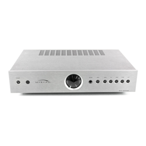
Myryad Z162 User manual

Z-SERIES
Z162PowerAmplifier
Owner’s manual
This symbol means do not dispose of as municpal waste.
Re-use or recycle wherever possible. Electrical/Electronic
Equipment may contain substances harmful to the
environment. For environmentally sound methods of disposal,
please contact your local government agency.
Revision: 1
www.myryad.co.uk
Stortford Hall Industrial Park, Dunmow Road
Bishops Stortford, Hertfordshire, CM23 5GZ
www.armourhome.co.uk


3
CONTENTS
• Introduction 3
• Installation and Safety 3
• Accessories 3
• Setting up your Amplifier
Rear panel connections 4
• Operating your Amplifier
Front panel controls 5
• Loudspeaker Output Protection and Muting 5
• Bi-Amp Wiring 6
• Trouble-shooting guide 6
• Specifications 6
INTRODUCTION
The Myryad Z162 Power Amplifier has been designed to offer a
combination of high quality sound reproduction and elegant
styling.
The Z162 can be used to provide power for high quality stereo
systems when partnered by a suitable preamplifier or, in
partnership with a Z142 Integrated Amplifier, to provide a very
high performance four channel solution for bi-amp capable
loudspeakers. Multiple Z162 amplifiers can also be used to power
a full-surround music or Home Cinema sound system of the
highest quality.
The Z162 has a pair of unbalanced line inputs plus directly linked
line outputs, all on RCA phono sockets.
The Z162 is Smart My-Link® compatible. When it is connected
via the Smart My-Link® to a Myryad Z or MX Series integrated
amplifier (such as the matching Z142) or preamplifier, the Z162
will be switched on/off whenever the integrated/preamp is
switched on or off – whether from the front panel, remote control
or via the Smart My-Link® bus.
INSTALLATION AND SAFETY
The Z162 generates a modest amount of heat and requires
ventilation. Do not place it on a rug or other soft surface into
which it could sink, obstructing the air inlets in its underside. Do
not allow any obstruction to the ventilation slots in the top cover. If
a number of Z-Series units are stacked on top of one another, the
Z162 should be placed at or near the top. The Z162 should not be
installed in a built-in situation such as a bookcase or rack unless
proper ventilation is provided.
CAUTION: THIS APPARATUS MUST NOT BE EXPOSED TO
DRIPPING OR SPLASHING. OBJECTS FILLED WITH LIQUIDS
SUCH AS VASES MUST NOT BE PLACED ON THE
APPARATUS.
THE REAR PANEL POWER SWITCH DISCONNECTS MAINS
LIVE ONLY. THE POWER CORD MUST BE DISCONNECTED
FROM THE REAR OF THE APPARATUS, OR THE WALL
SOCKET, TO PROVIDE TOTAL ISOLATION. ONE OR OTHER
OF THESE CONNECTIONS MUST BE READILY ACCESSIBLE
WHEN THE APPARATUS IS IN USE.
Do not remove the cover, or attempt to modify or repair any item
yourself. Refer all servicing to a qualified technician.
ACCESSORIES
Your Z162 is supplied with the following accessories.
• Separate mains power cord to suit country of sale.
• My-Link interconnect (0.5m RCA-RCA).

4
SETTING UP YOUR AMPLIFIER
REAR PANEL CONNECTIONS
1 Power inlet
Before making any connection, check that the mains voltage
setting printed on the rear panel is the same as your local mains
supply. Plug the female (socket) end of the power cord into the
power inlet on the rear of the amplifier. Plug the male (plug) end
of the cord into a “live” wall socket or a suitable heavy duty
extension cable.
2 Power switch
Press one side of this rocker switch (the side nearer the edge of
the rear panel) to switch the amplifier ON and the other side to
switch it OFF. When the POWER switch is in the OFF position all
power is disconnected from the amplifier and it cannot be
powered up from the front panel or the remote control. When the
POWER switch is in the ON position (and the power cord
correctly inserted and plugged in to a live wall socket) the
amplifier will power up in standby mode (see FRONT PANEL
CONTROLS, STANDBY, page 5). It is recommended that the
POWER switch is turned OFF if the amplifier is not going to be
used for an extended period of time.
3 My-Link input/output
When the Z162 is used in a system with other Z-Series products
(or Myryad MX-Series), all may be joined together via the My-Link.
My-Link is a communications bus that allows all the linked
components to operate together as a system and distributes the
remote commands received by any one to each of the others.
Connection to the My-Link bus means that the Z162 and all other
linked units will switch into or out of standby mode when the front
panel or remote control standby key of the controlling integrated
amplifier (or preamplifier) is pressed.
Use a short RCA-to-RCA (phono-to-phono) interconnect cable to
connect from the MY-LINK IN socket on the Z162 to the MY-LINK
OUT socket on the integrated amplifier. A second cable may then
be run from the MY-LINK OUT socket on Z162 to the MY-LINK IN
socket on a Myryad CD player (for example) – “daisy-chain”
fashion. Further compatible Myryad products can be linked in the
same way, running from the MY-LINK OUT socket on the CD
player. Inexpensive interconnects may be used as the My-Link
bus carries only control signals, not audio, so these cables have
no effect on sound quality.
4 Loudspeaker outputs
The loudspeaker outputs are capable of driving all loudspeakers
with rated impedances in the range 4Ωto 16Ω. The loudspeaker
terminals are high–current binding–posts, coded red or black. The
terminals on the left side of the amplifier (viewed from the front)
and marked “LEFT” should be wired to the left-hand loudspeaker.
Those on the right, marked “RIGHT”, should be wired to the right-
hand loudspeaker.
For correct stereo imaging it is important that the two
loudspeakers are wired “in phase”. To ensure correct phasing
wire the black (–) terminal on the amplifier to the black or “–”
terminal on the loudspeaker. The red (+) terminal on the amplifier
should be wired to the red or “+” terminal on the loudspeaker.
The loudspeakers should be positioned as recommended by the
loudspeaker manufacturer. The two loudspeakers should always
be placed at equal distances from the main listening position and
usually spaced a similar distance apart. It is generally best to
keep the loudspeakers away from room corners and many
loudspeakers work best away from all walls.
5 Line input
The line inputs may be connected to the line outputs of any
quality preamplifier, or to the bi-amp outputs of an integrated
amplifier such as the Myryad Z142 (see page 6).
6 Line output
The line outputs are directly connected to the line inputs, without
buffering. The line outputs allow further power amps to be “daisy-
chained” so more complex systems may be built.
1
STANDBY
5
OPERATING YOUR AMPLIFIER
FRONT PANEL CONTROLS
1 Standby
When the amplifier is plugged into a live wall socket and the
POWER switch is turned ON, it will power up in “standby” mode
and the LED (Light Emitting Diode) by the STANDBY button will
glow red. In this mode the internal circuitry is powered up, but
disabled so that it consumes very little power and the loudspeaker
outputs are muted by a relay.
When the STANDBY button is pressed the circuitry is activated
and, after a few seconds delay, the loudspeaker outputs will be
enabled. During this delay period while the internal circuitry is
settling the STANDBY LED will flash blue. When the outputs are
de-muted it will glow blue continuously. When the STANDBY
button is pressed again the amplifier will be returned to standby
mode, the STANDBY LED will glow red again and all other LEDs
and displays will be extinguished.
CAUTION: WHEN IN STANDBY MODE THE INTERNAL
CIRCUITRY IS STILL LIVE, SO ALL SAFETY PRECAUTIONS
MUST BE FOLLOWED.
LOUDSPEAKER OUTPUT
PROTECTION AND MUTING
When the amplifier is in standby mode the loudspeaker output
terminals are isolated from the amplifier by a high quality relay.
When the amplifier is first switched on from standby mode the
loudspeaker outputs remain disconnected for a few seconds to
allow the internal voltage levels to settle. The same process
occurs when the amplifier is switched back into standby mode.
The same loudspeaker mute relay is used to protect both the
amplifier and your loudspeakers against possible damage. If any
one of a number of fault modes is detected (loudspeaker outputs
short circuit, amplifier overheating, amplifier DC fault) the
loudspeakers will be disconnected from the amplifier to protect
both. In the case of a short circuit or DC fault the loudspeakers
will be re-connected after a few seconds, but will be disconnected
again if the fault persists. If overheating has caused the protection
system to operate, then it will take some time for the heatsinks to
cool sufficiently to allow the loudspeakers to be re-connected
(probably between five and fifteen minutes depending upon the
room temperature and ventilation). The amplifier will cool more
quickly if it is switched to standby mode, or if the POWER is
switched OFF.

6
BI-AMP WIRING
Many loudspeakers today are made so that the bass and treble
sections can be separated and fed from two sets of speaker
cables. This is known as “bi-wiring” and can yield a significant
improvement in sound quality.
A further sound quality gain may be made by “bi-amplifying” the
loudspeaker – using two separate power amplifiers to drive the
bass and treble sections. The Z162 can be used together with its
matching integrated amplifier the Z142 for this purpose.
The Z142’s “BI-AMP” output can be used to feed the line input on
the Z162. The Z142’s loudspeaker outputs are be connected to
the bass sections of the loudspeakers (left and right) while the
Z162 drives the treble. The diagram below illustrates this setup.
TROUBLE-SHOOTING GUIDE
Possible solutions to some of the most common problems.
No sound:
• Power turned off or system in standby mode. Check that the
blue STANDBY LED in the amplifier is illuminated and that the
source integrated or preamp is also active.
• Input connections loose or missing. Check that all connections
are secure.
• Protection relay has operated because of a short circuit
loudspeaker wire or amplifier overheating. Carefully check all
wiring after switching the amplifier POWER OFF to allow it to cool.
• UK version only: The fuse in the mains plug has failed. Check
and replace if necessary.
Sound in one channel only:
• Loudspeaker cable pulled loose. Check all connections, both at
the loudspeakers and amplifier.
• Interconnect cable pulled loose or making poor contact. Check
and, if necessary, un-plug and re-plug all relevant cables.
Loud buzz or hum:
• Interconnect cable pulled partially out of its socket.
• Defective interconnect cable.
For further help please visit the Myryad website at
www.myryad.co.uk
SPECIFICATIONS
Continuous rated power output, 8?(<0.1% THD) 50W
Signal/noise ratio (A-weighted, ref 50W) 110dB
Input sensitivity (ref 50W) 700mV
Frequency response (20Hz – 20kHz) ±0.3dB
Dimensions (w x h x d) 436 x 78 x 316mm
Weight (net) 6.7kg
Supply voltage (set by internal wiring) 120 or 230V
Finish Natural Silver fascia with Silver Grey casing or Satin Black fascia with Black Casing.
Connect Z142 SPEAKERS outputs to loudspeaker “Bass” or “LF”
terminals and Z162 SPEAKERS outputs to loudspeaker “Treble”
or “HF” terminals. Take care to observe LEFT and RIGHT.
Connect Z142 BI-AMP OUTPUT to Z162 LINE INPUT.
HF
LF
HF
LF
R
RL
L
Bi-amp Output
to
Line Level Input


Z-SERIES
Z162PowerAmplifier
Owner’s manual
This symbol means do not dispose of as municpal waste.
Re-use or recycle wherever possible. Electrical/Electronic
Equipment may contain substances harmful to the
environment. For environmentally sound methods of disposal,
please contact your local government agency.
Revision: 1
www.myryad.co.uk
Stortford Hall Industrial Park, Dunmow Road
Bishops Stortford, Hertfordshire, CM23 5GZ
www.armourhome.co.uk
Table of contents
Other Myryad Amplifier manuals

Myryad
Myryad MA120 User manual

Myryad
Myryad Z140 User manual

Myryad
Myryad Z Series User manual

Myryad
Myryad mi 120 User manual

Myryad
Myryad MP100 User manual

Myryad
Myryad MA500 User manual

Myryad
Myryad MI 240 User manual

Myryad
Myryad MXA2080 User manual

Myryad
Myryad ZMINI Z40 User manual

Myryad
Myryad MDP 500 G6 User manual