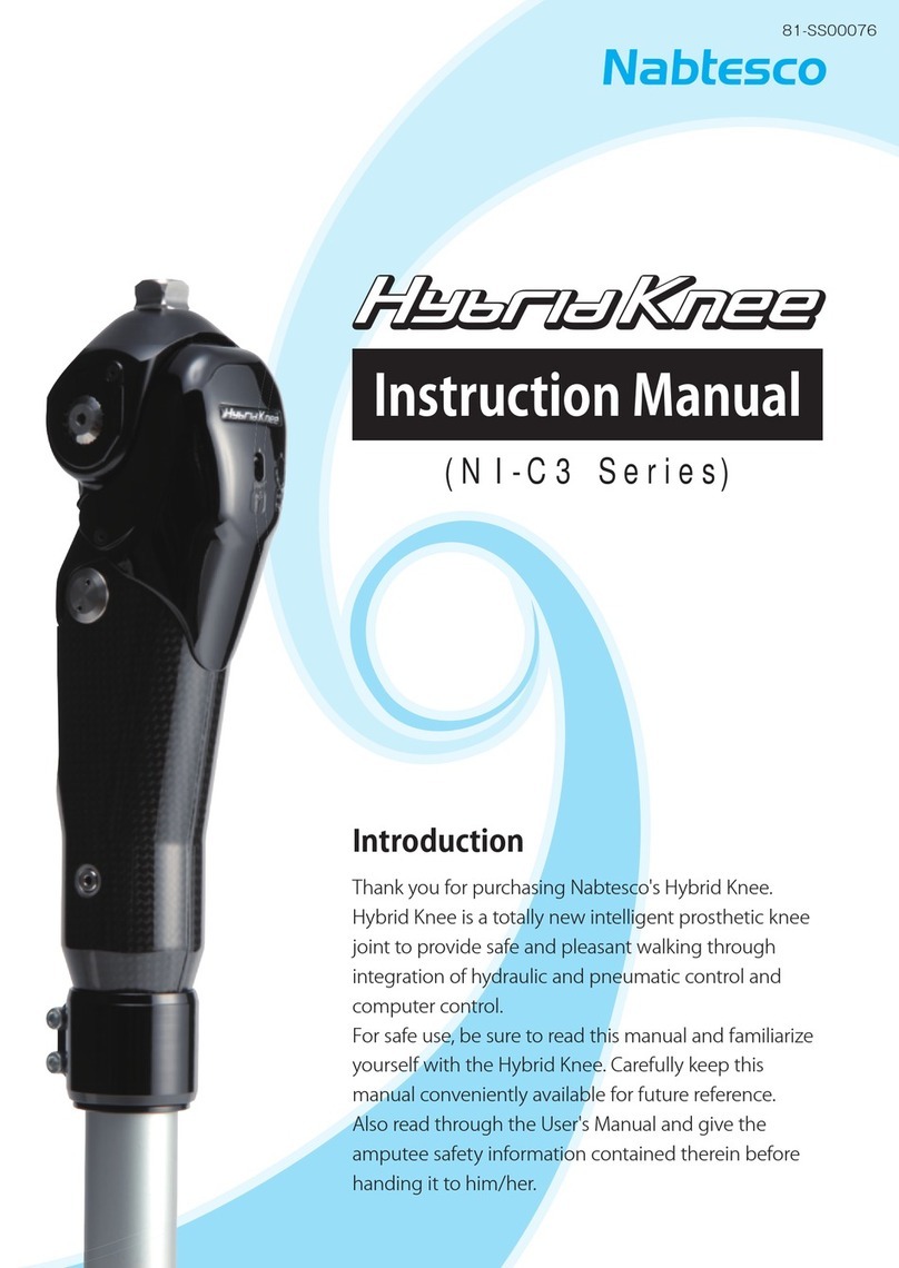
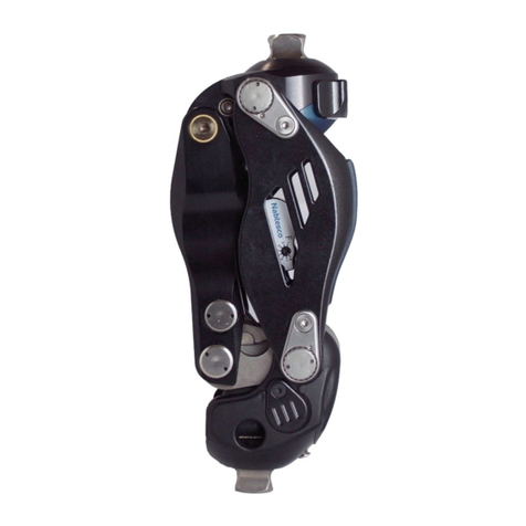
Nabtesco HybridKnee NI-C3 Series User manual

Introduction
Thank you for purchasing Nabtesco's Hybrid Knee.
Hybrid Knee is a totally new intelligent prosthetic knee joint
that integrates hydraulic and pneumatic control with com-
puter control to provide safe and pleasant walking.
For safe use, be sure to read this manual and familiarize
yourself with the Hybrid Knee. Carefully keep this manual
conveniently available for future reference.
Also read through the User's Guide and explain the safety
information contained therein to the patient before hand-
ing the User's Guide to him/her.
(Nl-C3 Series)
Instruction Manual
Language: English

1
Important Information
Intended purpose of Hybrid Knee
Hybrid Knee was designed and is manufactured for use as a prosthetic knee joint by above-
knee amputated, knee disarticulated, and hip disarticulated patients. Do not use Hybrid
Knee for any other purposes. For hip prostheses, it is recommended to use a torsion adapter
to prevent significant torsion from being applied to Hybrid Knee. This device is intended for
single patient multiple use.
For the specifications for Hybrid Knee, see 8. Product Overview.
WARNING
■Do not use Hybrid Knee outside of the specification range. Do not modify the
main body or parts.
Doing so can cause injury or damage Hybrid Knee.
Cautions for handling Hybrid Knee safely
Nabtesco Corporation (hereinafter referred to as "Nabtesco") cannot foresee all potential re-
sidual risks of Hybrid Knee and risks resulting from human errors and the usage environment.
Although there are many instructions and prohibitions for handling Hybrid Knee (assem-
bling, adjusting, and maintaining the prosthesis), all these matters cannot be described in
this document or on the warning labels on the body of Hybrid Knee.
Therefore, when handling Hybrid Knee, it is necessary not only to observe the precautions stat-
ed in this document, but also to take the safety measures necessary for a prosthesis knee joint.
Particularly important matters concerning the safe handling of Hybrid Knee are described
below. These matters apply to the persons who assemble and adjust Hybrid Knee.
If you have a serious incident related to Hybrid Knee, please report it to the manufacturer
(contact information on the back cover) and the competent authority in your country.
Read this document thoroughly
Before handling Hybrid Knee, thoroughly read this document, and sufficiently understand
the contents. Strictly observe the safety precautions stated in the document.
Qualification of assemblers and adjusters
Anyone assembling or adjusting Hybrid Knee must have attended Hybrid Knee license semi-
nars and be a licensed prosthetist. Outsourcing to anyone else is strictly prohibited.
2
About This Document
Target of this document
This document is intended for the persons (prosthetists, etc.) who have attended and com-
pleted Hybrid Knee license seminars to fit the product for prosthetic users.
It covers the following references: NI-C311, NI-C311s, NI-C313, NI-C313s.
Copyright
Nabtesco owns the copyright for this document. You are not permitted to duplicate any part
of drawings or technical documents including this document by any means (copying or re-
cording on electronic media) without our prior authorization.
If you have questions about the copyright of this document for copying or referencing, con-
tact Nabtesco.
If this document is lost or damaged
If this document or any related document is lost or damaged, immediately ask the local sales
representative or distributor (hereinafter referred to as the "Distributor") to reissue it.
Handling Hybrid Knee without this document can cause accidents.
Information
The information in this manual is subject to change without prior notice for product im-
provement.

3
Table of Contents
Important Information 1
About This Document 2
Table of Contents 3
1 Safety Precautions 4
1-1 Contraindications 4
1-2 Definition of Symbols 4
1-3 Mandatory Precautions 5
1-4 Compatible Medical Devices (Prosthesis Components) 6
2 Certification of International Standard 7
3 Basic Construction and Operational Principle 9
3-1 Basic Construction 9
3-2 Operational Principle 9
3-3 Stance Phase Control 10
3-4 Swing Phase Control 11
4 Before Use 13
4-1 Scope of Delivery 13
4-2 Assembly Procedure 13
4-2-1 Static Alignment 13
4-2-2 Assembling the Tube 14
4-2-3 Inserting the Battery Connector 14
4-2-4 Precautions on Socket Forming 15
5 Adjustment 16
5-1 Adjusting the Stance Phase Control 16
5-1-1 Adjusting the Hydraulic Resistance 17
5-1-2 Walking on a Level Floor 19
5-1-3 Adjusting Sensitivity (OFF-timing) 20
5-2 Adjusting the Swing Phase Control 21
5-2-1 Adjusting the Hydraulic Resistance 21
5-2-2 Adjusting the Terminal Impact 29
5-3 Adjusting Yielding for Descending a Slope or Stairs 31
5-4 Precautions When Sitting in and Standing up from a Chair 33
6 Troubleshooting 34
7 Maintenance 36
7-1Replacing the Extension Stopper Rubber 36
7-2Replacing the Battery 37
7-3Replacing the Cylinder Module 39
8 Outline of the Product 41
9 Disposal 42
10 Periodic Inspection and Warranty 43
11 Symbols Used 44
11-1 UDI Label (Packing Box) 44
11-2 Body Mass Limit Label (Knee Joint Body) 44
11-3 Product Type Label (Knee Joint Body) 44
11-4 Tightening Torque Label (Knee Joint Body) 45
11-5 Lithium Battery Label (Battery) 45

4
1-1 Contraindications
The following users cannot use Hybrid Knee.
• Persons who cannot understand how to use the knee and the precautions for use
• Persons experiencing pain in the amputated limb
• Persons who weigh over 125 kg (or over 100 kg for highly-active users)
• Persons who engage in sports that put a significant burden on the knee
1-2 Definition of Symbols
WARNING
Indicates a potentially hazardous situation which, if
this symbol is not observed, could result in serious
injury.
CAUTION
Indicates a potentially hazardous situation which, if
this symbol is not observed, could result in minor or
moderate injury or property damage.
Indicates a general caution to be observed.
Prohibition
Indicates prohibition of a specific action.
Mandatory
Action
Indicates obligation to perform a specific action.
1Safety Precautions

5
Be sure to hand the
separate User's Guide
directly to the user and
explain precautions for
use.
Improper use can cause falling or injury.
DO NOT use for a person
who weighs over 125 kg.
If used for a person who weighs over 125
kg, damage of parts may occur, leading to
falling. This, however, does not preclude
loading and unloading of baggage, etc. oc-
curring in daily life.
*For K4 individuals, the weight limit is
100 kg.
Never attempt to
disassemble or modify
Hybrid Knee.
Failure to observe this warning can cause
breakage of parts, leading to falling.
Upon detecting any
abnormal noise,
looseness, or drop in
hydraulic resistance,
discontinue use and
contact your local sales
representative/dealer.
Continued use despite a detected abnor-
mality may cause damage of parts, leading
to falling.
DO NOT place the hand
behind the knee when
flexing the knee.
DO NOT touch the knee
when extending it.
The hand can be caught, causing injury.
DO NOT attempt to
charge, disassemble,
heat, or short-circuit the
battery, and DO NOT
dispose of it in a fire.
Failure to observe this warning can cause
an explosion or fire.
1-3 Mandatory Precautions
WARNING
Prohibition
Prohibition
Prohibition
Prohibition
Mandatory
Action
Mandatory
Action

6
1-4 Compatible Medical Devices
(Prosthesis Components)
Hybrid Knee reference NI-C311, NI-C311s NI-C313, NI-C313s
Proximal connectors Female pyramidal connectors M36 screw connectors
Distal connectors φ34 tube adapter φ34 tube adapter
Be sure to attend the
operation training course
offered by your local sales
representative/dealer.
Incorrect adjustment can prevent pleasant
walking.
A socket should be formed
and aligned so that
neither the socket nor any
other part contacts the
pneumatic cylinder at the
maximum flexion angle.
It will damage the pneumatic cylinder, im-
peding normal walking.
DO NOT allow contact
with liquids such as water,
salt water, chlorinated
water, soapy water, gel
soap, bodily fluids, and
exudations. DO NOT use
any detergent or solvent
(thinner) for cleaning.
Doing so could result in rusting, discolor-
ation, desiccation of the grease, resulting
in a malfunction and abnormal noises.
Be sure to undergo
periodic inspection every
two years.
If Hybrid Knee is used without inspection,
parts can become worn down more quickly.
DO NOT drop parts such
as a screw in the frame.
Continued use after any part is dropped
will damage the pneumatic cylinder, im-
peding normal walking.
DO NOT leave or store in
an environment with a
temperature of less than
-20°C/-4°F or more than
+60°C/140°F
Doing so could result in a malfunction.
CAUTION
Prohibition
Prohibition
Prohibition
Prohibition
Mandatory
Action
Mandatory
Action

7
2Certification of International
Standard
Structural durability
Hybrid Knee was tested for 3 million walking cycles with a load of 125 kg which corresponds
to the average walking distance for 3 years. We will not assume liability for ageing or damage
of the product due to long-term usage.
*For products with an extended warranty, the replacement of structural parts during period-
ic inspections is covered by the warranty.
ISO10328-P6-125kg*)
*) The body mass limit is not to be exceeded. For specific conditions and lim-
itations of use, see the manufacturer’s written instructions on intended
use.
K Level (MOB)
K2 Level (MOB2): User can handle small environmental barriers such as curbs, steps, or un-
even ground, both indoors and around the home.
K3 Level (MOB3): User can handle most environmental barriers, and can walk at different
speeds. In addition to simple walking, he/she can do light work and exer-
cise as well.
K4 Level (MOB4): User has physical abilities higher than basic walking. This includes children
and athletes.
EMC Information
Hybrid Knee belongs to Group 1 and Class A equipment in accordance with IEC/EN60601-1-2.
Hybrid Knee requires special precautions regarding EMC (Electromagnetic Compatibility)
and need to be installed, put into service, and used according to the following information.

8
CAUTION
■Do not use any cables other than the cables that are provided or specified by
the manufacturer, Nabtesco Corporation.
■Do not use any chargers, accessories, or peripheral devices except those sold
by Nabtesco Corporation.
Doing so may increase the emission of, or decrease the resistance to, electro-
magnetic waves of Hybrid Knee.
■Do not use Hybrid Knee near other electronic equipment. Portable and mobile
RF communications equipment can affect Hybrid Knee. If you must use Hybrid
Knee near such equipment, be sure to ensure safety.
■Please carefully read this instruction manual to avoid the risk of ignition or
electric shock.
Declaration of Conformity
Nabtesco Corporation hereby declares that the following Class I medical device complies
with the essential health and safety requirements of the REGULATION (EU) 2017/745 OF THE
EUROPEAN PARLIAMENT AND OF THE COUNCIL of 5 April 2017 on medical devices, amend-
ing Directive 2001/83/EC, Regulation (EC) No 178/2002 and Regulation (EC) No 1223/2009
and repealing Council Directives 90/385/EEC and 93/42/EEC.

9
3Basic Construction and
Operational Principle
3-1 Basic Construction
Hybrid Knee has
accomplished
sophisticated in-
tegration of the
hydraulic rotary
damper to control
the stance phase,
the MRS system,
and the micropro-
cessor-controlled
pneumatic cylin-
der for the swing
phase.
3-2 Operational Principle
The hydraulic rotary damper reliably functions while the prosthesis is in contact with
the floor, thus preventing abrupt buckling. When the prosthesis leaves the floor, the
microprocessor-controlled pneumatic cylinder functions, providing swing control
that responds to cadence.
Hydraulic rotary
damper Pneumatic
cylinder
Fig. 2 Level Floor
Carbon frame
Hydraulic rotary
damper
MRS system
Adjusting plug
(See page 16.)
Knee plate
Rotary axis
(Knee axis)
Proximity sensor
Pneumatic
cylinder
Battery
Printed
circuit board
Stepping motor
Cushion valve
Swing phase control section
Stance phase control section
Fig. 1 Main Components

10
3-3 Stance Phase Control
When the knee is flexed, the hydraulic rotary damper produces hydraulic resistance,
thus preventing abrupt buckling. The MRS (Mechanism of Reaction Force Sensing)
system mechanically detects floor reaction force and sets hydraulic resistance to be
ON or OFF. When floor reaction force exists at the heel side from the sensing point,
hydraulic resistance is turned on. When it exists at the toe side, the hydraulic resis-
tance is turned off.
●
Fig. 3 MRS System
Sensing point
Hydraulic resistance is OFF.Hydraulic resistance is ON.
Yielding function
By having the heel land first, the patient can slowly
flex the knee while applying body weight to the
knee. After getting familiar with the yielding func-
tion, he/she can perform various acts such as de-
scending a slope or stairs.
WARNING
In order to make the yielding function effective,
be sure to strike the floor with the heel first.
Striking the floor with the toe first will turn off
hydraulic resistance, meaning the body weight
cannot be supported.
There is a risk that knee buckling may occur, causing falling-down. For safe use,
fully understand the operational principle and proper walking method, and pro-
vide the patient with instructions. → See POINT 1 (page 18).
Note: Hybrid Knee is intended to assist the capability of a person who uses a
prosthesis. Nobody can descend a steep slope or stairs without proper gait
training.
Fig. 4 Stairs

11
3-4 Swing Phase Control
The microprocessor calculates the time for one walking cycle by using data on knee
joint flexion as detected by the proximity sensor. Also, this microprocessor stores a
maximum of 10 stages of adjustment data, which consists of the cadence and reac-
tion force of the pneumatic cylinder, for each patient. When cadence changes, the
microprocessor commands the stepping motor to activate the needle valve imme-
diately to select a swing speed for the prosthesis.
Stance phase
Time for one cycle
Swing phase
Fig. 5
Fast
Normal
Slow
(High)
(Low)
Valve opening
(Cylinder reaction force)
Walking speed
Fig. 6 10-Stage Setting

12
●When walking stops
When the patient stops walking for 8 seconds or more, the needle valve is automat-
ically set to his/her normal cadence.
●When the battery is running low
When the remaining battery power is low, the needle valve is automatically set to the
normal cadence of the patient. After that, it can not respond to a cadence change
but the patient can walk at a constant speed.
●Data storage
As adjustment data is stored in the memory, it will not be deleted even if the battery
connector is pulled out. In other words, readjustment is not required even when the
battery is replaced.

13
4Before Use
4-1 Scope of Delivery
Please confirm that the following items are included.
• Hybrid Knee .................................... 1
• Dedicated lithium battery ............1 (already set)
• User’s Guide .......................................1
(After explaining the content, hand it directly to the patient.)
• Instruction Manual (this book) ...1
4-2 Assembly Procedure
4-2-1 Static Alignment
Perform static alignment according to
the following procedure.
●Alignment of frontal plane
Complete alignment so that the load line
passes through the center of the knee
joint and falls in the heel center of the
foot section.
●Alignment of sagittal plane
As shown in Fig. 7, complete alignment so
that the weight load line passes through
the range of 0 to 10 mm in front of the
center of the knee axis of the knee joint.
CAUTION
When the device is not aligned as rec-
ommended, excess load is imposed on
the parts, accelerating wear.
For a hip prosthesis, use of a torsion
adapter is recommended.
Fig. 7

14
4-2-2 Assembling the Tube
1 Loosen the outer clamp bolts, insert the tube into the inner clamp, and push the
tube until it hits the stopper of the inner clamp.
2 When assembling the tube, be sure to align the split groove of the outer clamp
with that of the inner clamp.
3 Tighten the bolts to a torque
of 4.5 to 5 N∙m.
CAUTION
For safe use, you are recom-
mended to use the tube made
by Nabtesco. If you absolutely
must use one made by anoth-
er manufacturer, be sure to use
one whose outer dimensional
tolerance is within +/-0.05 mm.
4-2-3 Inserting the Battery Connector
CAUTION
Before inserting the battery
connector, be sure to eliminate
static electricity by, for exam-
ple, touching a desk.
The battery connector has been
disconnected for shipment.
To use Hybrid Knee, be sure to
insert the battery connector into
the circuit board connector.
CAUTION
• Connect the programming unit and then perform a reset.
• Confirm that the motor sound is normal.
* When the motor has been running for a long time, perform the reset opera-
tion. (There is a risk that battery electricity may be abnormally consumed.)
Battery connector
Outer clamp
Inner clamp
Tube
Clamping bolt
Fig. 8a Assembling the Tube
Battery connector
Circuit board
connector
Fig. 8b Inserting the Battery Connector

15
4-2-4 Precautions on Socket Forming
CAUTION
When making the socket, make sure that neither the socket nor parts touch the
pneumatic cylinder when the knee joint is flexed to the fullest extent.
Failure to do so may cause damage to the pneumatic cylinder, adversely affect-
ing the function.
Pneumatic cylinder
Avoid
interference.
Fig. 9

16
5Adjustment
5-1 Adjusting the Stance Phase Control
First, adjust the stance phase
control. The hydraulic damper
has two kinds of adjusting plugs,
which are to be used as shown in
Fig. 10 and Table 1.
Table 1 How to Select Adjusting Plugs
Adjusting
plug Effect When to perform
adjustment
AResistance Yielding strength
(Hydraulic resistance)
Different body weight and activity
level
BSensitivity
(OFF-timing)
Increasing effectiveness and
sustainability (OFF-timing) of the
yielding function.
When sticking occurs during swing
transition, and when the yield
duration is insufficient
TimeTime
Strength
Hydraulic resistance
OFF-timing
Hydraulic resistance
A B
Hydraulic
resistance
adjusting plug
A
BHydraulic
sensitivity
adjusting plug
Fig. 10 Location of the Adjusting Plugs

17
IMPORTANT
The adjusting plugs have been set to the positions which are common to
most people in the factory default setting.
If you can not find suitable positions, turn the plugs to their original position.
A Hydraulic resistance adjusting plug: Set to the scale 10.
BHydraulic sensitivity adjusting plug: Set to the scale 15.
5-1-1 Adjusting the Hydraulic Resistance
Insert a hex wrench obliquely upward into the hydraulic resistance adjusting plug,
and turn to change the hydraulic resistance.
• Clockwise (Scale readings become smaller.):
Hydraulic resistance becomes higher at the stance phase.
• Counterclockwise (Scale readings become larger.):
Hydraulic resistance becomes lower at the stance phase.
Adjust by using scale readings as a guide. Read the scale at the mark on the window.
Adjusting scale as viewed
through the window (for 10)
Fig. 11 How to Adjust Hydraulic Resistance
Mark
Hex wrench
(3 mm)

18
Procedure
1 Make sure that the scale reads 10 and then have the patient
stand within parallel bars. (Fig. 12)
2 Have the patient place his/her weight on the prosthesis and
confirm that the yielding function works properly.
→ See POINT 1
3 Have the patient feel two different levels of yielding strength
by adjusting the scale as follows.
(1) Scale reading 0* (strongest)
(2) Scale reading 15 (weak)
*The reading "0" is where the plug is fully closed by turning clockwise.
4 Taking the reading 10 as the benchmark, finely adjust the ad-
justing plug and choose a desirable level of strength.
→ See POINT 2
POINT 1 How to Obtain Yielding
Three methods are available according to application of body weight:
AWhen body weight is applied to the heel, yielding function can work.
BWhen body weight is applied to the toe, yielding can not work.
CAfter sufficiently applying body weight to the heel, when the patient shifts
body weight toward the toe while yielding function is retained, hydraulic
resistance is sustained.
Body weight shift
Sustained ONONOFFYielding ON
A B C
Fig. 12

19
CAUTION
Provide appropriate alignment, selection of a foot part, and gait training so that
the patient can sufficiently apply his/her body weight to the heel. When the heel
load is insufficient, the yielding function may not be sustained.
POINT 2
Guide for Intensity of Hydraulic Resistance
• Although hydraulic resistance varies by weight
and activity, the standard level is generally be-
tween 5 and 15. If you are not sure, set it to 10.
• The patient may feel that hydraulic resistance
is weak due to an insufficient heel load.
Provide sufficient gait training for POINT 1.
Fig. 13
CAUTION
DO NOT use readings of 19 and above. When the plug is loosened one full turn
or more from the fully closed position (reading 0), a risk of oil leakage is created.
Hydraulic resistance does not change even if the plug is further loosened.
5-1-2 Walking on a Level Floor
1 Have the patient walk within the parallel bars. Provide practice so that the pa-
tient fully extends the knee joint in the initial stance phase in normal walking on
a level floor.
2 Confirm that there is no sticking caused by the yielding function at the time of
transition from the stance phase to the swing phase.
3 When the patient becomes familiar with walking, perform gait training outside
the parallel bars. If sticking occurs, make an adjustment according to the trou-
bleshooting method (see pages 34 and 35).
This manual suits for next models
1
Table of contents
Other Nabtesco Medical Equipment manuals

Nabtesco
Nabtesco Symphony NK-6 User manual

Nabtesco
Nabtesco ALLUX User manual

Nabtesco
Nabtesco Symphony NK-6 User manual

Nabtesco
Nabtesco ALLUX NE-Z4 User manual

Nabtesco
Nabtesco N-D231 User manual

Nabtesco
Nabtesco Symphony NK-6 User manual

Nabtesco
Nabtesco ALLUX NE-Z4 User manual

Nabtesco
Nabtesco Symphony NK-6 User manual

Nabtesco
Nabtesco Hybrid Knee NI-C3 Series User manual

Nabtesco
Nabtesco Symphony NK-6 User manual