EN
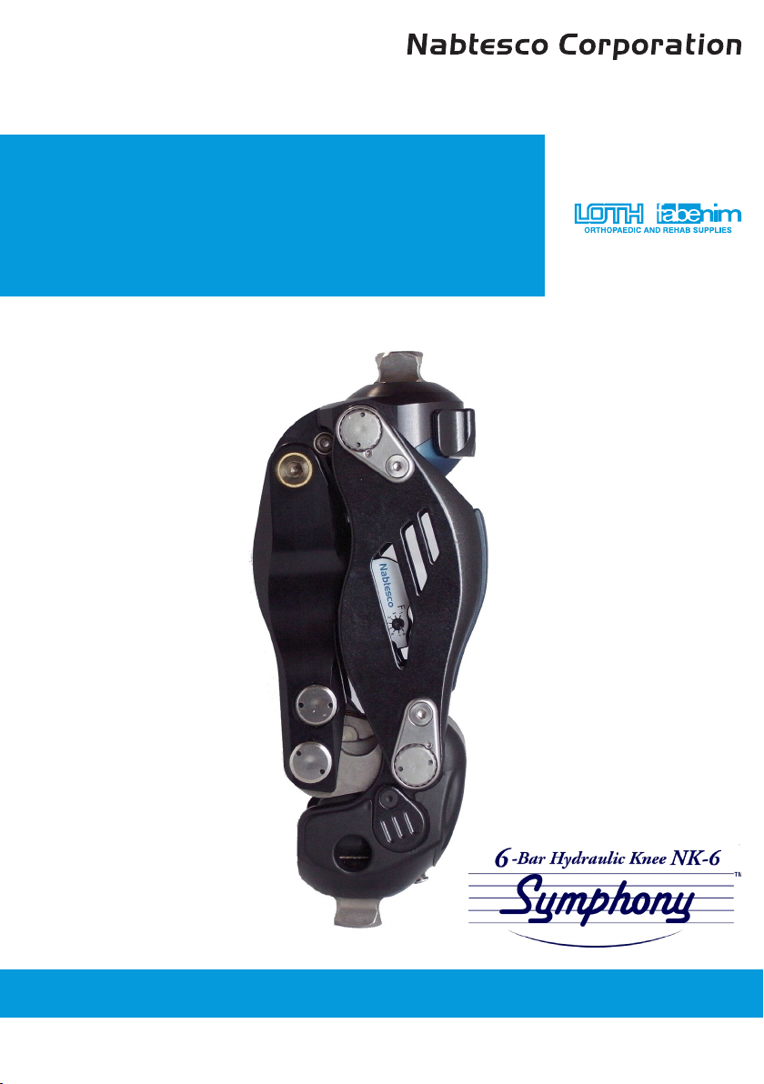
NK6 Symphony Knee van Nabtesco, distributeur Loth Fabenim B.V.
NK6 Symphony Knee Instruction Manual - For Prosthetists 7
Contents
1. Safety Precautions ................................................................................................................... 8
1.1 Contraindications ................................................................................................................ 8
1.2 Denition of Symbols .......................................................................................................... 8
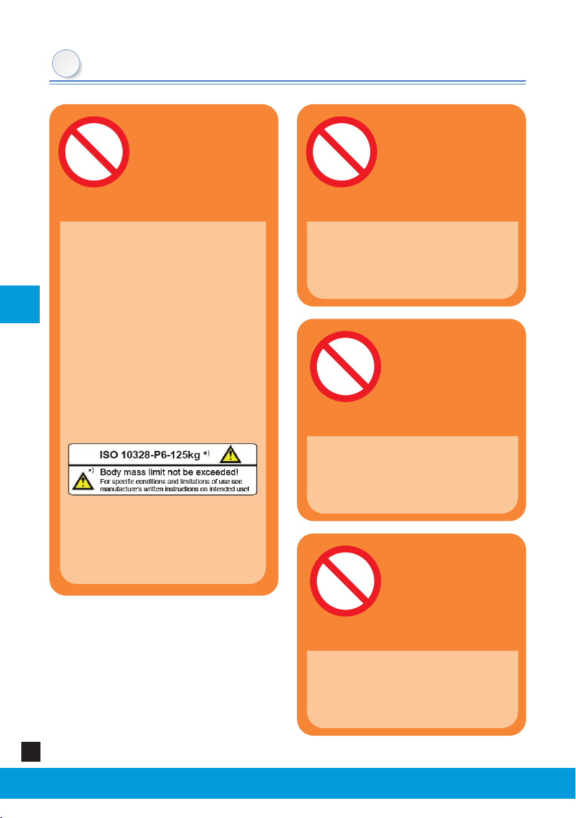
1.3 Mandatory Precautions ....................................................................................................... 9
1.4 Compatible medical devices (prosthesis components) ................................................. 12
2. Basic Construction and Operational Principle .............................................................. 13
2.1 Basic Construction ............................................................................................................. 13
2.2 Operational Principle ......................................................................................................... 13
2.3 Stance Phase Control ........................................................................................................ 14
2.4 Swing Phase Control .......................................................................................................... 15
3. Before Use ............................................................................................................................... 16
3.1 Scope of Delivery ............................................................................................................... 16
3.2 Assembly Procedure .......................................................................................................... 16
3.2.1 Static alignment ........................................................................................................ 16
3.2.2 Contact of socket at the maximum exion angle .................................................. 17
4. Adjustment .............................................................................................................................. 18
4.1 Adjusting the Stance Phase Control ................................................................................. 18
4.1.1 Adjusting the stance-exion rubber ....................................................................... 18
4.1.2 Adjusting the extension assist spring .................................................................... 19
4.2 Adjusting the Swing Phase Control .................................................................................. 20
4.2.1 Adjusting the exion resistance of hydraulic cylinder .......................................... 20
4.2.2 Adjusting the extension resistance of hydraulic cylinder .................................... 20
5. Operation Procedures and Precautions ......................................................................... 23
5.1 How to Activate the “Stance-Flexion” Function ............................................................... 23
5.2 Procedures for Operating the Selective Lock .................................................................. 24
5.3 Precautions for Operating the Selective Lock ................................................................. 25
5.4 Precautions When Sitting in and Standing up from a Chair ........................................... 26
6. Troubleshooting ..................................................................................................................... 27
7. Maintenance ............................................................................................................................ 29
7.1 Replacing the Extension Stopper Rubber ........................................................................ 29
7.2 Replacing the Stance-Flexion Rubber .............................................................................. 30
7.3 Removing the Base Bracket Cover ................................................................................... 31
7.4 Wiping O Dirt on the Surface .......................................................................................... 31
8. Outline of the Product .......................................................................................................... 32
9. Disposal .................................................................................................................................... 34
10. Symbols Used on Labels ..................................................................................................... 36
10.1 UDI Label (Packing Box) .................................................................................................. 36
10.2 Body Mass Limit Label (Knee Joint Body) ....................................................................... 37
10.3 Product Type Label (Knee Joint Body) ............................................................................ 37