Nabtesco Hybrid Knee NI-C3 Series User manual

Introduction
ThankyouforpurchasingNabtesco'sHybridKnee.
HybridKneeisatotallynewintelligentprostheticknee
jointtoprovidesafeandpleasantwalkingthrough
integrationofhydraulicandpneumaticcontroland
computercontrol.
Forsafeuse,besuretoreadthismanualandfamiliarize
yourselfwiththeHybridKnee.Carefullykeepthis
manualconvenientlyavailableforfuturereference.
AlsoreadthroughtheUser'sManualandgivethe
amputeesafetyinformationcontainedthereinbefore
handingittohim/her.
InstructionManual
(NI-C3 Series)
81-SS00076

1
TableofContents
1 SafetyPrecautions...................................................................................................................... 2
1-1 DefinitionofSymbols..................................................................................................... 2
1-2 “Must”ItemsforSafety .................................................................................................. 3
2 BasicConstructionandOperationalPrinciple ................................................................ 5
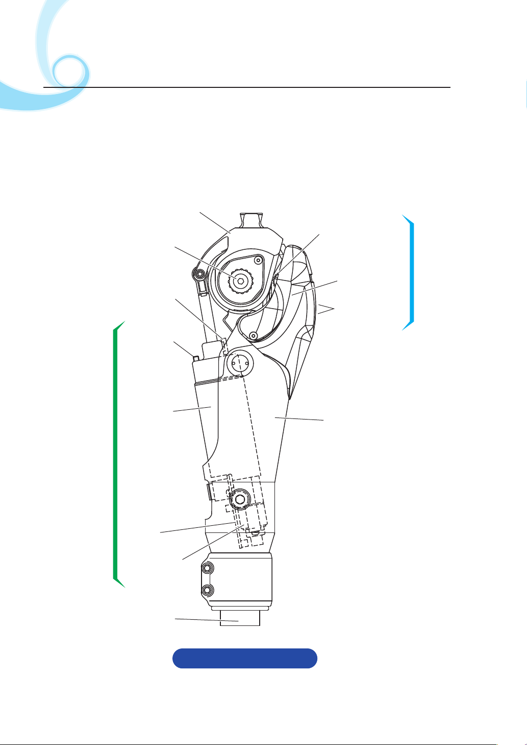
2-1 BasicConstruction........................................................................................................... 5
2-2 OperationalPrinciple......................................................................................................6
2-3 StancePhaseControl ..................................................................................................... 6
2-4 SwingPhaseControl ...................................................................................................... 7
3 BeforeUse ..................................................................................................................................... 9
3-1 ScopeofDelivery ............................................................................................................. 9
3-2 AssemblyProcedure....................................................................................................... 9
3-2-1 StaticAlignment.................................................................................................... 9
3-2-2 AssemblingtheTube.........................................................................................10
3-2-3 InsertingtheBatteryConnector....................................................................10
3-2-4 PrecautionsonSocketForming ....................................................................11
4 Adjustment .................................................................................................................................12
4-1 AdjustingtheStancePhaseControl ......................................................................12
4-1-1 AdjustingtheHydraulicResistance .............................................................13
4-1-2 WalkingonaLevelFloor ..................................................................................15
4-1-3 AdjustingSensitivity(OFF-timing)...............................................................16
4-2 AdjustingtheSwingPhaseControl........................................................................17
4-3 AdjustingYieldingforDescendingaSlopeorStairs.......................................19
4-4 PrecautionsWhenSittinginandStandingupfromaChair.........................21
5 Troubleshooting .......................................................................................................................22
6 Maintenance...............................................................................................................................24
6-1 ReplacingtheExtensionStopperRubber............................................................24
6-2 ReplacingtheBattery...................................................................................................25
6-3 ReplacingtheCylinderModule................................................................................27
7 OutlineoftheProduct............................................................................................................29
8 PeriodicInspectionandWarranty .....................................................................................30

2
1SafetyPrecautions
1-1 DefinitionofSymbols
WARNING
CAUTION
Prohibition
Mandatory
Action
Indicatesapotentiallyhazardoussituationcaused
bynonobservanceofthissymbolwhich,ifnot
avoided,couldresultinseriousinjury.
Indicatesapotentiallyhazardoussituationcaused
bynonobservanceofthissymbolwhich,ifnot
avoided,mayresultinminorormoderateinjuryor
propertydamage.
Indicatesageneralcautiontobeobserved.
Indicatesprohibitionofaspecificaction.
Indicatesobligationofaspecificaction.

3
WARNING
1-2 “Must”ItemsforSafety
Upondetectingany
abnormalnoise,play,or
dropinhydraulicresistance,
discontinueuseandcontact
yourlocalsales
representative/dealer.
Continuedusedespiteadetected
abnormalitymaycausedamageof
parts,leadingtofalling.
DONOTattemptto
charge,disassemble,
heat,short-circuit,ortoss
intothefireabattery.
Failuretoobservethiswarningcan
causeanexplosionorfiring.
DONOTplacethehand
behindthekneewhen
flexingtheknee.
DONOTtouchtheknee
whenextendingit.
Thehandcanbecaught,causing
injury.
Neverattemptto
disassembleormodify
HybridKnee.
Failuretoobservethiswarningcan
causebreakageofparts,leadingto
falling.
DONOTuseforaperson
whoweighsover100kg.
Ifusedtoapersonwhoweighsover
100kg,damageofpartsmayoccur,
leadingtofalling.This,however,does
notprecludeloadingandunloading
ofbaggage,etc.occurringindailylife.
Besuretohandthe
separateGuideforUse
directlytoauserand
explainprecautionsfor
use.
Improperusecancausefallingor
injury.
Prohibition
Prohibition Prohibition
Prohibition
Mandatory
Action
Mandatory
Action

4
CAUTION
Asocketshouldbeformed
andalignedsothatneither
thesocketnoranyother
partcontactsthe
pneumaticcylinderatthe
maximumflexionangle.
Itwillleadtodamageofthepneu-
maticcylinder,impedingnormal
walking.
DONOTimmerseinany
liquidsuchaswaterand
seawater.
Failuretoobservethiscautionwill
causerustonparts,resultinginfailure
oftheunit.
DONOTdroppartssuch
asascrewintheframe.
Continueduseafteranypartis
droppedwillcausedamageofa
pneumaticcylinder,impedingnormal
walking.
Besuretoattendthe
operationtrainingcourse
offeredbyyourlocalsales
representative/dealer.
Incorrectadjustmentcannever
providepleasantwalking.
Besuretoundergo
periodicinspectionevery
year.
IftheHybridKneeisusedwithout
inspection,partsabrasioncanbe
accelerated.
Prohibition
Prohibition
Prohibition
Mandatory
Action
Mandatory
Action

5
Kneeplate
Proximitysensor
Hydraulicrotary
damper
MRSsystem
Adjustingplug
(Seepage12.)
Carbonframe
Rotaryaxis
(Kneeaxis)
Cushionvalve
Pneumatic
cylinder
Swingphasecontrolsection
Printed
circuitboard
Steppingmotor
Battery
Stancephasecontrolsection
2BasicConstructionand
OperationalPrinciple
2-1 BasicConstruction
HybridKneehasaccomplishedsophisticatedintegrationofthehydraulic
rotarydampertocontrolthestancephase,theMRSsystem,andthe
microprocessor-controlledpneumaticcylinderfortheswingphase.
Fig.1MainComponents

6
Hydraulic
rotarydamper Pneumatic
cylinder
Sensingpoint
HydraulicresistanceisON. HydraulicresistanceisOFF.
2-2 OperationalPrinciple
Thehydraulicrotarydamperreliablyfunctionswhiletheprosthesisisin
contactwiththefloor,thuspreventingabruptbuckling.Whentheprosthesis
leavesthefloor,themicroprocessor-controlledpneumaticcylinderfunctions,
providingcadenceresponsiveswingcontrol.
2-3 StancePhaseControl
Whenakneeisflexed,thehydraulicrotarydamperproduceshydraulic
resistance,thuspreventingabruptbucklingtooccur.TheMRS(Mechanism
ofReactionForceSensing)systemmechanicallydetectsfloorreactionforce
andsetsON/OFFofhydraulicresistance.Whenfloorreactionforceexistsat
theheelsidefromthesensingpoint,hydraulicresistanceisturnedon.When
itexistsatthetoeside,thehydraulicresistanceisturnedoff.
Fig.2LevelFloor
Fig.3MRSSystem

7
● Yieldingfunction
Byhavingtheheellandfirst,anamputeecan
slowlyflexthekneewhileapplyingbodyweight
totheknee.Aftergettingfamiliarwiththe
yieldingfunction,heorshecanperformvarious
actssuchasdescendingaslopeandstairs.
Note:HybridKneeisintendedtoassistcapabilityofapersonwhousesa
prosthesis.Withoutpropergaittraining,nobodyisabletodescenda
steepslopeorstairs.
Inordertomakeyieldingfunctioneffective,be
suretostrikethefloorwiththeheelfirst.Ifyou
strikethefloorwiththetoefirst,hydraulic
resistanceisturnedoffandthebodyweight
cannotbesupported.Thereisariskthatknee
bucklingmaytakeplace,causingfalling-down.Forsafeuse,fullyunderstand
theoperationalprincipleandproperwalkingmethod,andprovidethe
amputeewithinstructions.JSee
Fig.4Stairs
POINT1(page15).
Timeforonecycle
Stancephase
OFF OFF
ON
8°
Swingphase
8°
2-4 SwingPhaseControl
Themicroprocessor
calculatesthetimefor
onewalkingcycleby
usingdataonkneejoint
flexionasdetectedby
theproximitysensor.
Also,thismicroproces-
sormemorizesforeach
amputeetheadjusting
dataonthemaximum
10stageswhichconsist
ofcadenceandreaction
forceofthepneumatic
cylinder.Whencadencechanges,themicroprocessorcommandsthestep-
pingmotortoactivatetheneedlevalveimmediatelysothataswingspeedof
theprosthesisisselected.
Fig.5
WARNING

8
WalkingSpeed
(Slow) (Fast)
30
0
Valveopening
(Cylinderreactionforce)
(Low)
(High)
MT FT
ST
SV
MV
FV
Slow
Fast
V1
V2
V3
V4
V5
V7
B9
V6
V8
B6 B5 B4 B3 B2 B1
V9
V10
B8 B7
Normal
● Datastore
Asadjustmentdataisstoredinthememory,itwillnotbedeletedevenifthe
batteryconnectorispulledout.Inotherwords,readjustmentisnotrequired
evenwhenthebatteryisreplaced.
● Whenwalkingstops
Whenanamputeestopswalkingfor8secondsormore,theneedlevalveis
automaticallysettothehis/hernormalcadence.
● Whenthebatteryisrunninglow
Whenremainingbatterypowerisreduced,theneedlevalveisautomatically
settothehis/hernormalcadence.Afterthat,itcannotrespondtoacadence
changebutanamputeecanwalkataconstantspeed.
Fig.610-StageSetting

9
0to10mm
3BeforeUse
3-1 ScopeofDelivery
3-2 AssemblyProcedure
3-2-1
StaticAlignment
● Alignmentoffrontalplane
Performstaticalignmentaccordingtothe
followingprocedure.
Completealignmentsothattheloadline
passesthroughthecenterofthekneejoint
andfallsintheheelcenterofthefootsection.
● Alignmentofsagittalplane
AsshowninFig.7,completealignmentso
thattheweightloadlinepassestherangeof
0to10mminfrontofthecenterofthe
kneeaxisofthekneejoint.
・Hybridknee ・・・・・・・・・・・・・・・・・・・・・・・1
・Dedicatedlithiumbattery ・・・・・・・・・・・1(alreadyset)
・Userʼsmanual・・・・・・・・・・・・・・・・・・・・・・1
(Afterexplainingthecontent,handitdirectlytotheamputee.)
・Instructionmanual(thisbook) ・・・・・・・1
Pleaseconfirmthatthefollowingitemsareincluded.
Whentherecommendedalignmentisout
ofline,excessloadisimposedtotheparts,
acceleratingwear.
Forahipprosthesis,useofatorsion
adapterisrecommended. Fig.7
CAUTION

10
Outerclamp
Innerclamp
Batteryconnector
Clampingbolt
Tube
Batteryconnector
Circuitboard
connector
Thebatteryconnectorhas
beendisconnectedforship-
ment.TousetheHybridKnee,
besuretoinsertthebattery
connectorintothecircuit
boardconnector.
3-2-2
AssemblingtheTube
3-2-3
InsertingtheBatteryConnector
Forsafeuse,youarerecom-
mendedtousethetubemade
byNabtesco.Whenusingone
madebyanyothermanufac-
turerduetounavoidablecircum-
stances,besuretouseonewhose
outsidedimensiontoleranceis
within+/-0.05mm.
Beforeinsertingthebattery
connector,besuretoelimi-
natestaticelectricityby,for
example,touchingadesk.
・Connectingtheadjustmentunit,performreset.
・Confirmthatmotorsoundisnormal.
*Whenthemotorcontinuestorun,performtheresetoperation.(Thereis
ariskthatbatteryelectricitymaybeabnormallyconsumed.)
Fig.8aAssemblingtheTube
Fig.8bInsertingtheBatteryConnector
1 Looseningtheouterclampbolts,insertthetubeintotheinnerclampand
pushthetubeuntilithitsthestopperoftheinnerclamp.
2 Whenassemblingthetube,besuretoalignthesplitgrooveoftheouter
clampwiththatoftheinnerclamp.
3 Tightentheboltstoatorqueof
4.5to5.0N・m.
CAUTION
CAUTION
CAUTION

11
3-2-4
PrecautionsonSocketForming
Fig.9
Atthetimeofsocketforming,make
surethatneitherthesocketnor
partstouchthepneumatic
cylinderwhenthekneejoint
isflexedtothefullestextent.
Failuretodosomaycause
damagetothepneumatic
cylinder,adverselyaffecting
thefunction.
CAUTION
Avoid
interference.
Pneumatic
cylinder

12
Hydraulic
resistance
adjustingplug
Adjusting
plug
Resistance Yieldingstrength
(Hydraulicresistance)
Differentbodyweightand
activitylevel
Sensitivity
(OFF-timing)
Increasingeffectiveness
andsustainability(OFF-
timing)ofyielding
function.
Atthetimewhenstickingoccurs
duringtransitingtostancephase.
Atthetimewhentheyield
durationisinsufficient
Effect Whentoperform
adjustment
A
Hydraulic
sensitivity
adjustingplug
B
A
B
Time
Hydraulicresistance
Strength
A
Time
Hydraulicresistance
OFF-timing
B
4Adjustment
4-1 AdjustingtheStancePhaseControl
First,adjustthestancephase
control.Asthehydraulic
damperhastwokindsof
adjustingplugs,asshownin
Fig.10andTable1.
Fig.10LocationoftheAdjustingPlugs
Table1HowtoSelectAdjustingPlugs

13
10
5
0
15
Mark
Hexwrench
(3mm)
4-1-1
AdjustingtheHydraulicResistance
Insertingahexwrenchobliquelyupwardintothehydraulicresistance
adjustingplug,turnittochangehydraulicresistance.
・Clockwise(Scalereadingsbecomesmall.):
Hydraulicresistancebecomeshigheratthestancephase.
・Counterclockwise(Scalereadingsbecomelarge.):
Hydraulicresistancebecomesloweratthestancephase.
Adjustbyusingscalereadingsasaguide.Readthescaleatthemarkonthe
window.
Fig.11HowtoAdjustHydraulicResistance
Adjustingscaleasviewed
throughthewindow(for10)
Theadjustingplugshavebeensettothepositionswhicharecommon
tomostpeopleinthefactorydefaultsetting.
Whenyoucannotfindsuitablepositions,turntheplugstotheir
originalposition.
Hydraulicresistanceadjustingplug: Settothescale10.
Hydraulicsensitivityadjustingplug: Settothescale15.
IMPORTANT
A
B

14
Fig.12
Threemethodsareavailableaccordingtoapplicationofbodyweight:
Whenbodyweightisappliedtotheheel,yieldingfunctioncanwork.
Whenbodyweightisappliedtothetoe,yieldingfunctioncannotwork.
Afterfullyapplyingbodyweighttotheheel,whenanamputeeshifts
bodyweighttowardthetoewhileyieldingfunctionisretained,
hydraulicresistanceissustainable.
POINT1: HowtoObtainYieldingFunction
A
A B C
B
C
YieldingON OFF ON
Bodyweightshift
ON
Sustainable
1Makesurethatthescalereads10attheprojection
onthewindow.Thenlettheamputeestandwithin
parallelbars.(Fig.12)
3Havetheamputeefeeltwodifferentlevelsof
yieldingstrengthbyadjustingthescaleasfollows.
(1)Scalereading0*(strongest)
(2)Scalereading15(weak)
*:Thereading“0”iswheretheplugisfullyclosedby
turningclockwise.
Procedure
2Havetheamputeeplacehisorherweightonthe
prosthesisandconfirmthatyieldingfunction
worksproperly.JSee
.
POINT1
4Takingthereading10asthebenchmark,finelyadjusttheadjustingplug
andchooseadesirablelevelofstrength.JSee
.
POINT2

15
4-1-2
WalkingonaLevelFloor
DONOTusereadingsof19andabove.Whentheplugisloosenedonefull
turnormorefromthefullyclosedposition(reading0),ariskofoilleakageis
created.Oilresistancedoesnotchangeeveniffurtherlooseningisadded.
1Lettheamputeewalkwithintheparallelbars.Providepracticesothat
theamputeefullyextendsthekneejointintheinitialstancephasein
normalwalkingonalevelfloor.
2Confirmthatthereisnostickingcausedbyyieldingfunctionatthetime
oftransitionfromstancephasetoswingphase.
3Whentheamputeebecomesfamiliarwithwalking,performgaittraining
outsidetheparallelbars.Whenstickingoccurs,makeanadjustment
accordingtothetroubleshootingmethod(seepages22and23).
・Althoughhydraulicresistancevariesby
weightandactivity,thestandardlevelis
generallybetween5and15.Ifyouarenot
sure,setitto10.
・Hydraulicresistancemaybefeltweaker
duetoinsufficientheelload.
Providesufficientgaittrainingfor.
POINT2:
GuideforIntensityofHydraulicResistance
Fig.13
POINT1
5
0
15
10
CAUTION
Provideappropriatealignment,footselection,andgaittrainingsothatan
amputeecanfullyapplyhisorherbodyweighttotheheel.Whenheelload
isinsufficient,yieldingfunctionmaynotbesustainable.
CAUTION

16
Themaximumadjustablerangeofthesensitivityadjustingplugisone
looseningturnfromthefullyclosedposition.Thefactorydefaultisset
tothescale15.Whenyoucannotfindanappropriateposition,itis
recommendedthattheprosthesisisusedinthefactorydefaultsetting.
IMPORTANT
Neverloosenthesensitivityadjustingplugmorethanoneturnfromthefully
closedposition.Theplugisdesignedforanti-dropping.Iftheplugis
loosenedmorethanoneturn,thepartsmaybedamaged.
Sensitivityissettothestandardconditionatthefactory.
Whennoproblemexists,adjustmentisunnecessary.
Fig.14AdjustingSensitivity
Referringtothefigurebelow,turnthesensitivityadjustingplugonthe
right-handsidebyusingahexwrench.Whentheplugisturned,hydraulic
resistancewillchangeasfollows:
Clockwise(forward): Yieldingfunctionbecomesmoreeffectiveand
moresustainable.
Counterclockwise(rearward)
:Yieldingfunctionbecomeslesseffectiveand
lesssustainable.
4-1-3
AdjustingSensitivity(OFF-timing)
ReferringtoTable1(seepage12),performsensitivityadjustment.
CAUTION
15
10
5
0
Mark
Hexwrench
(3mm)
Adjustingscaleasviewed
throughthewindow(for15)

17
4-2 AdjustingtheSwingPhaseControl
Enterwalkingdataintothemicroprocessortoenablechangesincadence.As
foradjustmentprocedure,refertotheseparateadjustmentinstructionmanual.
Whenundesiableterminalimpactoccurs,adjustthecushionvalvelocated
abovethepneumaticcylinderinthefollowingprocedure:
● Programmingforswingphase
● Adjustingterminalimpact
Fig.15FixingProcedureoftheCushionValve
1AsshowninFig.15,turnthecushionvalvewithahexwrench(2mm).
Clockwise:Cushioneffectisenhancedandimpactisreduced.
Counterclockwise:Cushioneffectisweakenedandimpactisincreased.
2Lettheamputeewalkslowlybysecuringsafetywithparallelbarsand
confirmthatthekneeextendsfully.
Ifthekneedoesnotfullyextend,turnthecushionvalvetotheleftto
weakencushioneffect.
3Lettheamputeegraduallyincreasehisorhercadence.Confirmingsound
levelofterminalimpact,selectanappropriatevalveposition.

18
Neverusetheprosthesiswithexcessivelystrongcushioneffect.Failureto
observethiscautioncancausefallingasthekneedoesnotextendfully.
Also,itmaycauseyieldingfunctiontoworkunintentionally,resultingin
sticking.
・Cushionadjustmentshould
bemadeinconsiderationof
swingstrengthofeach
amputee.Asageneralrule,
however,settothevaluein
themarkedrange.
・Thefactorydefaultsetting
is1turntotheleftfromthe
fullyclosedposition.
POINT3: GuidetoCushionAdjustment
Fig.16
CAUTION
-360°
(Factory
default
setting)
-180°

19 Fig.17aDescendingaSlope Fig.17bDescendingStairs
Beforedescendingaslopeorstairs,performfineadjustmentsofhydraulic
resistanceandsensitivity.
Concerninguseforwalkingonaslopeorstairs,anamputeeshouldbefully
instructedtosecuresafetybyholdingahandrail.Asfloorconditionsarenot
good,thereisariskthattheamputeemaylosebalance,resultingin
falling-down.
Inordertomaketheyieldingfunctioneffective,besuretotouchthefloor
withtheheelfirst.Ifthetoetouchesthefloorfirst,thereisariskof
occurrenceofkneebuckling,resultinginfalling-down.
Beforeusingtheprosthesisforwalkingonaslopeorstairs,performgait
training.
Ifappropriateuseofyieldingisjudgeddifficultaftergaittraining,useof
yieldingfunctionshouldbeprohibited.Failuretoobservethisinstruction
maycauseaseriousaccidentsuchasfalling-down.
WARNING
Mandatory
Action
4-3
AdjustingYieldingforDescendingaSlopeorStairs
This manual suits for next models
4
Table of contents
Other Nabtesco Medical Equipment manuals

Nabtesco
Nabtesco Symphony NK-6 User manual

Nabtesco
Nabtesco Symphony NK-6 User manual

Nabtesco
Nabtesco Symphony NK-6 User manual

Nabtesco
Nabtesco ALLUX NE-Z4 User manual

Nabtesco
Nabtesco ALLUX NE-Z4 User manual

Nabtesco
Nabtesco Symphony NK-6 User manual

Nabtesco
Nabtesco ALLUX User manual

Nabtesco
Nabtesco N-D231 User manual

Nabtesco
Nabtesco Symphony NK-6 User manual

Nabtesco
Nabtesco HybridKnee NI-C3 Series User manual