manuals.online logo
Brands
  1. Home
  2. •
  3. Brands
  4. •
  5. NAPCO
  6. •
  7. Keypad
  8. •
  9. NAPCO Gemini GEM-P816 User manual

NAPCO Gemini GEM-P816 User manual

GEM-TOUCH Keypad Installation Instructions 1
push the wire back into the drilled wall center hole until the rear
case is flat against the wall surface. Insert screws through the
rear case mounting holes and secure.
If replacing an existing Gemini keypad: Use the Wall Plate
Adapter instructions on page 2. Use the existing 4-wire or 14-
pin harness.
If installing onto a double-gang box: Insert mounting
screws through the two vertical elongated holes on the left side
of the case and into the box. If the box is visible when viewed
from the front, adjust the keypad vertically and tighten the
screws. Then, using hardware suitable for the mounting
surface, add one or two screws at the right side of the keypad
case directly into the wall.
Note: Do not over tighten the mounting screws! An uneven
surface may cause the keypad case to distort.
Assemble the keypad by placing the top edge of the keypad
front case over the two hooks at the top of the rear case. Push
the bottom of the keypad until it snaps together.
OPTION JUMPER
Cut wire loop W1 to enable S1 tamper switch.
DESCRIPTION
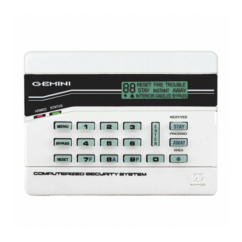
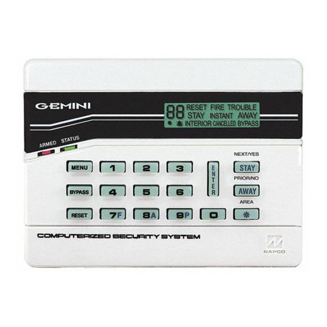
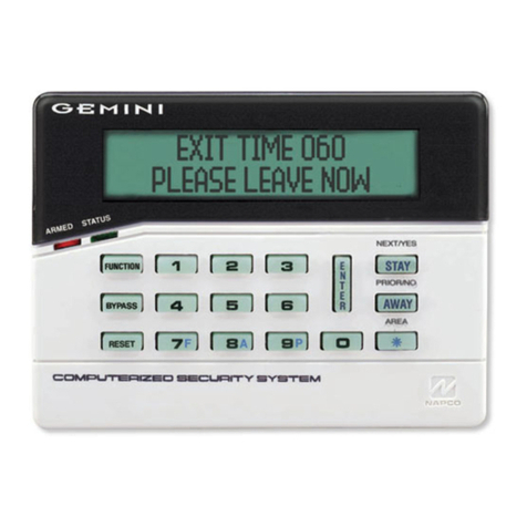
The GEMINI GEM-TOUCH keypad is compatible with the
NAPCO Gemini Series GEM-P816, GEM-P1632, GEM-
P1664, GEM-P3200, GEM-X255 and GEM-P9600. Note: For
systems with multiple keypads, all keypads must be all
"classic" (GEM-RP prefix) or all "K Series" (GEM-K prefix).
Keypad types cannot be mixed.
SPECIFICATIONS
See product label.
Boot Current: 249mA peak
Nominal Operating Current: 148mA peak
Current During USB Update: 198mA peak
PGM: Maximum 5mA, +12V nominal.
Environmental: 32°F to 122°F (0°C to 50°C)
INSTALLING THE KEYPAD
Requires power from the control panel bus (observe current
limitations) or an un-switched separate power supply (panel
ground must be common with power supply ground). Select a
location that allows the power wires to be hidden within the
mounting surface. Requires a battery backup power source to
avoid troubles if power is interrupted. Mount a keypad near
each exit/entry door (indoors locations only). In Residential
Fire Installations, Home Run all keypads. Note: The keypad
fire and panic buttons are not a substitute for a listed manual
initiating device (such as a pull box).
Do not power the keypad during the mounting process. De-
tach the rear case by pressing the two push-tabs at the bot-
tom, then unhook and detach.
For new installations: Use the rear case as a template to
mark the mounting holes (always use a level to ensure hori-
zontal mounting). Mark the center hole for the power wire,
then use a 1/2" drill bit to drill the center hole. Snake the pow-
er wire inside the wall and out through the drilled center hole.
If mounting to hollow drywall or similar surface, we recommend
using wall anchors or similar hardware appropriate for the in-
stallation. Firmly connect the power wire connectors and then
GEM-TOUCH Keypad
Installation Instructions
© NAPCO 2021 WI2479CLF 12/21
333 Bayview Avenue, Amityville, New York 11701
For Sales and Repairs, (800) 645-9445
For Technical Service, (800) 645-9440 or visit us at
Tech.NapcoSecurity.com
(Note: Technical Service is for security professionals only)
Publicly traded on NASDAQ Symbol: NSSC
REMOTE BUS
All Zone End of Line
Resistors are 2.2KΩ
BROWN
PGM
12V
(To control panel)
Tap/Hold-down
Tap/Hold-down
SYSTEM READY 1
09/14/28 8:15PM
(GEM-TOUCH Keypad)
WIRING FOR GEM-TOUCH
Disconnect power source before wiring to terminals
COLOR FUNCTIONPANEL TERMINAL
RED 12V PWR9
BLACK PWR GND10
GREEN KEYPAD RX11
YELLOW KEYPAD TX12
BROWN PGM OUTPUT
Max 5mA, +12V Nominal
--
GRAY ZONE COMMON--
ORANGE ZONE 1--
BLUE ZONE 2--
GRAY ZONE COMMON--
VIOLET ZONE 3--
WHITE ZONE 4--
GRAY ZONE COMMON--
Important Note: The GEM-TOUCH keypads cannot be used for control panel programming.
2GEM-TOUCH Keypad Installation Instructions
CONFIGURING THE GEM-TOUCH
A total of up to 15 GEM-TOUCH keypads may be connect-
ed to the control panel. Each GEM-TOUCH keypad can be
configured for its keypad address, EZM address and zone
response.
Enter System Settings
1. At the keypad Home screen, tap the
System Settings ("gears") icon (shown
at right).
2. Using the number buttons that appear,
enter the Keypad Configuration Code
(1 1 1 2 3), followed by Enter.
3. In the System Settings screen, tap Dealer KP Config:
The following screen appears:
EZM Config
The keypad's internal EZM (Expansion Zone Module) may
be utilized to provide four additional wired zones. Whether
used alone or in conjunction with optional GEM-EZM se-
ries modules or other keypad EZMs, it must be assigned a
unique address (or Group number, see the control panel
Programming Instructions) similar to its keypad address. If
no other EZMs are to be used, set "0" (disabled) for Set
EZM Address. In multiple-EZM systems, enter an as-
signed group number "1" through "22". (Each EZM must
have a unique assigned group number, starting with "1"
and proceeding consecutively). Tap Save to continue or
tap Exit to return to the previous screen without saving
your changes.
Zone Response
The normal loop response of each keypad expansion zone
is 750mS, however the response time of any zone can be
reduced to 50mS by simply adding a check to the ckeck-
box for the selected 50mS zone (tap to add a check).
When finished, tap Save to continue or tap Exit to return to
the previous screen without saving your changes.
Keypad Config (Keypad Address)
If more than one keypad is installed, each must be as-
signed a unique keypad address (that is, no two keypads
may be numbered alike). Note: From the factory, the
GEM-TOUCH keypad is addressed as "00", not "01" like
our other Gemini GEM-RP1 or GEM-K1 keypads. In addi-
tion, please note:
• Keypads must be numbered consecutively (missing
numbers are not permitted)
• Only Keypad No. 1 may be used for User program-
ming.
To assign the keypad number, proceed as follows:
1. Tap the Set KP Address number button.
2. Using the number buttons that appear, enter the Keypad
number (1-7), followed by Enter.
• Ensure that the new number selected appears on the
Set KP Address button. A valid number will be
acknowledged by a short beep; an invalid number
will be rejected by a long beep.
3. Tap Save to continue or tap Exit to return to the pre-
vious screen without saving your changes.
Keypad Model Type
Use the K_KP checkbox to configure the GEM-TOUCH to
operate as either a "classic" model GEM-Rp1CAe2 or as a
"K Style" GEM-K1CA by adding or removing a check, as
follows:
• Add a check for the "K Style"
model GEM-K1CA
• Remove check for the "classic"
model GEM-Rp1CAe2
Tap Save to continue or tap Exit to return to the previous
screen without saving your changes.
System Settings
("gears") icon
K_KP
K_KP
GEM-TOUCH Keypad Installation Instructions 3
Installing the GEM-TOUCH Wall Plate Adapter
The GEM-TOUCH Wall Plate Adapter allows you to easily cover the larger
Gemini "RP classic" or "K-series" keypad footprint with the smaller GEM-
TOUCH Color Security Touchscreen Keypad (shown at right). The
mounting plate is optional for new GEM-TOUCH installations.
The Wall Plate Adapter can be mounted directly to a wall using the exist-
ing keypad mounting holes or to an existing 2-gang or single-gang electri-
cal box. Finishing "screw caps" press into each screw hole after mount-
ing. Mount the keypad rear housing to the Wall Plate using two screws,
provided.
The existing keypad wire harness plug must extend several inches from
the wall, through the Wall Plate Adapter opening, in order to reach the
new GEM-TOUCH keypad header socket. If longer wires are needed, splice in the included wire harness
plug (part W834J-1), ensuring each wire color splice matches the existing wire colors. Note: Remove
power prior to splicing.
2-Gang Box
Wall Plate
(front shown)
GEM-TOUCH
keypad rear
housing
Wall Plate
(rear)
Drill-thru bosses
(x4) for mounting
to Gang boxes
Two #6 x 3/8"
Phillips pan head
mounting screws
(provided)
Finishing
screw caps
To mount to a 2-gang box (shown at
left), drill through the four bosses located
on the rear of the Wall Plate. If mount-
ing to a single-gang box, drill through
two of the rear bosses only. Note: We
recommend using countersink screws
when mounting the plate to a gang box.
Be sure to drill a countersink hole in the
plastic to ensure the screw head does
not interfere with the GEM-TOUCH key-
pad rear housing. At the end of the in-
stallation, ensure the keypad is level.
Note: See the User's Guide
for the NAPCO Limited Warranty.
GEM-TOUCH Color Security
Touchscreen Keypad
Tap/Hold-down
Tap/Hold-down
SYSTEM READY 1
09/14/28 8:15PM
4GEM-TOUCH Keypad Installation Instructions
NAPCO SECURITY TECHNOLOGIES, INC.
(NAPCO) warrants its products to be free from
manufacturing defects in materials and workmanship
for thirty-six months following the date of manufacture.
NAPCO will, within said period, at its option, repair or
replace any product failing to operate correctly without
charge to the original purchaser or user.
This warranty shall not apply to any equipment, or any
part thereof, which has been repaired by others,
improperly installed, improperly used, abused, altered,
damaged, subjected to acts of God, or on which any
serial numbers have been altered, defaced or
removed. Seller will not be responsible for any
dismantling or reinstallation charges.
THERE ARE NO WARRANTIES, EXPRESS OR
IMPLIED, WHICH EXTEND BEYOND THE
DESCRIPTION ON THE FACE HEREOF. THERE IS
NO EXPRESS OR IMPLIED WARRANTY OF
MERCHANTABILITY OR A WARRANTY OF
FITNESS FOR A PARTICULAR PURPOSE.
ADDITIONALLY, THIS WARRANTY IS IN LIEU OF
ALL OTHER OBLIGATIONS OR LIABILITIES ON
THE PART OF NAPCO.
Any action for breach of warranty, including but not
limited to any implied warranty of merchantability,
must be brought within the six months following the
end of the warranty period. IN NO CASE SHALL
NAPCO BE LIABLE TO ANYONE FOR ANY
CONSEQUENTIAL OR INCIDENTAL DAMAGES
FOR BREACH OF THIS OR ANY OTHER
WARRANTY, EXPRESS OR IMPLIED, EVEN IF THE
LOSS OR DAMAGE IS CAUSED BY THE SELLER'S
OWN NEGLIGENCE OR FAULT.
In case of defect, contact the security professional
who installed and maintains your security system. In
order to exercise the warranty, the product must be
returned by the security professional, shipping costs
prepaid and insured to NAPCO. After repair or
replacement, NAPCO assumes the cost of returning
products under warranty. NAPCO shall have no
obligation under this warranty, or otherwise, if the
product has been repaired by others, improperly
installed, improperly used, abused, altered, damaged,
subjected to accident, nuisance, flood, fire or acts of
God, or on which any serial numbers have been
altered, defaced or removed. NAPCO will not be
responsible for any dismantling, reassembly or
reinstallation charges.
This warranty contains the entire warranty. It is the
sole warranty and any prior agreements or
representations, whether oral or written, are either
merged herein or are expressly cancelled. NAPCO
neither assumes, nor authorizes any other person
purporting to act on its behalf to modify, to change, or
to assume for it, any other warranty or liability
concerning its products.
In no event shall NAPCO be liable for an amount in
excess of NAPCO's original selling price of the
product, for any loss or damage, whether direct,
indirect, incidental, consequential, or otherwise arising
out of any failure of the product. Seller's warranty, as
hereinabove set forth, shall not be enlarged,
diminished or affected by and no obligation or liability
shall arise or grow out of Seller's rendering of
technical advice or service in connection with Buyer's
order of the goods furnished hereunder.
NAPCO RECOMMENDS THAT THE ENTIRE
SYSTEM BE COMPLETELY TESTED WEEKLY.
Warning: Despite frequent testing, and due to, but not
limited to, any or all of the following; criminal
tampering, electrical or communications disruption, it
is possible for the system to fail to perform as
expected. NAPCO does not represent that the
product/system may not be compromised or
circumvented; or that the product or system will
prevent any personal injury or property loss by
burglary, robbery, fire or otherwise; nor that the
product or system will in all cases provide adequate
warning or protection. A properly installed and
maintained alarm may only reduce risk of burglary,
robbery, fire or otherwise but it is not insurance or a
guarantee that these events will not occur.
CONSEQUENTLY, SELLER SHALL HAVE NO
LIABILITY FOR ANY PERSONAL INJURY,
PROPERTY DAMAGE, OR OTHER LOSS BASED
ON A CLAIM THE PRODUCT FAILED TO GIVE
WARNING. Therefore, the installer should in turn
advise the consumer to take any and all precautions
for his or her safety including, but not limited to,
fleeing the premises and calling police or fire
department, in order to mitigate the possibilities of
harm and/or damage.
NAPCO is not an insurer of either the property or
safety of the user's family or employees, and limits its
liability for any loss or damage including incidental or
consequential damages to NAPCO's original selling
price of the product regardless of the cause of such
loss or damage.
Some states do not allow limitations on how long an
implied warranty lasts or do not allow the exclusion or
limitation of incidental or consequential damages, or
differentiate in their treatment of limitations of liability
for ordinary or gross negligence, so the above
limitations or exclusions may not apply to you. This
Warranty gives you specific legal rights and you may
also have other rights which vary from state to state.
NAPCO LIMITED WARRANTY
Other manuals for Gemini GEM-P816

3

This manual suits for next models

6

Other NAPCO Keypad manuals

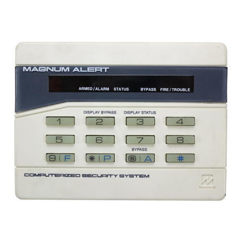
NAPCO MAGNUM ALERT RP2000 KEYPAD User manual

NAPCO

NAPCO MAGNUM ALERT RP2000 KEYPAD User manual

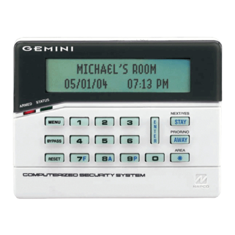
NAPCO Gemini GEM-RP4C User manual

NAPCO

NAPCO Gemini GEM-RP4C User manual

NAPCO RP1016LCD User manual

NAPCO

NAPCO RP1016LCD User manual

NAPCO MAGNUM ALERT RP1016E KEYPAD User manual

NAPCO

NAPCO MAGNUM ALERT RP1016E KEYPAD User manual

NAPCO Gemini GEM-RP3DGTL User manual

NAPCO

NAPCO Gemini GEM-RP3DGTL User manual

NAPCO Gemini GEM-K4 User manual

NAPCO

NAPCO Gemini GEM-K4 User manual

NAPCO RP1054e User manual

NAPCO

NAPCO RP1054e User manual

NAPCO RP1000LCD User manual

NAPCO

NAPCO RP1000LCD User manual

NAPCO RP1054e User manual

NAPCO

NAPCO RP1054e User manual

NAPCO MAGNUM ALERT RP1016E KEYPAD User manual

NAPCO

NAPCO MAGNUM ALERT RP1016E KEYPAD User manual

NAPCO GEM-RP1CAE KEYPAD User manual

NAPCO

NAPCO GEM-RP1CAE KEYPAD User manual

NAPCO GEMINI C Series Installation manual

NAPCO

NAPCO GEMINI C Series Installation manual

NAPCO MAGNUM ALERT RP3000 KEYPAD User manual

NAPCO

NAPCO MAGNUM ALERT RP3000 KEYPAD User manual

NAPCO Magnum Alert RP2000LCD User manual

NAPCO

NAPCO Magnum Alert RP2000LCD User manual

NAPCO RPXP6GT User manual

NAPCO

NAPCO RPXP6GT User manual

NAPCO Gemini GEM-K4RF User manual

NAPCO

NAPCO Gemini GEM-K4RF User manual

NAPCO GEM-RP8LCD User manual

NAPCO

NAPCO GEM-RP8LCD User manual

NAPCO MAGNUM ALERT RP1016D KEYPAD User manual

NAPCO

NAPCO MAGNUM ALERT RP1016D KEYPAD User manual

NAPCO MAGNUM ALERT RP1000E LCD KEYPAD User manual

NAPCO

NAPCO MAGNUM ALERT RP1000E LCD KEYPAD User manual

NAPCO Security System User manual

NAPCO

NAPCO Security System User manual

NAPCO Gemini GEM-DXRP3 User manual

NAPCO

NAPCO Gemini GEM-DXRP3 User manual

NAPCO MAGNUM ALERT RP1000E LCD KEYPAD User manual

NAPCO

NAPCO MAGNUM ALERT RP1000E LCD KEYPAD User manual

NAPCO Gemini GEM-RP3DGTL User manual

NAPCO

NAPCO Gemini GEM-RP3DGTL User manual

NAPCO MAGNUM ALERT RP1016 LCD KEYPAD User manual

NAPCO

NAPCO MAGNUM ALERT RP1016 LCD KEYPAD User manual

Popular Keypad manuals by other brands

Nidac PRESCO PRE Series user guide

Nidac

Nidac PRESCO PRE Series user guide

Dorma AC-228 Installation & programming manual

Dorma

Dorma AC-228 Installation & programming manual

Tunstall Keypad Installer Quick Reference Card

Tunstall

Tunstall Keypad Installer Quick Reference Card

ADEMCO 6150PL3 installation guide

ADEMCO

ADEMCO 6150PL3 installation guide

GE Dialog QS1500 00 Touchtalk installation instructions

GE

GE Dialog QS1500 00 Touchtalk installation instructions

EVERSPRING SK201 instructions

EVERSPRING

EVERSPRING SK201 instructions

Ness D8x Deluxe user manual

Ness

Ness D8x Deluxe user manual

Key 7 SA840-A30 installation manual

Key 7

Key 7 SA840-A30 installation manual

Digital Monitoring Products 9800 SERIES installation guide

Digital Monitoring Products

Digital Monitoring Products 9800 SERIES installation guide

Interlogix NX-182xx NetworX User reference guide

Interlogix

Interlogix NX-182xx NetworX User reference guide

Genie Series II installation instructions

Genie

Genie Series II installation instructions

Develco KEYZB-110 Technical manual

Develco

Develco KEYZB-110 Technical manual

Schartec Titan instructions

Schartec

Schartec Titan instructions

Texecom Premier RKP4 instruction manual

Texecom

Texecom Premier RKP4 instruction manual

Allstar 104078 Installation and use guide

Allstar

Allstar 104078 Installation and use guide

Viking PRX-4 product manual

Viking

Viking PRX-4 product manual

First Alert FA560VKP Installation and setup guide

First Alert

First Alert FA560VKP Installation and setup guide

Satel INT-TSG2 Quick installation guide

Satel

Satel INT-TSG2 Quick installation guide

manuals.online logo
manuals.online logoBrands
  • About & Mission
  • Contact us
  • Privacy Policy
  • Terms and Conditions

Copyright 2025 Manuals.Online. All Rights Reserved.