NEC K0RE81 User manual

User’s Manual
K0RE81
Evaluation Platform for µPD78F9882 Microcontroller
©April 2003. NEC Electronics America, Inc.
Printed in USA. All rights reserved.
Document no. U16693EU1V0UM00

K0RE81 Evaluation Platform for µPD78F9882
2

K0RE81 Evaluation Platform for µPD78F9882
Contents
1. Introduction ....................................................................................................................................5
2. Connecting to the K232 Serial Adapter...............................................................................7
3. K232 Jumper Settings for the K0RE81................................................................................8
4. Pre-Flashed Firmware ................................................................................................................8
3

K0RE81 Evaluation Platform for µPD78F9882
4

K0RE81 Evaluation Platform for µPD78F9882
1. INTRODUCTION
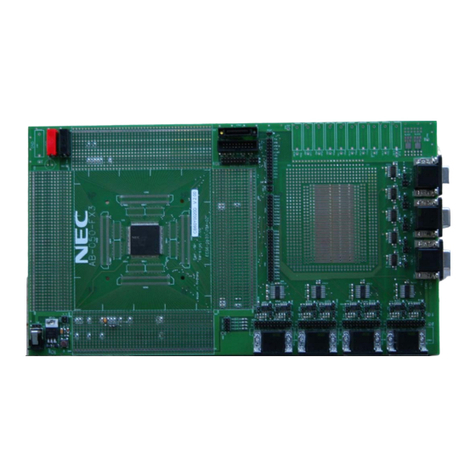
To facilitate design with an NEC Electronics flash microcontroller, a specific device, along
with appropriate crystals and reset circuitry is provided on a printed circuit board. All of the
package pins are brought out to standard 0.1-inch headers that surround the microcontroller
package on all four sides.
The K0RE81 board employs the µPD78F9882 flash microcontroller, which is identical to the
µPD789881 mask ROM version, except that it does not exhibit the same ultra-low-power
performance. A design therefore would be implemented in the K0RE81 board via the
µPD78F9882, and the code and operation thoroughly debugged before committing to mask
ROM release.
Table 1. µPD789881/ µPD78F9882 Comparison
µPD789881 µPD78F9882
Ultra-low power operation, I
DD4
<0.9 µa typ. Ultra-low-power operation not available
16 KB mask ROM 32 KB flash memory
26 x 4 LCD controller 26 x 4 LCD controller
Four timer channels Four timer channels
One serial UART channel One serial UART channel
28 I/O ports (four N-channel open drain) 28 I/O ports (four N-channel open drain)
Pull-up resistors on open-drain port (mask option) No pull-up resistors on open-drain port
On-chip multiplier: 8 x 8 = 16 bits On-chip multiplier: 8 x 8 = 16 bits
On-chip voltage divider and regulator On-chip voltage divider and regulator
5

K0RE81 Evaluation Platform for µPD78F9882
Figure 1. Board Layout
LCD Drive Capacitors
External DC
Supply Pads
Reset Circuitry
All package pins
brought out to
surrounding
headers on 0.1
centers
Reset Pushbutton
10-Pin
Flash Programming Header
and Serial Monitor Function
32 kHz Crystal
Sub-Oscillator
µPD78F9882
Table 2. K0RE81 (µPD78F9882) Pin Configuration
1 VLC2 17 P01 33 P11 49 S11
2 VLC1 18 P02 34 P10 50 S10
3 CAPH2 19 P03 35 P95/S25 51 S9
4 CAPL2 20 P50 36 P94/S24 52 S8
5 CAPL1 21 P51 37 P93/S23 53 S7
6 CAPH1 22 P52 38 P92/S22 54 S6
7 HV
DD
23 P53 39 P91/S21 55 S5
8 VR
OUT
24 V
SS0
40 P90/S20 56 S4
9 V
DD1
25 V
DD0
41 P84/S19 57 S3
10 V
SS1
26 P30/INTP0/TO0/T100 42 P83/S18 58 S2
11 XT1 27 P31/INTP1/TI51 43 P82/S17 59 S1
12 XT2 28 P32/INTP2/TO50/TI50 44 P81/S16 60 S0
13 ICO (V
PP
) 29 P33/INTP3/TI51 45 P80/S15 61 COM3
14 ICO (FPCLK) 30 P20/TO51 46 S14 62 COM2
15 /Reset 31 P21/TxD0 47 S13 63 COM1
16 P00
32 P22/RxD0 48 S12
64 COM0
Note: Package pin numbers match the header pinout numbers.
6

K0RE81 Evaluation Platform for µPD78F9882
2. CONNECTING TO THE K232 SERIAL ADAPTER
There are two ways to connect to the K232. The first is via the J2 10-pin stackable header.
Figure 2 shows the board’s orientation for stacking.
Figure 2. Stacked Connection
RS-232
Connector Stacking Socket
7

K0RE81 Evaluation Platform for µPD78F9882
The second is with an extension ribbon cable supplied with the K232 that plugs onto the P1
10-pin header on the circuit side of the K232. The other side plugs into the flash programmer
header on the K0RE81. These connections use keyed headers and can only be plugged in
one way. See Figure 3.
Figure 3. Ribbon Cable Connection
3. K232 JUMPER SETTINGS FOR THE K0RE81
1. Connect jumper JP1 if you want the K0RE81 to derive power from the K232 adapter.
2. Set jumper JP2 for 3.3-volt operation.
3. Set JP3 jumper on TX (pins 1–2)
4. Set JP4 jumper on RX (pins 2–3.
5. JP5 requires no jumper.
4. PRE-FLASHED FIRMWARE
The K0RE81 was flashed in manufacturing with the K0SM9882 mini-monitor program for
testing and diagnostics. The K232 will work with the K0RE81 right out of the box. Check the
K232 User’s Manual for communication port settings.
8

K0RE81 Evaluation Platform for µPD78F9882
Table 3. Bill of Materials
Item Part Name Description Value Digi-Key Part No. Quantity
1 R2 RES, SMT, 0805, 1.0k OHM, 5% 1.0k P1.0KACT-ND 5
2 R3 RES, SMT, 0805, 3.3k OHM,5 % 3.3k P3.3KACT-ND 1
3 R4 RES, SMT, 0805, 10k OHM, 5% 10k P10KACT-ND 3
4 R5 RES, SMT, 0805,100k OHM, 5% 100k P100KACT-ND 1
5 R1 RES, SMT, 0805, 220k OHM, 5% 220k P220KACT-ND 1
6 C5, C6, C7, C8, C9, C10 0.47µF, 25V, TAN CAP, TANT, SMT, 3216 0.47µF, 25V, 10% PCS5474CT-ND 6
7 C4 10uF, 16V, TAN CAP, TANT, SMT, 3528 10 µF, 16V, 10% PCS3106CT-ND 1
8 C1, C2 CAP, MLC, C0G, SMT, 0805, 33 pF, 50V, 5% 33 pF PCC330CGCT-ND 2
9 C3 CAP, MLC, C0G, SMT, 0805, 470 pF, 50V, 5% 470 pF PCC471CGCT-ND 1
10 C11 CAP, MLC, X7R, SMT, 1206, 100 nF, 50V, 10% 100 nF PCC104BCT-ND 1
11 X1 XTAL, 32 kHz, 8.2 mm, ECS-3X8 32 kHz X801-ND 1
12 U2 IC, LIN, VOLTAGE DETECTOR, 2.7V (SOT-23) TC54VN2702 TC54V2702ECB71CT 1
13 U1 IC, MCU, SMT, FLASH, NEC µPD78F9882 µPD78F9882 Available from NEC 1
14 P1 HDR, TWO-ROW, VERT, SHRD, 0.100", 10-Pin HDR, 10-Pin A26267-ND 1
15 S1 SWITCH, PUSHBUTTON, SPST, 6 mm x 3.5 mm,
SMT SW, EVQPP P8086SCT-ND 1
16 P2 HDR, TWO-ROW, VERT, SHRD, 0.100", 10-Pin HDR, 10-PIN A26267-ND 1
17 J1, J2, J3, J4 SKT, 16-Pin N/A (4)
18 T1, T2 Terminal TERM N/A 2
23 PCB Printed Circuit Board PCB N/A 1
9

K0RE81 Evaluation Platform for µPD78F9882
These commodities, technology or software, must be exported from the U.S. in accordance
with the export administration regulations. Diversion contrary to U.S. law prohibited.
The information in this document is current as of April 2003. The information is subject to change without notice. For
actual design-in, refer to the latest publications of NEC Electronics data sheets or data books, etc., for the most up-to-date
specifications of NEC Electronics products. Not all products and/or types are available in every country. Please check with an NEC
sales representative for availability and additional information.
No part of this document may be copied or reproduced in any form or by any means without prior written consent of NEC
Electronics. NEC Electronics assumes no responsibility for any errors that may appear in this document.
NEC Electronics does not assume any liability for infringement of patents, copyrights or other intellectual property rights of third
parties by or arising from the use of NEC Electronics products listed in this document or any other liability arising from the use of
such NEC Electronics products. No license, express, implied or otherwise, is granted under any patents, copyrights or other
intellectual property rights of NEC Electronics or others.
Descriptions of circuits, software and other related information in this document are provided for illustrative purposes in
semiconductor product operation and application examples. The incorporation of these circuits, software and information in the
design of customer's equipment shall be done under the full responsibility of customer. NEC Electronics no responsibility for any
losses incurred by customers or third parties arising from the use of these circuits, software and information.
While NEC Electronics endeavors to enhance the quality, reliability and safety of NEC Electronics products, customers
agree and acknowledge that the possibility of defects thereof cannot be eliminated entirely. To minimize risks of damage to property
or injury (including death) to persons arising from defects in NEC Electronics products, customers must incorporate sufficient safety
measures in their design, such as redundancy, fire-containment and anti-failure features.
NEC Electronics products are classified into the following three quality grades: “Standard”, “Special” and “Specific”.
The "Specific" quality grade applies only to NEC Electronics products developed based on a customer-designated “quality
assurance program” for a specific application. The recommended applications of NEC Electronics product depend on its quality
grade, as indicated below. Customers must check the quality grade of each NEC Electronics product before using it in a particular
application.
"Standard": Computers, office equipment, communications equipment, test and measurement equipment, audio and visual
equipment, home electronic appliances, machine tools, personal electronic equipment and industrial robots.
"Special": Transportation equipment (automobiles, trains, ships, etc.), traffic control systems, anti-disaster systems, anti-
crime systems, safety equipment and medical equipment (not specifically designed for life support).
"Specific": Aircraft, aerospace equipment, submersible repeaters, nuclear reactor control systems, life support systems
and medical equipment for life support, etc.
The quality grade of NEC Electronics products is “Standard” unless otherwise expressly specified in NEC Electronics data
sheets or data books, etc. If customers wish to use NEC Electronics products in applications not intended by NEC Electronics, they
must contact NEC Electronics sales representative in advance to determine NEC Electronics 's willingness to support a given
application.
(Notes)
(1) " NEC Electronics" as used in this statement means NEC Electronics Corporation and also includes its majority-owned
subsidiaries.
(2) " NEC Electronics products" means any product developed or manufactured by or for NEC Electronics (as defined above).
10
Table of contents
Other NEC Motherboard manuals

NEC
NEC POWERMATE ES Series User manual

NEC
NEC PowerMate CT User manual

NEC
NEC 78K0R/L 3 Sense it! Series User manual

NEC
NEC 78K0R - Save It! User manual

NEC
NEC PG-FPL3 User manual

NEC
NEC AB-050-FX3-U User manual

NEC
NEC MultiSync X462HB User manual

NEC
NEC PG-FP4 User manual

NEC
NEC EV-K0-HCD Instructions for use

NEC
NEC IE-78K0-NS-P04 User manual