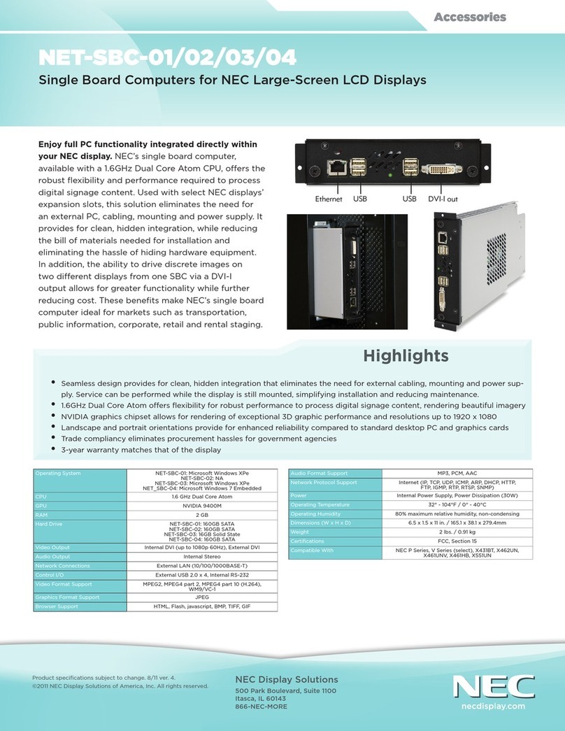
NEC AB-050-FX3-U User manual

User’s Manual
AB-050-FX3-U
V850ES/Fx3 Starter Board
Hardware
Document No. EASE-UM-0019-2.1
Date Published February 2007
© NEC Electronics 2007

NEC Electronics (Europe) GmbH
- 2 -
DISCLAIMER
•The information in this document is current as of April 2006. The information is subject to
change without notice. For actual design-in, refer to the latest publications of NEC
Electronics data sheets or data books, etc., for the most up-to-date specifications of NEC
Electronics products. Not all products and/or types are available in every country. Please
check with an NEC sales representative for availability and additional information.
•No part of this document may be copied or reproduced in any form or by any means without
prior written consent of NEC Electronics. NEC Electronics assumes no responsibility for any
errors that may appear in this document.
•NEC Electronics does not assume any liability for infringement of patents, copyrights or other
intellectual property rights of third parties by or arising from the use of NEC Electronics
products listed in this document or any other liability arising from the use of such NEC
Electronics products. No license, express, implied or otherwise, is granted under any patents,
copyrights or other intellectual property rights of NEC Electronics or others.
•Descriptions of circuits, software and other related information in this document are provided
for illustrative purposes in semiconductor product operation and application examples. The
incorporation of these circuits, software and information in the design of customer's
equipment shall be done under the full responsibility of customer. NEC Electronics assumes
no responsibility for any losses incurred by customers or third parties arising from the use of
these circuits, software and information.
•While NEC Electronics endeavours to enhance the quality, reliability and safety of NEC
Electronics products, customers agree and acknowledge that the possibility of defects
thereof cannot be eliminated entirely. To minimize risks of damage to property or injury
(including death) to persons arising from defects in NEC Electronics products, customers
must incorporate sufficient safety measures in their design, such as redundancy, fire
containment and anti-failure features.
•NEC Electronics products are classified into the following three quality grades: “Standard”,
“Special” and “Specific”. The "Specific" quality grade applies only to NEC Electronics
products developed based on a customer-designated “quality assurance program” for a
specific application. The recommended applications of NEC Electronics product depend on
its quality grade, as indicated below. Customers must check the quality grade of each NEC
Electronics product before using it in a particular application.
"Standard": Computers, office equipment, communications equipment, test and
measurement equipment, audio and visual equipment, home electronic
appliances, machine tools, personal electronic equipment and
industrial robots.
"Special": "Special": Transportation equipment (automobiles, trains, ships, etc.), traffic
control systems, anti-disaster systems, anti-crime systems, safety equipment
and medical equipment (not specifically designed for life support).
"Specific": "Specific": Aircraft, aerospace equipment, submersible repeaters, nuclear
reactor control systems, life support systems and medical equipment for life
support, etc.
The quality grade of NEC Electronics products is “Standard” unless otherwise expressly
specified in NEC Electronics data sheets or data books, etc. If customers wish to use NEC
Electronics products in applications not intended by NEC Electronics, they must contact
NEC Electronics sales representative in advance to determine NEC Electronics 's
willingness to support a given application.
Note: 1. "NEC Electronics" as used in this statement means NEC Electronics Corporation
and also includes its majority-owned subsidiaries.
2. "NEC Electronics products" means any product developed or
manufactured by or for NEC Electronics (as defined above).


NEC Electronics (Europe) GmbH
- 3 -
Table of Contents
1Introduction............................................................................................................................................................6
2Board description...................................................................................................................................................7
2.1 Overview..........................................................................................................................................................7
2.1.1 Electrical Area.........................................................................................................................................7
2.1.2 Functional Area.......................................................................................................................................8
2.1.3 Connecting both areas............................................................................................................................8
2.2 Reset................................................................................................................................................................9
2.3 NWire connection ............................................................................................................................................9
2.4 PG-FP4 connection .........................................................................................................................................9
2.5 RS-232 / LIN..................................................................................................................................................10
2.6 CAN ...............................................................................................................................................................13
3Mounting the FK3 device on the board ...............................................................................................................14
4Connecting the Power Supply.............................................................................................................................15
5UART / LIN CAN DSUB connectors....................................................................................................................16
5.1 UART / LIN connectors..................................................................................................................................16
5.2 CAN connectors.............................................................................................................................................17
6Mounting other Fx3 devices on the board...........................................................................................................18
6.1 Mounting devices...........................................................................................................................................18
6.1.1 Mounting a FE3 device.........................................................................................................................18
6.1.2 Mounting a FF3 device..........................................................................................................................19
6.1.3 Mounting a FG3 device.........................................................................................................................19
6.1.4 Mounting a FJ3 device..........................................................................................................................20
6.2 Pin connection ...............................................................................................................................................21
6.2.1 Power supply pins.................................................................................................................................21
6.2.2 REGC pin..............................................................................................................................................22
6.2.3 X1, X2 pins............................................................................................................................................23
6.2.4 XT1, FLMD0..........................................................................................................................................24
6.3 Functional pin connection..............................................................................................................................25
6.3.1 Jumper overview...................................................................................................................................25
6.3.2 Testpoints..............................................................................................................................................26
6.3.3 Reset signal ..........................................................................................................................................26
6.3.4 NWIRE signals......................................................................................................................................27
6.3.5 Flash Programming interface................................................................................................................27
6.3.6 CAN interface........................................................................................................................................28
6.3.7 UARTD interface...................................................................................................................................29
7Revision History...................................................................................................................................................30
8Appendix A – Pin Number templates ..................................................................................................................31
9Appendix B - Schematic......................................................................................................................................32

NEC Electronics (Europe) GmbH
- 4 -
List of Figures
Figure 1 AB-050-FX3-U with FK3 Device.....................................................................................................................6
Figure 2-1 Board overview .......................................................................................................................................7
Figure 2-2 Pin Patch Area........................................................................................................................................8
Figure 3-1 FK3 device mounting (1).......................................................................................................................14
Figure 3-2 FK3 device mounting (2).......................................................................................................................14
Figure 5-1 UART / LIN DSUB connectors..............................................................................................................16
Figure 5-2 CAN DSUB connector...........................................................................................................................17
Figure 6-1 Mounting a FE3 device.........................................................................................................................18
Figure 6-2 Mounting a FF3 device..........................................................................................................................19
Figure 6-3 Mounting a FG3 device.........................................................................................................................19
Figure 6-4 Mounting a FJ3 device..........................................................................................................................20
Figure 6-5 Device power supply.............................................................................................................................21
Figure 6-6 REGC pin components .........................................................................................................................22
Figure 6-7 X1, X2 pin components.........................................................................................................................23
Figure 6-8 Pins with Pull-Down ..............................................................................................................................24
Figure 6-9 Jumpers location...................................................................................................................................25
Figure 6-10 Test Point location............................................................................................................................26

NEC Electronics (Europe) GmbH
- 5 -
List of Tables
Table 2-1 Overview of functional signals ................................................................................................................8
Table 2-2 CN48 – Nwire..........................................................................................................................................9
Table 2-3 FP4 (CSI) Jumpers .................................................................................................................................9
Table 2-4 FP4 (UART) Jumpers............................................................................................................................10
Table 2-5 UARTDn signal jumpers .......................................................................................................................10
Table 2-6 RS-232 signal jumpers..........................................................................................................................11
Table 2-7 LIN bus signal jumpers..........................................................................................................................12
Table 2-8 CAN signal jumpers ..............................................................................................................................13
Table 5-1 UART / LIN DSUB connectors..............................................................................................................16
Table 5-2 CAN DSUB connectors.........................................................................................................................17
Table 6-1 VSS signal connection..........................................................................................................................21
Table 6-2 VDD signal connection..........................................................................................................................22
Table 6-3 REGC signal connection.......................................................................................................................22
Table 6-4 X1, X2 signal connection ......................................................................................................................23
Table 6-5 XT1, FLMD0 signal connection.............................................................................................................24
Table 6-6 Colours of Jumper functionality.............................................................................................................26
Table 6-7 Reset signal connection........................................................................................................................26
Table 6-8 NWire interface signals.........................................................................................................................27
Table 6-9 Flash programming jumper settings......................................................................................................27
Table 6-10 CAN jumper settings.............................................................................................................................28
Table 6-11 UARTD jumper settings........................................................................................................................29

NEC Electronics (Europe) GmbH
- 6 -
1 Introduction
The AB-050-FX3-U is designed as a simple and easy to use Starter Board to support users with the first steps
when starting with the Fx3-Series family.
The Starter Board is prepared to hold a V850ES/FK3 device (uPD70F3385). As the largest device of the Fx3-
Series the FK3 offers the complete range of all Fx3 peripherals. Therefore software development for all other Fx3-
Series devices is possible as well. Due to the software compatibility between the different family members porting
of SW from FK3 to smaller devices is possible with only minimum efforts.
Mounting other members of the Fx3-Series on the board also is possible, at the cost of manual replacement of
components and rewiring of signals.
With the NWire Debug interface and the Flash Programming interface for the NEC PG-FP4 Flash Programmer the
standard NEC programming interfaces are directly available.
To enable further application development the board features drivers for five high speed CAN interfaces, eight RS-
232 interfaces and eight LIN bus interfaces.
With on-board voltage regulator and reset generator a simple external DC power supply is sufficient to operate the
board.
Figure 1 AB-050-FX3-U with FK3 Device

NEC Electronics (Europe) GmbH
- 7 -
2 Board description
2.1 Overview
Pin Patch Area
Pin Patch Area
Pin Patch Area
Pin Patch Area
CN0
CN63
CN2
CN28
CN1
CN6
CN7
CN8
CN10
CN5
CN4
CN3
CN11
CN12
CN13
CN15
CN14
CN31
CN29
CN30
CN32
JP11
JP15
CN49
JP1 CN52
JP2
1
2
JP26
JP27
JP28
JP29
JP7
CN47
CN46
CN45
CN44
2
1
2
1
2
1
2
1
CN53
TP1
TP15
TP50
TP11
TP12
TP48
TP54
TP56
TP58
TP62
TP60
TP7
TP6
CN18CN17CN37
CN20 CN19CN22 CN21CN34 CN33CN36 CN35
JP12JP10
JP13
JP16JP14
JP17
JP20JP18
JP21
JP24JP22
JP25
JP36JP33
JP37
JP40JP38
JP41
CN38CN39CN40
CN23
CN48
12
21
CN24
2
1
CN9
2
1
JP22
CN16
JP3
JP3JP5
JP4
JP8JP6
JP9
TP5 TP4
CN54
CN55 CN56
CN59 CN60
CN57 CN58
Figure 2-1 Board overview
Basically the board is divided into two areas, an ‘Electrical Area’ and a ‘Functional Area’.
In Figure 2-1 the Electrical Area is surrounded in by a red line and the Functional Area is surrounded by a blue line.
2.1.1 Electrical Area
In the center of the Electrical Area a 180 pin SMD pad field is located that any of the F-Series devices can be
assembled to.
On each side of the Device Pad Field a Pin Patch Area is located. In this patch area access is given to
- each pin of the device
- VDD
- VSS
Further more SMD and through hole components can directly be soldered onto the Pin Patch Area to allow simple
networks to be easily built up.
The circuitry available at each pin inside the Pin Patch Area is described in the figure below:

NEC Electronics (Europe) GmbH
- 8 -
VDD
VSS
SMD1
SMD2
Device
signal
Figure 2-2 Pin Patch Area
A component assembled to the SMD1 field will therefore be connected between the device pin and VSS.
A component assembled to the SMD2 field will be connected between the device pin and VCC.
2.1.2 Functional Area
The Functional Area holds the drivers for RS-232, LIN bus and CAN. Additionally other patch areas are available
as well to directly assemble LEDs, PowerDrivers and connectors to the board.
Note:
For detailed information about the operation of the used RS-232, LIN bus and CAN drivers refer to the related
datasheets of those devices.
2.1.3 Connecting both areas
The Electrical and Functional Areas are not connected to one another except by a common VSS plane.
Nevertheless by use of Jumpers a signal connection between the Electrical Area and the Functional Area is
possible.
The following signals are available on the related jumper fields:
Signal Jumper
_Reset CN52
VDD CN49
Flash programming (PG-FP4) CN48
JP2
NWIRE CN48
UARTDn (n=0..7) CN9
CANn (n=0..4) CN24
Table 2-1 Overview of functional signals

NEC Electronics (Europe) GmbH
- 9 -
2.2 Reset
A simple Reset Generator using analog circuitry is available.
To connect the on-board Reset generator to the FK3 device close CN52 3-4.
If an external Reset signal shall be connected to the board the following setup must be used:
a) Use TP15 to physically connect the external reset signal.
b) Close CN52 1-2 to connect the external reset signal to the FK3 device.
c) Open CN52 3-4 to disconnect the onboard Reset circuitry from the device.
2.3 NWire connection
The NWire debug cable from a NEC Debug Tool (e.g. MiniCube) can be connected to CN2.
Additionally a KEL connector (CN23) is available to connect third party NWire Debug Tools.
The following jumpers on CN48 must be closed in order to physically connect the NWire signals from CN2 to the
corresponding pins of the FK3 device:
Signal CN48 Pin number
SCK 9 – 10
DCK 11 – 12
DMS 13 – 14
DDI 15 – 16
DRST 17 – 18
RES 19 – 20
FLMD0 21 – 22
DDO 23 – 24
Table 2-2 CN48 – Nwire
Additionally JP2 must be closed.
2.4 PG-FP4 connection
The programming cable of the PG-FP4 Flash programmer can be connected to CN28.
To program the device via the CSI interface the following jumpers must be closed:
Connector Pin number
JP15 2 – 3
JP11 2 – 3
CN48 5 – 6
7 – 8
Table 2-3 FP4 (CSI) Jumpers

NEC Electronics (Europe) GmbH
- 10 -
To program the device via the UART interface the following jumpers must be closed:
Connector Pin number
JP15 1 – 2
JP11 1 – 2
CN48 1 – 2
3 – 4
Table 2-4 FP4 (UART) Jumpers
For Flash programming using the PG-FP4 device power can either be supplied by the PG-FP4 or by the AB-050-
FX3.
a) For PG-FP4 power supply open JP2.
b) For AB-050-FJ3 power supply close JP2.
If the clock supply for PG-FP4 programming is not on board, close CN48 Pins 25-26 to supply the clock from PG-
FP4.
2.5 RS-232 / LIN
Close CN49 1 – 2 and 3 – 4 to supply power to RS-232 / LIN bus drivers.
For the LIN bus drivers additionally a VBAT voltage must be supplied. This voltage must be in a range of 5V to 12V.
For the exact specification refer to the Datasheet of the LIN Drivers.
To supply VBAT to the board use either of the two connections:
- Use TP1
- Close JP19 and use Cn16
Close the following jumpers on CN9 to physically connect the UARTD signals from the Electrical Area to the
Functional Area.
Signal CN9 Pin #
TXD0 1 – 2
UARTD0 RXD0 3 – 4
TXD1 5 – 6
UARTD1 RXD1 7 – 8
TXD2 9 – 10
UARTD2 RXD2 11 – 12
TXD3 13 – 14
UARTD3 RXD3 15 – 16
TXD4 17 – 18
UARTD4 RXD4 19 – 20
TXD5 21 – 22
UARTD5 RXD5 23 – 24
TXD6 25 – 26
UARTD7 RXD6 27 – 28
TXD7 29 – 30
UARTD6 RXD7 31 – 32
Table 2-5 UARTDn signal jumpers

NEC Electronics (Europe) GmbH
- 11 -
To connect the RS-232 / LIN bus driver signals to the RS-232 / LIN bus connecters close the following jumpers:
Signal Connector Pin #
TXD0 1 – 2
RXD0 3 – 4
UARTD0 GND CN19 5 – 6
TXD1 1 – 2
RXD1 3 – 4
UARTD1 GND CN20 5 – 6
TXD2 1 – 2
RXD2 3 – 4
UARTD2 GND CN21 5 – 6
TXD3 1 – 2
RXD3 3 – 4
UARTD3 GND CN22 5 – 6
TXD4 1 – 2
RXD4 3 – 4
UARTD4 GND CN33 5 – 6
TXD5 1 – 2
RXD5 3 – 4
UARTD5 GND CN34 5 – 6
TXD6 1 – 2
RXD6 3 – 4
UARTD6 GND CN35 5 – 6
TXD7 1 – 2
RXD7 3 – 4
UARTD7 GND CN36 5 – 6
Table 2-6 RS-232 signal jumpers

NEC Electronics (Europe) GmbH
- 12 -
To connect the LIN bus driver signals to the related RS-232/LIN bus connector close the following jumpers:
Signal Connector Pin #
12V 7 – 8
LIN 9 – 10
LIN0 GND CN19 11 – 12
12V 7 – 8
LIN 9 – 10
LIN1 GND
CN20 11 – 12
12V 7 – 8
LIN 9 – 10
LIN2 GND CN21 11 – 12
12V 7 – 8
LIN 9 – 10
LIN3 GND CN22 11 – 12
12V 7 – 8
LIN 9 – 10
LIN4 GND CN33 11 – 12
12V 7 – 8
LIN 9 – 10
LIN5 GND
CN34 11 – 12
12V 7 – 8
LIN 9 – 10
LIN6 GND CN35 11 – 12
12V 7 – 8
LIN 9 – 10
LIN7 GND CN36 11 – 12
Table 2-7 LIN bus signal jumpers
To enable the LIN drivers (IC218, IC219, IC172, IC221, IC217, IC223, IC228, IC229) the NSLP pin of the drivers
must be pulled high. To do so a Jumper is available to connect the pin to VDD.
LIN channel NSLP Jumper
0 JP3
1 JP8
2 JP12
3 JP16
4 JP20
5 JP24
6 JP40
7 JP36

NEC Electronics (Europe) GmbH
- 13 -
The RxD pin of the LIN driver (pin #1) is an open drain output. The necessary pull-up resistor in order to interface
to the Fx3 device is not assembled on the board. To enable operation of the RxD signal
- either connect an appropriate pull up resister to the related RxD input pin of the LIN channel, or
- enable the internal Pull-Up resistors available in the Fx3 devices for each LIN input pin.
The corresponding input pin for each RxD pin can be found in Table 6-11.
For additional information on the LIN driver refer to its User’s Manual / Datasheet.
Caution: The RXD reception output pin of the LIN driver (e.g. IC218 pin1) and the RxD reception output pin of
the UART driver (e.g. IC173 pin 12) are physically connected to the same pin on connector CN9 (e.g.
CN9 pin 4).
Therefore
- when using the LIN driver lift the connected UART driver RxD output pin from the PCB.
- when using the UART driver place the connected LIN driver in standby mode or lift the LIN
driver RxD output pin from the board.
2.6 CAN
Close CN49 1 – 2 and 3 – 4 to supply power to the CAN drivers.
Close the following jumpers to physically connect the devices CAN signals to the CAN interface drivers located on
the Functional Area of the board:
Signal CN24 Pin #
CTXD0 1 – 2
CAN0 CRXD0 3 – 4
CTXD1 5 – 6
CAN1 CRXD1 7 – 8
CTXD2 9 – 10
CAN2 CRXD2 11 – 12
CTXD3 13 – 14
CAN3 CRXD3 15 – 16
Table 2-8 CAN signal jumpers

NEC Electronics (Europe) GmbH
- 14 -
3 Mounting the FK3 device on the board
The AB-050-FX3-U boards is shipped with a mounted V850ES/FK3 device.
Nevertheless, if mounting of another V850ES/FK3 device is required at a later time the following guideline is
supplied:
To mount a FK3 device on the AB-050-FX3-U place the package in the top right corner of the SMD area.
As the FK3 with 176 pins is placed on an SMD area with 180 pins 4 pads will not be used. Due to the alignment of
the device in the top right corner two pads in the lowest line and two pads in the left most line remain empty.
Therefore align pin 1 of the device with pin 2 of the SMD pad area.
For details see Figure 3-1 and Figure 3-2.
Figure 3-1 FK3 device mounting (1)
CN0
CN31
CN29
CN30
CN32
FK3
1
Figure 3-2 FK3 device mounting (2)

NEC Electronics (Europe) GmbH
- 15 -
4 Connecting the Power Supply
Power can be supplied to the board either
a) by directly supplying the device operating voltage, or
b) via the onboard 7805 type voltage regulator.
Direct voltage supply:
A direct supply of the device operating voltage can either be implied by using CN7 to connect VCC (typical +5V for
Fx3 devices) and CN8 to connect VSS (0V), or by using CN1.
As the supplied voltage is directly connected to the device the input voltage must not exceed the specified power
supply voltage range of the assembled device.
Close JP1 1-2 when directly supplying the devices voltage.
Voltage regulator supply:
Use CN1 to supply a stabilized voltage of 6V - 12V to the board. The on board 7805 type regulator will generate the
5V supply of the board.
Close JP1 2-3 when using the on board voltage regulator.
Caution: On CN1 the inner pin connects to VSS and the outer pin connects to VCC.
Applying a voltage to the device outside the specified device operating voltage range may damage
the device!

NEC Electronics (Europe) GmbH
- 16 -
5 UART / LIN CAN DSUB connectors
To physically connect the Starter Board to other UART / LIN / CAN devices DSUB type connectors are available..
5.1 UART / LIN connectors
To interface the AB-050-FX3-U board to external to UART / LIN devices a 9 pin male D-SUB connector is supplied
for each of the eight available UART / LIN interfaces.
The signal layout of the UART/LIN DSUB connector can be seen in Table 5-1.
Male D-SUB,
9pin Function
1 n/c
6 n/c
2 RS-232 TxD
7 LIN
3 RS-232 Rxd or GND
8 n/c
4 n/c
9 +12V
5 GND
Table 5-1 UART / LIN DSUB connectors
Figure 5-1 displays the assignment of each DSUB connector to its related peripheral:
UART0
UART1
UART2
UART3
UART4
UART5
UART6
UART7
Figure 5-1 UART / LIN DSUB connectors

NEC Electronics (Europe) GmbH
- 17 -
5.2 CAN connectors
To interface the AB-050-FX3-U board to external CAN devices a 9 pin female D-SUB connector is supplied for
each of the five available CAN interfaces.
The pin functions of the CAN DSUB connectors can be seen in Table 5-2.
Female D-SUB,
9pin Function
1 n/c
6 GND
2 CANL
7 CANH
3 GND (if jumpered)
8 n/c
4 n/c
9 n/c
5 n/c
Table 5-2 CAN DSUB connectors
Figure 5-2 displays the assignment of each DSUB connector to its related peripheral:
CAN0
CAN1
CAN2
CAN3
CAN4
Figure 5-2 CAN DSUB connector

NEC Electronics (Europe) GmbH
- 18 -
6 Mounting other Fx3 devices on the board
Even though the AB-050-FX3-U is prepared for operation of the FK3 device also other devices of the Fx3-Line can
be mounted on the board.
Besides mounting the new device to the board
- the components in the Pin Patch Area must be replaced according to the pin layout of the new device and
- the signals between the device pins and the jumpers connecting the Electrical Area and the Functional
Area must wired manually.
Therefore the following changes must be applied:
6.1 Mounting devices
First the device must be mounted to the PCB. The alignment of the different Fx3-family devices is explained below.
6.1.1 Mounting a FE3 device
To mount a FE3 device on the AB-050-FX3-U place the package in the lower left corner of the SMD area but do
not use the two pins most in the corner. Place pin 1 of the device on pin 2 of the SMD area.
CN31
CN29
CN30
CN32
FE3
1
Figure 6-1 Mounting a FE3 device

NEC Electronics (Europe) GmbH
- 19 -
6.1.2 Mounting a FF3 device
To mount a FF3 device on the AB-050-FX3-U place the package in the lower left corner of the SMD area but do not
use the two pins most in the corner. Place pin 1 of the device on pin 2 of the SMD area.
CN31
CN29
CN30
CN32
FF3
1
Figure 6-2 Mounting a FF3 device
6.1.3 Mounting a FG3 device
To mount a FF3 device on the AB-050-FX3-U place the package in the lower left corner of the SMD area. Place pin
1 of the device on pin 1 of the SMD area.
CN31
CN29
CN30
CN32
FG3
1
Figure 6-3 Mounting a FG3 device

NEC Electronics (Europe) GmbH
- 20 -
6.1.4 Mounting a FJ3 device
To mount a FJ3 device on the AB-050-FX3-U place the package in the lower left corner of the SMD area. Place pin
1 of the device on pin 1 of the SMD area.
CN31
CN29
CN30
CN32
FJ3
1
Figure 6-4 Mounting a FJ3 device
Table of contents
Other NEC Motherboard manuals

NEC
NEC PG-FPL2 User manual

NEC
NEC QB-MINI2-EE User manual

NEC
NEC PG-FPL User manual

NEC
NEC 78K0R - Save It! User manual

NEC
NEC PG-FP4 User manual

NEC
NEC 78K0R - Save It! User manual

NEC
NEC uPD168804 User manual

NEC
NEC PG-FPL3 User manual

NEC
NEC IE-78K0-NS-P04 User manual

NEC
NEC POWERMATE ES Series User manual

NEC
NEC PowerMate CT User manual

NEC
NEC IE-703081-MC-EM1 User manual

NEC
NEC 78K0R/L 3 Sense it! Series User manual

NEC
NEC K0RE81 User manual

NEC
NEC PowerMate ES SlimLine Series Quick guide

NEC
NEC MultiSync X551UN User manual

NEC
NEC MultiSync X462HB User manual

NEC
NEC MultiSync P521 User manual

NEC
NEC EV-K0-HCD Instructions for use