NEC DLP Cinema NP-NC1402L User manual

User’s Manual
DLP Cinema®Projector
NP-NC1402L
NP-NC1202L
Model No.
NP-NC1402L / NP-NC1202L

2
Important Information
Precautions: Please read this manual carefully before
using your NP-NC1402L / NP-NC1202L and keep the man-
ual handy for future reference.
The NP-NC1402L / NP-NC1202L is called the “projector”,
and the IMB (integrated media server) is called the “media
block” or “IMB” in this manual.
• DLP (Digital Light Processing), DLP Cinema and DLP
Cinema logo are trademarks of Texas Instruments.
• Microsoft, Windows and Internet Explorer are either reg-
istered trademarks or trademarks of Microsoft Corporation
in the United States and/or other countries.
• Mozilla and Firefox are either registered trademarks or
trademarks of the Mozilla Foundation in the United States
and/or other countries.
• Oracle and Java are registered trademarks of Oracle
and/or its affiliates.
• Linux is a registered trademark of Linus Torvalds in the
United States and/or other countries.
• Other product names and logos mentioned in the user’s
manual may be the trademarks or registered trademarks
of their respective holders.
• The display screens and illustrations shown in this man-
ual may differ slightly from the actual ones.
• GPL/LGPL Software Licenses
• The product includes software licensed under GNU
• General Public License (GPL), GNU Lesser General
Public License (LGPL), and others.
• For more information on each software, see “readme.pdf”
inside the “about GPL&LGPL” folder on the supplied
CD-ROM.
WARNING
TO REDUCE THE RISK OF FIRE OR ELECTRIC SHOCK,
DO NOT EXPOSE THIS APPLIANCE TO RAIN OR
MOISTURE.
CAUTION
TO PREVENT ELECTRIC SHOCK, DO NOT OPEN TOP
COVER. NO USER SERVICEABLE PARTS INSIDE.
This symbol warns the user that uninsulated
voltage within the unit may have sufficient
magnitude to cause electric shock.
Therefore, it is dangerous to make any kind
of contact with any part inside of this unit.
This symbol alerts the user that important
literature concerning the operation and
maintenance of this unit has been included.
Therefore, it should be read carefully in order
to avoid any problems.
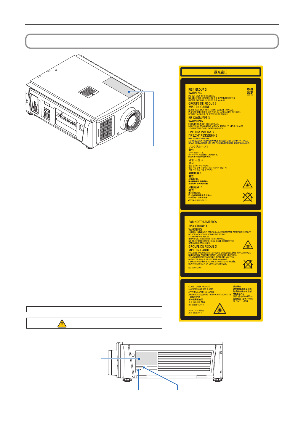
Laser Safety Caution
This product is classied as Class 1 of IEC 60825-1 Third
edition 2014. This product is classied as RG3 of IEC/EN
62471-5 First edition 2015.
This product is classied as RG3 of IEC 62471:2006.(for
USA). Obey the laws and regulations of your country in rela-
tion to the installation and management of the device.
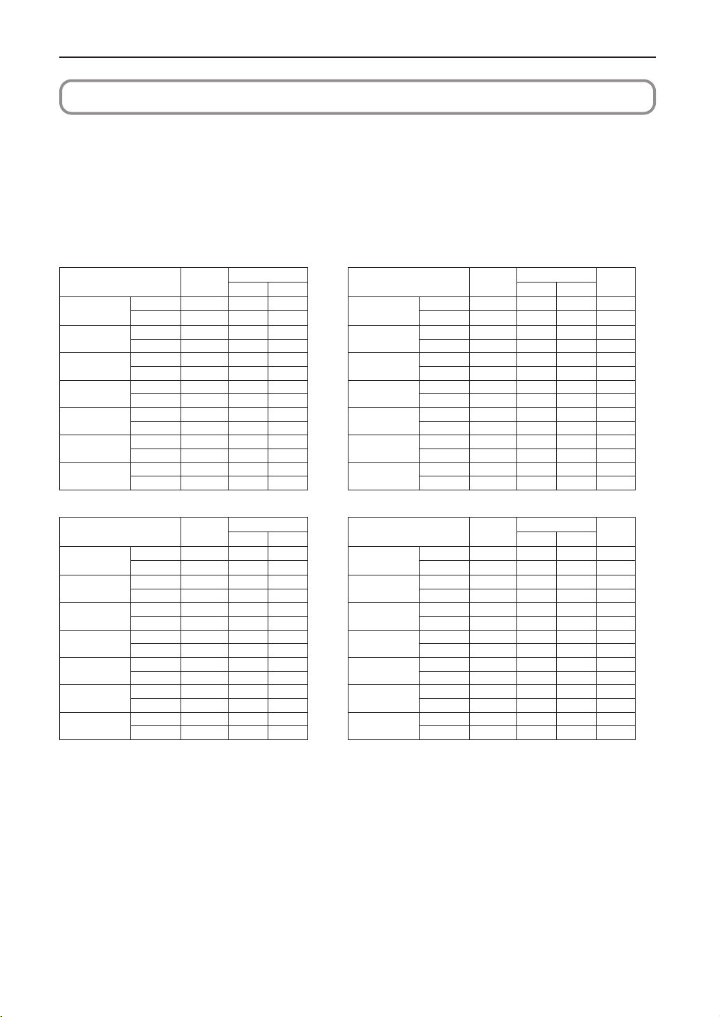
• Outlineoflaseremittedfromthebuilt-inlightmodule
Wave length: Blue 450–470 nm
Maximum power: Blue 563 W
• Radiationpatternfromtheprotectivehousing
Wave length: Blue 450-470 nm
Maximum laser radiation output: Blue 750 mW
CAUTION
Use of controls or adjustments of procedures other than
those specied herein may lead to hazardous laser radi-
ation exposure.
• Hazardous optical radiation is emitted from this product,
RG3 IEC 62471:2006. (for USA).
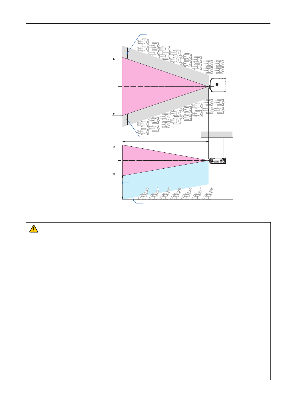
• No direct exposure to the beam shall be permitted, RG3
IEC/EN 62471-5:2015.
Operators shall control access to the beam within the
hazard distance or install the product at the height that
will prevent spectators’ eyes from being in the hazard
distance.
• Do not look into the lens while the projector is on. Serious
damage to your eyes could result.
• Do not look at operating light source. Eye injury may
result, RG3 IEC 62471:2006. (for USA)
• No direct exposure to beam shall be permitted, RG3 IEC
62471:2006. (for USA).
• Not for household use, RG3 IEC 62471:2006. (for USA)
• This projector must be installed high enough to provide
clearance for people who may walk beneath the beam
path or hazard distance, RG3 IEC 62471:2006. (for USA)
• Direct exposure of human eyes to beam is prohibited.
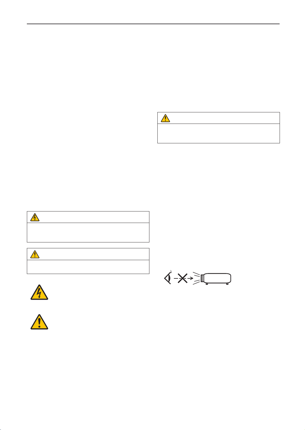
• The following graphic symbol indicating that looking into
the projector is prohibited is displayed on the projector
cabinet.
• Do not look at the projected light using optical devices
(magnifying glasses, reectors, etc.). Doing so could
result in vision impairment.
• When performing the lens shift adjustment, make sure
that you are behind or beside the projector. Doing so from
the front of the projector may cause intense light to enter
into your eyes, resulting in damage to them.
• This projector, which is an RG3 product, is for business
use and must be installed in location where safety is
assured. For this reason, installation of the projector and
mounting and removal of the lens unit must be performed
by professional service personnel. To do the works, be
sure to consult your dealer. NEVER install the projector
by end users. Doing so may cause visual impairment and
other injuries.
• Keep any items such as magnifying glass out of the light
path of the projector. The light being projected from the
lens is extensive, therefore any kind of abnormal objects
that can redirect light coming out of the lens, can cause
unpredictable outcome such as re or injury to the eyes.

3
Important Information
• When turning on the projector, ensure that nobody is fac-
ing towards the lens in the path of the light emitted from
the laser.
• This product can only be operated in theaters by speci-
ed personnel. Customers should not operate this
product.
WARNING
This equipment is compliant with Class A of CISPR 32.
In a residential environment this equipment may cause
radio interference.
FCC Information (for USA only)
WARNING
• The Federal Communications Commission does not allow
any modications or changes to the unit EXCEPT those
specied by Sharp NEC Display Solutions of America, Inc.
in this manual. Failure to comply with this government regu-
lation could void your right to operate this equipment.
• This equipment has been tested and found to comply with
the limits for a class A digital device, pursuant to Part 15 of
the FCC Rules. These limits are designed to provide rea-
sonable protection against harmful interference when the
equipment is operated in a commercial environment. This
equipment generates, uses, and can radiate radio fre-
quency energy and, if not installed and used in accordance
with the instruction manual, may cause harmful interfer-
ence to radio communications. Operation of this equipment
in a residential area is likely to cause harmful interference
in which case the user will be required to correct the inter-
ference at his own expense.
Supplier’s declaration of conformity
This device complies with Part 15 of FCC Rules. Operation
is subject to the following two conditions.
This device complies with Part 15 of FCC Rules.
Operation is subject to the following two conditions.
(1) This device may not cause harmful interference,
and (2) this device must accept any interference
received, including interference that may cause
undesired operation.
U.S.Responsible Party: Sharp NEC Display Solutions
of America, Inc.
Address: 3250 Lacey Rd, Ste 500
Downers Grove, IL 60515
Telephone Number: 630-467-3000
Type of Product: Projector
Equipment Classication: Class A Peripheral
Model Number: NP-NC1402L / NP-NC1202L
WARNING
THE END USER IS NOT ALLOWED TO OPEN OR
MODIFY THE PRODUCT.
NO USER SERVICEABLE PARTS.
MAINTAIN AND SERVICE OF THE PRODUCT IS ONLY
TO BE HANDLED BY NEC AUTHORIZED TECHNICIANS.
Important Safeguards
These safety instructions are to ensure the long life of your
projector and to prevent re and shock. Please read them
carefully and heed all warnings.
Installation
1. Do not point the projection beam toward other people or
reective objects.
2. Consult your dealer for information about transporting
and installing the projector. Do not attempt to transport
and install the projector yourself.
The projector must be installed by qualied technicians
in order to ensure proper operation and reduce the risk
of bodily injury.
3. Place the projector on a at, level surface in a dry area
away from dust and moisture. Tilting the front of the pro-
jector up or down from level could reduce laser life.
Do not put the projector on its side when the laser is on.
Doing so may cause damage to the projector.
4. Do not place the projector in direct sunlight, near heaters
or heat radiating appliances.
5. Exposure to direct sunlight, smoke or steam could harm
internal components.
6. Handle your projector carefully. Dropping or jarring your
projector could damage internal components.
7. When moving the projector, be sure to remove the lens
from the projector before moving it.
8. To carry the projector, a minimum of four persons are
required.
9. Do not hold the lens part with your hand. Otherwise the
projector may tumble or drop, causing personal injury.
10.Do not place heavy objects on top of the projector.
11. Turn off the projector, and disconnect the power cable
before moving the projector.
12.The cooling fan settings need to be congured when
using the projector in a location at an altitude of approxi-
mately 5500 feet/1600 meters or higher. Consult your
dealer in advance.
13.Turn off the projector when removing and installing
lenses. Failure to do so can cause loss of vision.
For mounting or replacing the lens, please contact your
dealer.
14.Do not install and store the projector in the below
circumstances.
Failure to do so may cause of malfunction.
• Inpowerfulmagneticelds
• Incorrosivegasenvironment
• Outdoors
15.If you wish to have the projector installed on the ceiling;
• Donotattempttoinstalltheprojectoryourself.
• Theprojectormustbeinstalledbyqualiedtechni-
cians in order to ensure proper operation and reduce
the risk of bodily injury.
• Inaddition,theceilingmustbestrongenoughtosup-
port the projector and the installation must be in
accordance with any local building codes.
• Pleaseconsultyourdealerformoreinformation.
16.When moving the projector, check the following:
• Thattheprojectoristurnedoff,thepowerplugisdis-
connected from the outlet
• Thattheconnectorcablethatconnectsthedeviceto
the projector is unplugged

4
Important Information
WARNING
1. Do not cover the lens with the supplied lens cap or
equivalent while the projector is on. Doing so can
lead to distorting or melting of the cap and burning
your hands due to the heat emitted from the light
output.
2. Do not place any objects, which are easily affected by
heat, in front of the projector lens. Doing so could
lead to the object melting from the heat that is emitted
from the light output.
When using the projector tilted in the forward or backward
direction, use it in the range of (+10° to -15°) from horizontal.
If you tilt it outside of this range or tilt it to the left or right, it
may become damaged.
If the projector is tilted outside of this range when used tilted
in the forward or backward direction, “TiltDegreeOver” is
displayed on the LCD screen. If this message appears,
change the installation of the projector so that the angle is
within the given range from horizontal.
+10°
–15°
When installed on a oor or a desktop
Power Supply
1. The projector is so designed that it operates with the
power supply voltage described below.
• Projector
AC200–240V single phase 50/60Hz
Ensure that your power supply ts this requirement
before attempting to use your projector.
2. The power cable is not included with the projector. Ask
your dealer for the power cable to select and purchase.
Use a power cable that meets the standards and power
supply voltage of the country where you are using the
projector.
Refer to “2-2. Connecting the Power Cable” (page 22)
for details on connecting the power cable.
3. Handle the power cable carefully. A damaged or frayed
power cable can cause electric shock or re.
• Donotbendortugthepowercableexcessively.
• Donotplacethepowercableundertheprojector,or
any heavy object.
• Donotcoverthepowercablewithothersoftmateri-
als such as rugs.
• Donotheatthepowercable.
• Donotchangethearrangementoftheinstalled
power cable.
4. If the projector will not be used for an extended period of
time, turn off the projector, and disconnect the power
plug from the outlet.
5. Placing the power cable and the signal cable closely to
each other can cause beat noise. If this happens, keep
the two separated so that beat noise is not generated.
Beat noise is corruption of the picture often seen as a
rolling band moving through the image.
6. Do not touch the projector during a thunder storm. Doing
so can cause electrical shock or re.
7. When installed on the ceiling, install the breaker in a
location that is easy to reach by hand.
Fire and Shock Precautions
1. Ensure that there is sufficient ventilation and that vents
are unobstructed to prevent potentially dangerous con-
centrations of ozone and the build-up of heat inside your
projector. Allow at least 19.7 inches (50cm) of space
between your projector and a wall. In particular, clear a
space of 27.6 inches (70 cm) or more in front of the air
outlet on the rear surface and 12 inches (30 cm) or more
on the upper part of the projecter body.
2. Prevent foreign objects such as paper clips and bits of
paper from falling into your projector. Do not attempt to
retrieve any objects that might fall into your projector. Do
not insert any metal objects such as a wire or screw-
driver into your projector. If something should fall into
your projector, turn off the projector, disconnect the
power plug from the outlet and have the object removed
by a qualied service person.
3. Turn off the projector, unplug the power cable and have
the projector serviced by a qualied service personnel
under the following conditions:
• Whenthepowercableorplugisdamagedorfrayed.
• Ifliquidhasbeenspilledintotheprojector,orifithas
been exposed to rain or water.
• Iftheprojectordoesnotoperatenormallywhenyou
follow the instructions described in this user’s
manual.
• Iftheprojectorhasbeendroppedorthecabinethas
been damaged.
• Iftheprojectorexhibitsadistinctchangeinperfor-
mance, indicating a need for service.
4.
Keep any items such as magnifying glass out of the light
path of the projector. The light being projected from the
lens is extensive, therefore any kind of abnormal objects
that can redirect light coming out of the lens, can cause
unpredictable outcome such as re or injury to the eyes.
5. Never remove or open the projector cabinet and never
modify the projector. Otherwise, re, electric shock, or
leakage of laser light may cause visual impairment or
burn injuries.
6. When using a LAN cable:
For safety, do not connect to the connector for peripheral
device wiring that might have excessive Voltage.

5
7. Do not try to touch the air outlets on the projector during
normal projector operation as it is hot.
Cleaning
1. Turn off the projector and unplug the power cable before
cleaning the cabinet or replacing the laser.
2. During cleaning, turn off the projector, and disconnect
the power plug from the outlet.
3. Clean the cabinet periodically with a cloth. If heavily
soiled, use a mild detergent. Never use strong deter-
gents or solvents such as alcohol or thinner.
4. Use a blower or lens paper to clean the lens, and be
careful not to scratch or mar the lens.
5. Do not touch the projector or the power plug with wet
hand. Doing so can cause electrical shock or re.
CAUTION
1. Do not unplug the power cable from the wall outlet or
projector when the projector is powered on.
Doing so can damage the projector.
•Whileprojectingimages
•While cooling after the projector has been turned
off.
(The POWER button LED blinks in green while the
fan is rotating, and “cooling...” is displayed on the
LCD screen.)
2. Do not turn of the AC power for 90 seconds after the
laser is turned on and while the POWER indicator is
blinking green. Doing so could cause premature laser
failure.
3. Use of a wall outlet with a 20 A or more circuit breaker
is recommended.
4. Keep hands away from the lens mounting portion
while the lens shift is in operation. Failure to do so
could result in ngers being pinched between the
cabinet and lens cover.
Caution on Carrying the Projector/Handling the
Optional Lens
When shipping the projector with the lens, remove the lens
before shipping the projector. Always attach the dust cap to
the lens whenever it is not mounted on the projector. The
lens and the lens shift mechanism may encounter damage
caused by improper handling during transportation.
Light Module
1. A light module containing multiple laser diodes is
included in the product as the light source.
2. These laser diodes are sealed in the light module. No
maintenance or service is required for the performance
of the light module.
3. End user is not allowed to replace the light module.
4. Contact qualied distributor for light module replace-
ment and further information.
Important Information
Disposing of your used product
EU-wide legislation as implemented in each
Member State requires that used electrical
and electronic products carrying the mark (left)
must be disposed of separately from normal
household waste.
This includes projectors and their electrical
accessories. When you dispose of such prod-
ucts, please follow the guidance of your local
authority and/or ask the shop where you pur-
chased the product.
After collecting the used products, they are
reused and recycled in a proper way. This
effort will help us reduce the wastes as well as
the negative impact to the human health and
the environment at the minimum level.
The mark on the electrical and electronic prod-
ucts only applies to the current European
Union Member States.
For EU: The crossed-out wheeled bin implies
that used batteries should not be put to the
general household waste! There is a separate
collection system for used batteries, to allow
proper treatment and recycling in accordance
with legislation.
According the EU directive 2006/66/EC, the
battery can’t be disposed improperly. The
battery shall be separated to collect by
local service.

6
Important Information
For questions relating to unclear points or repairs
Contact your dealer or the following support branch for
questions relating to unclear points, malfunctions and
repairs of the product.
In Europe
Company Name: Sharp NEC Display Solutions Europe
GmbH
Address: LandshuterAllee 12-14, D-80637 Munich, Germany
Telephone: +49 89 99699 0
Fax Line: +49 89 99699 500
Email Address: infomail@nec-displays.com
WEB Address: https://www.sharpnecdisplays.eu
In North America
Company Name: Sharp NEC Display Solutions of
America, Inc.
Address: 3250 Lacey Rd, Ste 500
Downers Grove, IL 60515 U.S.A.
Telephone: +1 866-632-6431
Email: cinema.support@sharpnec-displays.com
WEB Address: https://www.sharpnecdisplays.us
In China
Company Name: NEC (China) Co., Ltd.
Address: 6F, Landmark diplomatic office building D2,
No. 19 East Road, Chaoyang District,
Beijing 100600, R.P.C.
Telephone: 010-59342706
In Hong Kong and Taiwan
Company Name: Strong Westrex, Inc.
Address: Room 4108 China Resources Building, No. 26
Harbour Road, Wanchai, Hong Kong
Telephone: +852 2827 8289
Fax Line: +852 2827 5993
In South Korea
Company Name: Hyosung ITX Co., Ltd.
Address: 1F, Ire Building, 2, Yangpyeong-dong 4-ga,
Yeongdeungpo-gu, Seoul, Korea 150-967
Telephone: +82-2-2102-8591
Fax Line: +82-2-2102-8600
Email Address: moneybear@hyosung.com
WEB Address: http://www.hyosungitx.com
In Australia and New Zealand
Company Name: NEC Australia Pty Ltd
Address: 26 Rodborough Road Frenchs Forest NSW 2086
Telephone: 131 632 (from anywhere in Australia)
WEB Address: http://www.nec.com.au
In Thailand, Singapore, Malaysia, Indonesia and
Philippines
Company Name: Goldenduck International Co., Ltd.
Address: 65 Soi Phutthamothon Sai 1, 21 Bangramad,
Talingchan, Bangkok, Thailand 10170
Telephone: +66-2887-8807
Fax Line: +66-2887-8808
Email Address: contact@goldenduckgroup.com

7
Important Information
Label Information
Label A
About the laser module used in the light source
• This product has a built-in laser module. Control and adjustment
procedures other than those described in this document may
result in exposure to hazardous laser radiation.
• This product is classied as a Class 1 of Laser Product Safety
Standard JIS C 6802: 2014, IEC 60825-1 3rd Edition: 2014.
This product is classied as Risk Group 3 of IEC/EN 62471-5
1st Edition: 2015.
• This product is classied as RG3 of IEC 62471:2006. (for USA).
• This product complies with performance standards for laser
products under 21 CFR Part 1040 except with respect to those
characteristics authorized by Variance Number 2015-V-3435
effective on April 7 2016.
[Overview of the built-in laser]
Wave length: Blue 450-470 nm
Maximum power: Blue 563 W
[Radiation pattern emitted from protective cabinet]
Wave length: Blue 450-470 nm
Maximum laser radiation output: Blue 750 mW
The explanatory label of the laser product is put on the top of the
projector.
CLASS 1 LASER PRODUCT
CAUTION - RG3 PRODUCT
Label A: Laser Explanatory and Risk Group / Lamp
Safety Label
Label B
Label CLabel D

8
Important Information
Label B
(NP-NC1402L)
(NP-NC1202L)
Label C
Label D

9
Important Information
Laser radiation range/No entry range (HD: Hazard distance)
• The below table describes the radiation range of emitted light by the projector that is classied as Risk Group 3 (RG3) of
IEC/EN 62471-5 First edition 2015.
• The below table describes the radiation range of emitted light by the projector that is classied as Risk Group 3 (RG3) of
IEC 62471:2006.(for USA).
• Please keep within bounds for installing the projector.
• Install a barrier for preventing human eyes from entering the RG3 area. For the barrier installation position, keep horizon-
tal safety zone over 1m from the RG3 area. In case to install the projector over head, keep over 2m (2.5m for USA) dis-
tance at least between the oor surface and the RG3 area.
• This projector must be installed at a height that will prevent your eyes from being exposed within the RG3 zone.
The equipment administrator (operator) must control the entry of viewers into the RG3 zone.
NP-NC1402L (IEC/EN 62471-5 First edition 2015)
Lens RG3 HD(m) Screen size(m)
H V
NP-9LS12ZM1 Wide 1.2 1.03 0.55
Tele 2.1 1.21 0.64
NP-9LS13ZM1 Wide 1.2 0.96 0.51
Tele 2.1 1.02 0.54
NP-9LS16Z1 Wide 1.7 1.05 0.55
Tele 2.2 1.11 0.58
NP-9LS16ZM1 Wide 1.5 0.96 0.50
Tele 2.7 1.02 0.54
NP-9LS20Z1 Wide 0.9 0.46 0.24
Tele 1.7 0.62 0.33
NP-9LS20ZM1 Wide 0.9 0.39 0.21
Tele 3.4 0.85 0.45
NP-9LS40ZM1
NP-9LS40Z
Wide 3.2 0.77 0.41
Tele 7.9 1.23 0.65
NP-NC1402L (IEC 62471:2006 (for USA))
Lens RG3 HD(m) Screen size(m) EHv
H V
NP-9LS12ZM1 Wide 1.4 1.16 0.61 5.6
Tele 2.3 1.35 0.71 9.4
NP-9LS13ZM1 Wide 1.4 1.07 0.56 5.6
Tele 2.3 1.14 0.60 9.3
NP-9LS16Z1 Wide 1.9 1.17 0.62 7.4
Tele 2.5 1.24 0.65 9.8
NP-9LS16ZM1 Wide 1.7 1.07 0.56 6.8
Tele 3.0 1.14 0.60 12.1
NP-9LS20Z1 Wide 1.0 0.51 0.27 4.2
Tele 1.8 0.69 0.37 7.7
NP-9LS20ZM1 Wide 1.0 0.45 0.24 3.9
Tele 3.8 0.95 0.50 12.8
NP-9LS40ZM1
NP-9LS40Z
Wide 3.6 0.86 0.46 13.7
Tele 8.8 1.37 0.72 35.1
NP-NC1202L (IEC/EN 62471-5 First edition 2015)
Lens RG3 HD(m) Screen size(m)
H V
NP-9LS12ZM1 Wide 0.9 0.79 0.41
Tele 1.6 0.92 0.49
NP-9LS13ZM1 Wide 0.9 0.73 0.39
Tele 1.6 0.78 0.41
NP-9LS16Z1 Wide 1.3 0.80 0.42
Tele 1.7 0.84 0.45
NP-9LS16ZM1 Wide 1.1 0.73 0.39
Tele 2.1 0.78 0.41
NP-9LS20Z1 Wide 0.7 0.35 0.18
Tele 1.3 0.48 0.25
NP-9LS20ZM1 Wide 0.7 0.28 0.15
Tele 2.6 0.64 0.34
NP-9LS40ZM1
NP-9LS40Z
Wide 2.4 0.58 0.31
Tele 6.0 0.94 0.49
NP-NC1202L (IEC 62471:2006 (for USA))
Lens RG3 HD(m) Screen size(m) EHv
H V
NP-9LS12ZM1 Wide 1.0 0.90 0.47 4.4
Tele 1.8 1.05 0.56 7.3
NP-9LS13ZM1 Wide 1.1 0.83 0.44 4.4
Tele 1.8 0.89 0.47 7.3
NP-9LS16Z1 Wide 1.5 0.91 0.48 5.8
Tele 1.9 0.96 0.51 7.6
NP-9LS16ZM1 Wide 1.3 0.83 0.44 5.3
Tele 2.4 0.89 0.47 9.4
NP-9LS20Z1 Wide 0.8 0.40 0.21 3.3
Tele 1.4 0.54 0.29 6.0
NP-9LS20ZM1 Wide 0.8 0.33 0.17 3.0
Tele 2.9 0.73 0.39 10.0
NP-9LS40ZM1
NP-9LS40Z
Wide 2.8 0.67 0.35 10.7
Tele 6.9 1.07 0.56 27.5

10
Important Information
When installed on a oor or a desktop
HD
H
V
Horizontal safety zone: over 1m
RG3 range
RG3 range
Vertical safety zone: over 2m (2.5m for USA)
floor
Horizontal safety zone: over 1m
[Plan view]
[Side view]
When installed on a ceiling
* If lens shift is utilized, please consider the shift of projected image according to the volume of lens shift.
CAUTION
Please heed all precaution for safety.
To install the projector
• For planning the layout of the projector, make sure to take safety measures instructed on the installation manual.
• In order to refuse danger, install either a wall outlet within easy reach for pulling out the power plug in emergency or a device
as a breaker to shut down the power supply to the projector.
• Take safety measures preventing human eyes from entering the RG3 area.
• Considering the installation place, select an appropriate lens and secure safety zone that is determined for each lens. For
operation on the powered projector as light adjustment, make sure appropriate safety measures have been taken.
• Check the validity of taken security measures if appropriate safety zone based on the installed lens is secured. Periodically
check the validity and keep these results.
• Educate the administrator of the projector (operators) about safety before starting to operate the projector.
• This projector is an RG3 product. The projector is for professional use and must be installed in location where safety is
assured. For this reason, be sure to consult your dealer as installation and attachment/detachment of the lens unit must be
performed by a professional service personnel. Never try to install the projector by yourself. This may result in visual impair-
ment etc.
To use the projector
• Instruct the administrator of the projector (operators) to perform inspections before powering on the projector. (Including the
safety check against emitted light by the projector)
• Instruct the administrator of the projector (operators) to be in circumstances able to control the projector whenever the projec-
tor is powered on for an emergency.
• Instruct the administrator of the projector (operators) to keep the installation manual, user’s manual and inspection records to
a place where they can take these documents out easily.
• Instruct them to clarify if the projector is conformed to standards of each country and region.

11
Table of Contents
Important Information ..................................................................... 2
1. What’s in the Box? and the Names of the Projector Parts.......... 12
1-1. Features..................................................................................................................................................................... 12
1-2. What’s in the Box?..................................................................................................................................................... 14
1-3. Names of the Projector Parts..................................................................................................................................... 15
2. Installation and Connection....................................................... 21
2-1. Steps for setting up and connecting .......................................................................................................................... 21
2-2. Connecting the Power Cable..................................................................................................................................... 22
2-3. Connecting the image input terminals....................................................................................................................... 26
2-4. Connecting the various control terminal ................................................................................................................... 26
3. Projection of Images (Basic Operation)...................................... 27
3-1. Steps of projecting images ........................................................................................................................................ 27
3-2. Turning your projector on........................................................................................................................................... 28
3-3. Selecting the title of input signal ............................................................................................................................... 30
3-4. Adjusting the position and the size of projected screen ............................................................................................ 31
3-5. Preventing misoperations .......................................................................................................................................... 35
3-6. Turning on/off the light with the projector turned on .................................................................................................. 36
3-7. Turning your projector off ........................................................................................................................................... 37
4. Using Menus ............................................................................. 38
4-1. Basic operation with adjustment menus .................................................................................................................... 38
4-2. Table of adjustment menus ....................................................................................................................................... 43
4-3. Title Select ................................................................................................................................................................ 44
4-4. Conguration............................................................................................................................................................. 45
4-5. Title Setup ................................................................................................................................................................. 47
4-6. Information ................................................................................................................................................................ 47
5. Maintenance of Your Projector .................................................. 51
5-1. Cleaning the Cabinet................................................................................................................................................. 51
5-2. Cleaning the Lens ..................................................................................................................................................... 52
5-3. Cleaning the Air Filters .............................................................................................................................................. 52
6. Appendix ................................................................................... 58
6-1. Troubleshooting.......................................................................................................................................................... 58
6-2. Indicator display list................................................................................................................................................... 59
6-3. Operation using an HTTP browser............................................................................................................................ 62
6-4. Writing of the log le (Save Information) ................................................................................................................... 64
6-5. Outline Drawing......................................................................................................................................................... 67
6-6. Specications............................................................................................................................................................ 68
6-7. Power Cable............................................................................................................................................................... 70
6-8. Pin Assignment and Functions of Terminal ............................................................................................................... 72
6-9. Related products list.................................................................................................................................................. 79

12
1.
What’s in the Box? and
the Names of the
Projector Parts
1-1. Features
• DLPCinema®projector
Complies with the strict projection standards defined by the Digital Cinema Initiatives (DCI) industry group in the United States using
leading imaging technology of NEC. It also supports 3D projection and high frame rates (HFR).
• Employsalonglifelaserlightsource
The projector employs a newly developed laser light source offering excellent reliability and redundancy. Since the laser light source
has a long life, this delivers low cost operation by removing the need for maintenance such as replacing and adjusting the light
module over extended periods of time. Furthermore, it reduces the risk of the light source suddenly shutting off and leaving a black
screen.
• Deliversreducedinstallationspaceandincreasedfreedomthroughamorecompactandlightweightbody
The use of a 0.69" DLP cinema chip together with integration of the light module into the projector main unit both delivers a reduced
installation area as well as improving the degree of freedom of installation, such as removing the need to connect to external ventila-
tion ducting and supporting both pedestal-mounted and ceiling-suspended installation. A wide variety of optional lenses (sold sepa-
rately) are also available for the projector in order to support a wide variety of installation methods (a lens is not mounted when the
projector is shipped from the factory).
• Equippedwitheasytousefunctions
(1) Lens memory function and light memory function that can be operated with one touch.
The projector is equipped with a lens memory function that can save the zoom position and shift position of the lens and a light
memory function that can save the brightness setting separately for each input signal. This makes it possible to project using
preconfigured settings simply by selecting the signal when projecting multiple different input signals each with different screen
size and brightness settings (Refer to “6-9. Related products list” (page 79) for details on the lenses that support the lens
memory function).
(2) Built-in automatic adjustment function that makes the brightness and color of the light source uniform
Degradation of brightness and variations in color that occur as the light source is used for longer periods of time are kept to a
minimum (the period over which variations in brightness can be limited varies depending on the brightness setting).

13
1. What’s in the Box? and the Names of the Projector Parts
(3) Frequently used titles can be registered in preset buttons
The projector has been equipped with 8 preset buttons that make it easy to select registered title (input signal). To this projector,
100 titles at most can be registered (input signal registration). Among the registered titles, any 16 titles can be assigned to the
preset buttons.
(4) You can operate and configure the projector via a network from a PC
You can operate and configure the projector via a network from a PC by using the separately supplied software Digital Cinema
Communicator (DCC) V2.
• AdvancedDustProtection
A dust control shield is arranged between each DMD chip of R, G and B, and the spectroscopic/condenser prism. It prevents
dust and dirt in the air, and oily particles in smoke associated with event halls from coming into contact with the face of the DMD
and causing operating problems.
• Reducedrunningcostthankstotheuseofmetallters
The lters are made of metal, so they can be used repeatedly and do not have to be replaced when performing periodic
cleaning.
This not only reduces running costs, but also contributes to preserving the environment since no spent lters are discarded.

14
1. What’s in the Box? and the Names of the Projector Parts
1-2. What’s in the Box?
Check the content of the accessories.
1-2-1. Projector
Projector
Service door key x 2
CD-ROM (User’s Manual)
Keys for administrator x 2
Power cable stopper
Important Information
NFK
TIP In the event that you did not receive all of the accessories outlined above, or some are damaged, contact your dealer/
distributor.
Differs slightly from the drawings in this manual, but there is no problem in actual use.

15
1. What’s in the Box? and the Names of the Projector Parts
1-3. Names of the Projector Parts
1-3-1. Front of the projector
1
3
4
2
67 8910
5
1. LIGHT status indicator
Displays the status of the light source. The indicators turn on when the light source is on and turn off when the light source is off
(See page 61).
2. SYSTEM status indicator
These indicate the status of the projector. When the projector is operating normally, these light/blink in green or orange. When
an error occurs, they light/blink in red. When an error occurs, check the contents of the display on the LCD screen. (See page
61)
3. Main power switch
While AC power is being supplied, set the main power switch to ON position (1), then your projector will enter a standby state.
4. AC input
Connects to the AC power cable. The AC power cable is not an accessory. Consult with your dealer/distributor about the AC
power cable.
5. Power cable stopper
Prevents the power plug from falling out from the projector.
6. Control panel
On the control panel, power to your projector is turned on or off, titles are selected, and various adjustments are made of pro-
jected screen. (See page 19)
7. Connection terminals
Various image signal cable are to be connected here. (See page 18)
You can expand signal input terminals by installing the optional board.
Contact your dealer/distributor for more information on separately sold optional products.
8. Air inlet
The air inlet for cooling inside the projector. Do not cover.
9. Remote interlock connector (inside front of projector)
This port is for safely using the laser in this device. It is used to externally control the laser illumination in the projector. Consult
with your dealer/distributor about using this.
10
. Lens (optional)
Images are projected from the lens. Request your dealer/distributor to install or replace the lens.
NOTE
Do not cover the air inlets and outlet while the projector is in operation. Insufficient ventilation leads to a rise of the
internal temperature and may cause a fire or malfunction.

16
1. What’s in the Box? and the Names of the Projector Parts
1-3-2. Rear of the projector
1
2
1
3
1. Air inlet
The air inlet for cooling inside the projector. Do not cover.
2. Buzzer (inside rear of projector)
The buzzer rings when the power is turned on or an error has occurred.
3. Air outlet
The air outlet to exhaust heat inside the projector. Do not cover.
NOTE
Do not cover the air inlets and outlet while the projector is in operation. Insufficient ventilation leads to a rise of the
internal temperature and may cause a fire or malfunction.

17
1. What’s in the Box? and the Names of the Projector Parts
1-3-3. Bottom of the projector
2
2
1
1
1. Handle (4 locations)
Handles for moving the projector.
2. Level adjusters (in 4 positions)
In the ordinary installation, you can adjust the projector inclination at 4 positions.

18
1. What’s in the Box? and the Names of the Projector Parts
1-3-4. Connection terminals
1 2 3 4 5 6
7
1. Service terminal (REMOTE) (Stereo mini)
This terminal is used for service purpose only.
2. Ethernet port (LAN) (RJ-45)
The port for interfacing with an image signal server or controlling the projector from a PC via a network. Connect the projector
and the PC with a commercially available Ethernet cable (10/100/1000Base-T).
3. USB port (USB) (type A)
The port for the projector maintenance.
4. PC control terminal (RS-232) (D-sub 9P)
The terminal for operating the projector from a PC via an RS-232C or for service personnel to set data for the projector. Connect
the projector and the PC with a commercially available RS-232C straight cable.
5. 3D terminal (3D) (D-sub 15P)
The terminal for connecting a 3D image system to the projector. (See page 78)
6. External control terminal (GP I/O) (D-sub 37P)
The terminal for externally controlling the projector or connecting a 3D image system to the projector. (See page 73)
7. Slot
The slot is used for an image media block (IMB). Contact your dealer/distributor for an installation of IMB.
Refer to the IMB instruction manual for details on IMB.

19
1. What’s in the Box? and the Names of the Projector Parts
1-3-5. Control panel
1
2
3
4
5
10
11
14
9
13
12
6
7
8
1. LCD screen
The LCD screen displays menus and setting values for the projector operations.
2. ///(UP/DOWN/LEFT/RIGHT) buttons
Press these buttons to select a menu item while a menu is displayed.
3. MENU button
Press this button to display the menu for various settings and adjustments. (See page 43)
4. ENTER button
Press this button to select the menu item.
5. EXIT button
Press this button to return to the previous menu item.
6. KEY LOCK button
Press this button to lock (KEY LOCK) the buttons on the control panel. Buttons on the control panel do not function while KEY
LOCK is on.
Pressing the KEY LOCK button for one second or longer while KEY LOCK is off locks the buttons.
Pressing the KEY LOCK button for one second or longer while KEY LOCK is on unlocks the buttons. (See page 35)
NOTE
KEY LOCK becomes automatically on if no control panel operation takes place in the standby state for 30 seconds
by default. (See page 35)
7. POWER button
Press this button for more than three seconds to turn on or off (standby) the projector. (See page 60)
In order to start up the projector, turn on the main power switch for the projector to set the projector in the standby state. (See
page 28)
8. DOUSER button
Press this button to open and close the douser. (See page 60)
9. LIGHT ON/OFF button
Press this button for five seconds or longer to turn on or off the light source while the projector is on. (See page 36)
10
. LIGHT button
Press this button to display the light source adjustment menu. (See page 34)

20
1. What’s in the Box? and the Names of the Projector Parts
11
. IMB button (planned to be supported in a future update)
This button is operable when the media block is installed in the projector.
Press this button to display the operation menu of the media block.
12
. Play/pause button (planned to be supported in a future update)
This button is operable when the media block is installed in the projector.
Press this button to play or pause the image contents.
13
. Stop button (planned to be supported in a future update)
This button is operable when the media block is installed in the projector.
Press this button to stop playing the image contents.
14
. Preset buttons
Press the preset button to select a title (input signal) assigned to each button. Up to 100 titles (input signals) can be registered
to this projector, and any 16 titles from them can be assigned to the preset button. Please request your dealer to register and
change the titles of the buttons as required.
The preset button indicators show their assigned title or selection status. (See page 59)
TIP To select a title allocated to one of the preset buttons, use the following procedure.
• Toselectatitleallocatedtooneof“PresetButton1”to“PresetButton8”
Press the button which corresponds to the number of the preset button (button <1> to <8>).
- Press the <1> button to select the “Preset Button1”.
- Press the <8> button to select the “Preset Button8”.
• Toselectatitleallocatedtooneof“PresetButton9”to“PresetButton16”
Press the preset button (button <1> to <8>) while holding down the UP button.
- Press the <1> button while holding down the UP button to select the “Preset Button9”.
- Press the <8> button while holding down the UP button to select the “Preset Button16”.
This manual suits for next models
1
Table of contents
Other NEC Projector manuals

NEC
NEC VT676 Series User manual

NEC
NEC GT6000R - SXGA+ LCD Projector User manual

NEC
NEC PH1000U User manual

NEC
NEC UM280X User manual

NEC
NEC UM352W User manual

NEC
NEC NEC L51W LED User manual

NEC
NEC NP3250 Series User manual

NEC
NEC NP-M300W User manual

NEC
NEC MultiSync LT140 User manual

NEC
NEC PE455UL User manual