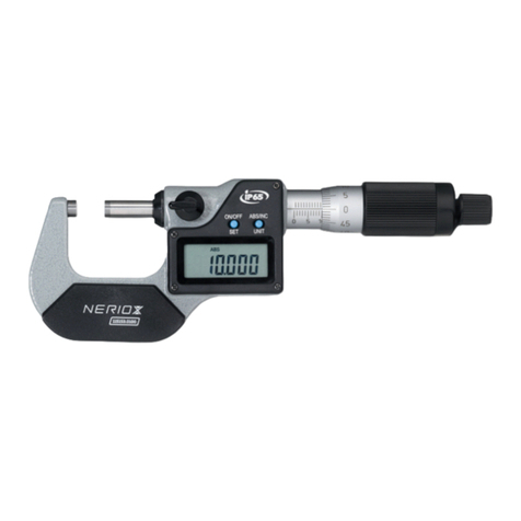
Neriox 137781 User manual

1
H‘henmess- und Anreissger¬t HD
Bedienungsanleitung 2
Height Gauge and Scribing Instrument HD
Operating instructions 4
Mesureur et traceur HD
Mode d’emploi 6
Misuratore di altezza e strumento
di tracciatura digitale HD
Istruzioni per l‘uso 8
Instrumento de medicin de altura
con trazador HD
Instrucciones de uso 10
Magassøgm«rő «s jel‘lő HD
Használati utasítás 12
Wysokościomierz traserski HD
Instrukcja obsługi 14
Altimetru şi aparat de trasat HD
Instrucţiuni de utilizare 16
Y⁄kseklik ‘l≈me ve
markalama cihaz HD
Çalıştırma talimatı 18
137781

2
DIGITALES H¥HENMESS/ANREISSGER¢T
HD
Bedienungsanleitung
137781
Bauteile
1. Basis
2. Batteriefachdeckel
3. Handrad
4. OFF/AUS-Taste
5. Anschlag Verriegelungsgri
6. Verriegelungsgri
7. Fixierschraube
8. Feinjustierung
9. Hauptskala
10. Säule
11 Endanschlag
12. Anzeige
13. mm/inch-Taste
14. ON/EIN und ZERO/Null-Taste
15. Voreinstellung +
16. Voreinstellung -
17. Grundträger zu Anreissnadel
18. Anreissnadelhalter
19. Anreissnadel
MAN_BRW _vers. July. 19_art. BRW 137781
1
2
3
4
9
10
11
5
6
7
8
12
13
14
15
16
17
18
19
Einleitung
Digitales Höhenmess- und Anreissgerät mit Feinverstellung. Robuster Sockel mit geschliener Standfläche. Grosse, gut lesbare LCD-Anzeige,
hartmetallbestückte Reissnadel.
Wichtige Hinweise:
• Vor derVerwendung des Gerätes die Oberfläche der Säule mit einem trockenen, sauberen und fusselfreien Lappen säubern (oder mit Reinigungsöl).
Das Messgerät vor wasserhaltigen Flüssigkeiten schützen.
• Legen Sie an kein Bauteil des Höhenmessgeräts eine Spannung an (z.B. beim Elektrogravieren), da dies den Schaltkreis beschädigen könnte.
• Seien Sie vorsichtig, die Anreissnadel (19) ist scharantig!
• Sorgen Sie dafür, dass keine Metallspäne oder sonstige Fremdkörper in die Zahnstange an der Rückseite der Säule gelangen.
• Achten Sie insbesondere darauf, dass die Fixierschraube (7) und derVerriegelungsgri (6) nicht fest angezogen sind, wenn Sie das Handrad (3) betätigen.
Andernfalls kann das Zahnrad beschädigt werden.

3
Br⁄tsch/R⁄egger Werkzeuge AG, Heinrich Stutz-Strasse 20, Postfach, CH-8902 Urdorf, Tel. +41 44 736 63 63, Fax +41 44 736 63 00, www.neriox.tools, [email protected]
Bedienung
• Die Oberfläche der Säule, der Basis (1) und derAnreissnadel (19) reinigen. Anreissnadel mit Halter (18) auf Grundträger (17) xieren.
• Arbeitsfläche reinigen und Höhenmessgerät darauf stellen. ON/Ein-Taste (14) betätigen. Verriegelung (6) und Fixierschraube (7) lösen und den
Schlitten mittels Handrad (3) bewegen, um die korrekte Funktion derAnzeige (12) zu prüfen.
• Um den Schlitten zu bewegen, drehen Sie das Handrad (3). Normalerweise sollte der Verriegelungsgri (6) in der forderen, d.h. losen Stellung sein;
drücken Sie ihn nach hinten, um den Schlitten zu verriegeln. Bei Benutzung der Feinjustierung (8) muss derVerriegelungshebel gelöst und die
Fixierschraube (7) angezogen sein.
• Voreinstellen des Anfangsmesspunkts. Normalerweise ist die Arbeitsfläche der Nullpunkt der Messung. Führen Sie dafür die folgenden Schritte
aus: Fahren Sie mit der Anreissnadel (19) leicht auf die Arbeitsfläche (Messkraft ca. 3-5 N); Anzeige sollte 0 anzeigen, andernfalls betätigen Sie die
ON/ZERO-Taste (14), um die Nullposition zu übernehmen. Es ist auch möglich mit ADD+ (15) und SUB- (16) einen Vorwahlwert (Preset) im
Minus- oder Plusbereich einzustellen.
Reparaturen
Sollte eine Reparatur Ihres Gerätes notwendig werden, so wenden Sie sich bitte an unser Servicecenter →Servicecenter@brw.ch
Fehler und deren Behebung
Fehler mögliche Ursachen Lösung
Blinkende Zahlen geringe Spannung Batterie austauschen
Keine Anzeige geringe Spannung Batterie austauschen
schlechte Kontakte Batteriesitz korrigieren, Kontakte reinigen
Unveränderliche Werte Störung im Schaltkreis Batterie herausnehmenund nach einer Minute wieder einsetzen
Austausch der Batterie
Auälligkeiten derAnzeige (blinkende Zahlen oder gar keine Anzeige) deuten
auf eine schwache Batterie hin, die Sie austauschen müssen. Entfernen Sie dazu
den Batteriefachdeckel in Pfeilrichtung und legen Sie eine neue Batterie vom
Typ SR44W/1,55 V ein.
Hinweis
• Der Pluspol der Batterie muss nach außen zeigen.
• Nach dem Austausch der Batterie müssen Sie den Messnullpunkt neu einstellen.
MAN_BRW _vers. July. 19_art. BRW 137781
Technische Daten
Messbereich 0-300 mm bzw. 0-600 mm (je nach Modell)
Auflösung 0,01 mm
Wiederholgenauigkeit 0,01 mm
Max. Reaktionsgeschw. 1 m/s
Stromvers. Knopfzelle SR44W, Spannung 1,55 V
Betriebsbedingungen Temperatur 5-35°C, Relative Feuchte <60 %
Tastenfunktionen
OFF Anzeige ausschalten
ON/ZERO Anzeige aktivieren und Nullpunkt setzen
mm/inch mm oder inch einstellen
ADD+ Voreinstellwert plus
SUB- Voreinstellwert minus

4
DIGITAL HEIGHT GAUGE / SCRIBING INST
RUMENT HD
Operating instructions
137781
Components
1. Base
2. Battery compartment cover
3. Handwheel
4. OFF button
5. Locking handle stop
6. Locking handle
7. Fixing screw
8. Fine adjustment
9. Main scale
10. Column
11 End stop
12. Display
13. mm / inch button
14. ON and ZERO button
15. Preset +
16. Preset -
17. Base for scribing needle
18. Scribing needle holder
19. Scribing needle
1
2
3
4
9
10
11
5
6
7
8
12
13
14
15
16
17
18
19
Introduction
Digital height gauge and scribing instrument with ne adjustment. Robust stand with polished base. Large, easy-to-read LCD display,
carbide-tipped scriber.
Important notes:
• Before using the device, clean the surface of the column with a, dry, clean, lint-free cloth (or cleaning oil).
Protect the measuring device from aqueous fluids.
• Never apply voltage to any part of the height gauge (e.g. during electrical engraving), as this could damage the circuit.
• Be careful, the marking needle (19) has sharp edges!
• Prevent metal shavings or foreign objects from getting into the gear rack at the rear of the column.
• Especially ensure that the fastening screw (7) and locking handle (6) are not rmly tightened when you activate the handwheel (3).
Otherwise the gear wheel may become damaged.
MAN_BRW _vers. July. 19_art. BRW 137781

5
Br⁄tsch/R⁄egger Werkzeuge AG, Heinrich Stutz-Strasse 20, Postfach, CH-8902 Urdorf, Tel. +41 44 736 63 63, Fax +41 44 736 63 00, www.neriox.tools, [email protected]Br⁄tsch/R⁄egger Werkzeuge AG, Heinrich Stutz-Strasse 20, Postfach, CH-8902 Urdorf, Tel. +41 44 736 63 63, Fax +41 44 736 63 00, www.neriox.tools, [email protected]
Operation
• Clean the surface of the column, base (1) and scribing needle (19). Fix the scribing needle to the base (17) with the bracket (18).
• Clean the work surface and place the height gauge on it. Activate the ON button (14). Loosen the lock (6) and fastening screw (7) and move
the slider via the handwheel (3) to check for correct function of the display (12).
• To move the slider, turn the handwheel (3). Normally, the locking handle (6) should be in the front, i.e. loose, position;
push it back to lock the slider. When using the ne adjustment mechanism (8), the locking lever must be loosened and the
fastening screw (7) must be tightened.
• Presetting the starting point of the measurement. The work surface is usually the zero point of the measurement. For this, carry out the
following steps:
Move the scribing needle (19) lightly over the work surface (measurement force approx. 3-5-N); the display should show 0, if not activate the
ON/ZERO button (14) to apply the zero position. It is also possible to set a preset value in the plus or minus range with ADD+ (15) and SUB- (16).
Repairs
Should the instrument need to be repaired, please contact our Service Centre →center@brw.ch
Errors and howto x them
Error Possible causes Solution
Flashing digits Low voltage Replace battery
No display Low voltage Replace battery
Poor contacts Correct battery t, clean contacts
Constant values Fault in circuit Remove battery, wait for one minute and reinsert
Replacing the battery
An abnormal display (flashing digits or no display) indicates
a weak battery that must be replaced. To do this,
remove the battery compartment cover in the direction shown by the
arrow and replace the battery with a new SR44W/1.55V battery.
Note
• The positive pole of the battery must face outward.
• After replacing the battery, reset the zero point of measurement.
MAN_BRW _vers. July. 19_art. BRW 137781
Technical data
Measuring range 0-300 mm / 0-600 mm (depending on model)
Resolution 0.01 mm
Repeat accuracy 0.01 mm
Max. reaction speed 1 m/s
Power supply SR44W button cell, voltage 1.55 V
Operating conditions Temperature 5-35 ° C, relative humidity <60%
Button functions
OFF Switch o display
ON/ZERO Activate display and set zero point
mm/inch Set mm or inch
ADD+ Preset value plus
SUB- Preset value minus

6
MESUREUR ET TRACEUR DIGITAL HD
Mode d’emploi
137781
Composants
1. Base
2. Couvercle du compartiment de la pile
3. Volant
4. Touche OFF/ARRÊT
5. Butée de la poignée de verrouillage
6. Poignée de verrouillage
7. Vis de xation
8. Réglage n
9. Échelle principale
10. Colonne
11 Butée d’extrémité
12. Écran
13. Touche mm/pouces
14. Touche ON/MARCHE et ZERO/zéro
15. Préréglage +
16. Préréglage -
17. Support de base de la pointe à tracer
18. Porte-pointe à tracer
19. Pointe à tracer
MAN_BRW _vers. July. 19_art. BRW 137781
1
2
3
4
9
10
11
5
6
7
8
12
13
14
15
16
17
18
19
Introduction
Mesureur et traceur digital avec réglage n. Socle robuste avec surface d’appui polie. Grand écran à cristaux liquides à bonne lisibilité,
pointe à tracer au carbure.
Remarques importantes :
• Avant l’utilisation de l’appareil, toujours nettoyer la surface de la colonne à l’aide d’un chion sec, propre et non pelucheux (ou à l’aide d’huile de nettoyage).
Protéger l’instrument de mesure contre les liquides aqueux.
• N’appliquez aucune tension sur un composant du mesureur (par ex. pendant la gravure électrique), cela risquerait de détruire le circuit de commutation.
• Soyez prudent, la pointe à tracer (19) est tranchante !
• Veillez à exclure toute chute de copeaux métalliques ou d’autres corps étrangers dans la crémaillère au dos de la colonne.
• Veillez notamment à ce que la vis de xation (7) et la poignée de verrouillage (6) ne soient pas serrées à fond lorsque vous actionnez le volant (3).
Le contraire, la roue dentée peut être endommagée.

7
Br⁄tsch/R⁄egger Werkzeuge AG, Heinrich Stutz-Strasse 20, Postfach, CH-8902 Urdorf, Tel. +41 44 736 63 63, Fax +41 44 736 63 00, www.neriox.tools, [email protected]
Utilisation
• Nettoyer la surface de la colonne, de a base (1) et de la pointe à tracer (19). Fixer la pointe à tracer avec support (18) sur le support de base (17).
• Nettoyer la surface de travail puis y déposer le mesureur. Appuyer sur la touche ON/Marche (14). Desserrer le verrouillage (6) et la vis de xation (7)
puis déplacer le chariot à l’aide du volant (3) an de s’assurer du fonctionnement correct de l’écran (12).
• Pour déplacer le chariot, tournez le volant (3). Normalement, la poignée de verrouillage (6) se trouve en position avant, c.-à-d. sans xation ;
poussez-la vers l’avant pourverrouiller le chariot. En cas d’utilisation du réglage n (8), le levier de verrouillage doit être desserré et la vis
de xation (7) doit être serrée.
• Prérégler le point de mesure initial. En temps normal, la surface de travail représente le point zéro de la mesure. À cet eet, exécutez les étapes
suivantes : déplacez légèrement la pointe à tracer (19) sur la surface de travail (pression de mesure env. 3 à 5 N) ; la valeur 0 devrait être achée
sur l’écran ; le cas contraire, appuyez sur la touche ON/ZERO (14) pour valider la position zéro. Il est également possible de congurer une valeur
de préréglage (présélection) dans la plage négative ou positive à l’aide des touches ADD+ (15) et SUB- (16).
Réparations
S’il devait s’avérer nécessaire de réparervotre appareil, veuillez contacter notre centre S.A.V. Servicecenter@brw.ch
Erreurs et leur dépannage
Erreur Causes possibles Solution
Chires clignotantes Faible tension Remplacer la pile
Aucun achage Faible tension Remplacer la pile
Mauvais contacts Corriger la position de la pile, nettoyer les contacts
Valeurs invariables Défaut sur le circuit de commutation Retirer la pile puis attendre une minute avant de la remettre en place
Remplacement de la pile
Les problèmes d’achage (chires clignotants ou aucun achage) indiquent que la pile est presque vide et que vous devez la remplacer. À cet eet,
retirez le couvercle du compartiment de la pile dans le sens de la flèche puis insérez une pile neuve du type SR44W/1,55 V.
Remarque
• La borne plus de la pile doit pointer vers l’extérieur.
• Après avoir remplacé la pile, vous devez reprogrammer le point zéro de la mesure.
MAN_BRW _vers. July. 19_art. BRW 137781
Caractéristiques techniques
Plage de mesure 0-300 mm ou 0-600 mm (selon le modèle)
Résolution 0,01 mm
Reproductibilité 0,01 mm
Vitesse de réaction max. 1 m/s
Alimentation électr. Pile ronde SR44W, tension 1,55 V
Conditions d’exploitation Température 5-35 °C, humidité relative <60 %
Fonctions de touches
OFF Mise hors circuit de l’écran
ON/ZERO Mise en circuit de l’écran et réinitialisation du point zéro
mm/inch Achage en mm ou pouces
ADD+ Valeur de préréglage Plus
SUB- Valeur de préréglage Moins

8
MISURATORE DI ALTEZZA E STRUMENTO
DI TRACCIATURA DIGITALE HD
Istruzioni per l‘uso
137781
Componenti
1. Base
2. Coperchio vano batteria
3. Volantino
4. Tasto OFF/AUS
5. Battuta maniglia di bloccaggio
6. Maniglia di bloccaggio
7. Vite di ssaggio
8. Regolazione di precisione
9. Scala principale
10. Colonna
11 Battuta nale
12. Display
13. Tasto mm/pollici
14. Tasto ON e ZERO
15. Preregolazione +
16. Preregolazione +
17. Telaio base punta per tracciare
18. Supporto punta per tracciare
19. Punta per tracciare
MAN_BRW _vers. July. 19_art. BRW 137781
1
2
3
4
9
10
11
5
6
7
8
12
13
14
15
16
17
18
19
Introduzione
Misuratore di altezza e strumento di tracciatura con regolazione di precisione Base robusta con supercie di appoggio retticata. Grande display LCD di facile lettura,
punta per tracciare in metallo duro.
Avvertenze importanti:
• Prima di utilizzare l‘apparecchio pulire la supercie della colonna con un panno pulito, asciutto e non lamentoso (o con olio di pulizia).
Proteggere lo strumento di misura da liquidi contenenti acqua.
• Non applicare tensione su nessun componente del misuratore di altezza (ad esempio in caso di incisione elettrica), perché questo potrebbe danneggiare
il circuito di commutazione.
• Agire con cautela, la punta per tracciare (19) è alata!
• Assicurarsi che né trucioli metallici né altri corpi estranei giungano nella cremagliera sul lato posteriore della colonna.
• Assicurarsi in particolare che la vite di ssaggio (7) e la maniglia di bloccaggio (6)
non siano saldamente serrati quando si aziona il volantino (3).
In caso contrario la ruota dentata potrebbe essere danneggiata.

9
Br⁄tsch/R⁄egger Werkzeuge AG, Heinrich Stutz-Strasse 20, Postfach, CH-8902 Urdorf, Tel. +41 44 736 63 63, Fax +41 44 736 63 00, www.neriox.tools, [email protected]Br⁄tsch/R⁄egger Werkzeuge AG, Heinrich Stutz-Strasse 20, Postfach, CH-8902 Urdorf, Tel. +41 44 736 63 63, Fax +41 44 736 63 00, www.neriox.tools, [email protected]
MAN_BRW _vers. July. 19_art. BRW 137781
Comando
• Pulire la supercie della colonna, della base (1) e della punta per tracciare (19). Fissare la punta per tracciare con il supporto (18) sul telaio base (17).
• Pulire la supercie di lavoro e collocarvi sopra il misuratore di altezza. Premere il tasto ON (14). Allentare il bloccaggio (6) e la vite di ssaggio (7) e
muovere la slitta per mezzo del volantino (3) per vericare il corretto funzionamento del display (12).
• Per spostare la slitta ruotare il volantino (3). Normalmente la maniglia di bloccaggio (6) dovrebbe trovarsi nella posizione anteriore ovvero allentata;
premerla verso il lato posteriore per bloccare la slitta. In caso di utilizzo della regolazione di precisione (8) la leva di bloccaggio deve essere allentata
e la vite di ssaggio (7) serrata.
• Preimpostazione del punto di inizio della misurazione. Normalmente la supercie di lavoro rappresenta il punto zero della misurazione. A questo
scopo eseguire le seguenti operazioni: Muovere la punta per tracciare delicatamente (19) sulla supercie di lavoro (forza di misurazione circa 3-5 N);
il display dovrebbe visualizzare 0, in caso contrario premere il tasto ON/ZERO (14), per applicare la posizione zero. È anche possibile impostare un valore
di preselezione (Preset) con ADD+ (15) e SUB- (16) nell‘area di Meno o Più.
Riparazioni
Se dovesse essere necessario eettuare una riparazione del vostro apparecchio, rivolgersi al nostro centro servizi →Servicecenter@brw.ch
Errori e rimedio
Errori possibili cause risoluzione
Cifre lampeggianti Bassa tensione Sostituire la batteria
Nessuna visualizzazione Bassa tensione Sostituire la batteria
Contatti difettosi Correggere la sede delle batterie; Pulire i contatti
Valori non variano Guasto nel circuito Togliere la batteria e reinserirla dopo un minuto
Sostituzione della batteria
Eventuali anomalie del display (cifre lampeggianti o nessuna visualizzazione)
indicano che la batteria è debole ed è necessario sostituirla. Rimuovere pertanto
il coperchio del vano batterie in direzione della freccia e inserire una nuova batteria del
tipo SR44W/1,55 V.
Avvertenza
• Il polo positivo della batteria deve indicare verso l‘esterno.
• Dopo aver sostituito la batteria è necessario impostare di nuovo il punto zero di misurazione.
Dati tecnici
Campo di misura 0-300 mm o 0-600 mm (a seconda del modello)
Risoluzione 0,01 mm
Accuratezza di ripetizione 0,01 mm
Velocità max. di reazione 1 m/s
Alim. elettr. Batteria a bottone SR44W, tensione 1,55 V
Condizioni di funzionamento Temperatura 5-35°C, Umidità relativa <60 %
Funzioni dei tasti
OFF Spegnere il display
ON/ZERO Attivare il display e denire il punto zero
mm/inch impostare mm o inch (pollici)
ADD+ Valore preimpostato Più
SUB- Valore preimpostato Meno

10
INSTRUMENTO DE MEDICI±N DE ALTURA
CON TRAZADOR HD
Instrucciones de uso
137781
Componentes
1. Base
2. Tapa del compartimento de la pila
3. Rueda manual
4. Botón de encendido y apagado
5. Tope del mando de bloqueo
6. Mando de bloqueo
7. Tornillo de jación
8. Ajuste de precisión
9. Escala principal
10. Columna
11 Tope nal
12. Pantalla
13. Botón de mm/pulgadas
14. Botón ON/Encender y ZERO/Cero
15. Ajuste previo +
16. Ajuste previo -
17. Apoyo base para la aguja de trazar
18. Soporte de la aguja de trazar
19. Aguja de trazar
MAN_BRW _vers. July. 19_art. BRW 137781
1
2
3
4
9
10
11
5
6
7
8
12
13
14
15
16
17
18
19
Introducción
Instrumento digital de medición de altura con trazador y ajuste de precisión. Base robusta con supercie de apoyo pulida. Pantalla LCD de gran tamaño y fácil de leer,
trazador de metal duro.
Indicaciones importantes:
• Antes de utilizar el equipo, limpie la supercie de la columna con un paño limpio, seco y sin pelusas (o con aceite de limpieza).
Proteja el instrumento de medición de los líquidos que contengan agua.
• No exponga a tensión eléctrica ningún componente del instrumento de medición de altura (p. ej. electrograbado), ya que el circuito podría resultar dañado.
• Tenga mucho cuidado con la aguja de trazar (19). ¡Está muy alada!
• Tenga cuidado de que no entren virutas metálicas u otros cuerpos extraños en la cremallera de la parte posterior de la columna.
• Preste especial atención a que el tornillo de jación (7) y el mando de bloqueo (6) no estén apretados cuando accione la rueda manual (3).
De lo contrario, el engranaje podría resultar dañado.

11
Br⁄tsch/R⁄egger Werkzeuge AG, Heinrich Stutz-Strasse 20, Postfach, CH-8902 Urdorf, Tel. +41 44 736 63 63, Fax +41 44 736 63 00, www.neriox.tools, [email protected]
Manejo
• Limpie la supercie de la columna, la base (1) y la aguja de trazar (19). Fije la aguja de trazar al apoyo base (17) con el soporte (18).
• Limpie la supercie de mecanizar y coloque el instrumento de medición de la altura encima. Pulse el botón ON/Encender (14). Suelte el mando de
bloqueo (6) y el tornillo de jación (7) y mueva el carro con la rueda manual (3) para comprobar que la pantalla (12) funcione correctamente.
• Para mover el carro, gire la rueda manual (3). Por regla general, el mando de bloqueo (6) debe estar en la posición delantera (soltar);
presiónelo hacia atrás para desbloquear el carro. Para utilizar el ajuste de precisión (8), la palanca de bloqueo debe estar soltada y
el tornillo de jación (7) debe estar apretado.
• Preajuste del punto de medición inicial. Como norma general, el punto cero de la medición es la supercie de mecanizar. Realice las operaciones
que se indican a continuación: desplace la aguja de trazar (19) ligeramente contra la supercie de mecanizar (fuerza de medición aprox. 3-5 N);
en la pantalla debe mostrarse 0; de lo contrario, pulse el botón ON/ZERO (14) para establecer la posición cero. También se puede seleccionar un
preajuste (Preset) en el rango positivo o negativo con ADD+ (15) y SUB- (16).
Reparaciones
Si fuera necesario realizar alguna reparación en el equipo, póngase en contacto con nuestro servicio de atención al cliente: → Servicecenter@brw.ch
Problemas y solución
Problema Causas posibles Solución
Los números parpadean Tensión insuciente Cambiar la pila
Pantalla en blanco Tensión insuciente Cambiar la pila
Mal contacto Corregir la posición de la pila, limpiar los contactos
Los valores no cambian Fallo en el circuito Quitar la pila, esperar un minuto y colocarla de nuevo
Cambio de la pila
Si la pantalla deja de funcionar con normalidad (los números parpadean o
no se muestra nada), signica que la pila está gastada y se tiene que cambiar. Extraiga la
tapa del compartimento de la pila en la dirección de la flecha e inserte
una pila nueva de tipo SR44W/1,55 V.
Nota
• El polo positivo de la pila debe mirar hacia fuera.
• Después de cambiar la pila se tiene que volver a ajustar el punto cero de la medición.
MAN_BRW _vers. July. 19_art. BRW 137781
Datos técnicos
Rango de medición 0-300 mm o 0-600 mm (según el modelo)
Resolución 0,01 mm
Precisión de repetición 0,01 mm
Velocidad máx. reacción 1 m/s
Alimentación Pila de botón SR44W, tensión 1,55 V
Condiciones de servicio Temperatura 5-35 °C, humedad relativa <60 %
Funciones de los botones
OFF Apagar la pantalla
ON/ZERO Activar la pantalla y denir el punto cero
mm/inch Seleccionar mm o pulgadas
ADD+ Aumentar el valor de preajuste
SUB- Reducir el valor de preajuste

12
DIGITüLIS MAGASSüGMßRŐ/JEL¥LŐ HD
Használati utasítás
137781
Alkatrészek
1. Alap
2. Elemrekesz-fedél
3. Kézikerék
4. OFF/KI gomb
5. Reteszelő kar ütköző
6. Reteszelő fogantyú
7. Rögzítőcsavar
8. Finombeállító
9. Főskála
10. Oszlop
11 Ütköző
12. Kijelző
13. mm/col gomb
14. ON/BE és ZERO/nulla gomb
15. Előbeállítás +
16. Előbeállítás -
17. Jelölőtű főtartó
18. Jelölőtű tartó
19. Jelölőtű
MAN_BRW _vers. July. 19_art. BRW 137781
1
2
3
4
9
10
11
5
6
7
8
12
13
14
15
16
17
18
19
Bevezető
Digitális magasságmérő és jelölő nombeállítóval. Robusztus talp köszörült állófelülettel. Nagy, jól leolvasható LCD kijelző,
keményfém hegyű jelölőtű.
Fontos tudnivalók:
• Az eszköz használata előtt tisztítsa meg az oszlop felületét száraz, tiszta és szöszmentes ronggyal (vagy tisztító olajjal).
Óvja a mérőeszközt víztartalmú folyadékoktól.
• Ne helyezze az eszköz alkatrészeit feszültség alá (pl. elektromos gravírozásnál), mivel ez kárt tehet az áramkört.
• Legyen elővigyázatos, a jelölőtű (19) hegyes!
• Gondoskodjon arról, hogy ne kerüljenekfémforgácsokvagy más idegen testek az oszlop hátoldalán található fogaslécbe.
• Különösen ügyeljen arra, hogy ne legyen szorosan meghúzva a rögzítőcsavar (7) és a reteszelő kar (6), ha a kézikereket (3) működteti.
Ellenkező esetben megsérülhet a fogaskerék.

13
Br⁄tsch/R⁄egger Werkzeuge AG, Heinrich Stutz-Strasse 20, Postfach, CH-8902 Urdorf, Tel. +41 44 736 63 63, Fax +41 44 736 63 00, www.neriox.tools, [email protected]
Használat
• Tisztítsa meg az oszlop, az alap (1) és a jelölőtű (19) felületét. Rögzítse a jelölőtűt a tartóval (18) a főtartón (17).
• Tisztítsa meg a munkafelületet, majd helyezze rá a magasságmérőt. Nyomja meg az ON/BE gombot (14). Oldja ki a reteszelést (6) és lazítsa
meg a rögzítőcsavart (7), majd mozgassa a szánt a kézikerékkel (3) a kijelző (12) megfelelő működésének ellenőrzése érdekében.
• A szán mozgatásához forgassa el a kézikereket (3). A reteszelő karnak (6) rendszerint az elülső, azaz a kioldott helyzetben kell lennie;
nyomja hátra a szán reteszeléséhez. A nombeállító (8) használatakor a reteszelő karnak kioldva és a
rögzítőcsavarnak (7) meghúzva kell lennie.
• Állítsa be a kiindulási mérőpontot. Rendszerint a mérés nullapontja a munkafelület. Ehhez végezze el az alábbi
lépéseket: Vigye a jelölőtűt (19) a munkafelületre (mérőerő kb. 3-5 N); a kijelzőnek 0 értéket kell mutatnia, ellenkező esetben nyomja meg az
ON/ZERO gombot (14) a nullhelyzet átvételéhez. Az ADD+ (15) és SUB- (16) gombokkal lehetőség van egy alapértelmezett érték beállítására
negatív vagy pozitív tartományban.
Javítások
Amennyiben a készülék javításra szorulna, úgy kérjük, forduljon a szervizközpontunkhoz →Servicecenter@brw.ch
Hibaelhárítás
Hiba Lehetséges ok Megoldás
Villogó számok Alacsony feszültség Az elem cseréje
Nincs kijelzés Alacsony feszültség Az elem cseréje
Nem megfelelő érintkezés Az elem helyzetétnek korrigálása, érintkezők tisztítása
Változatlan értékek Áramköri hiba Az elem eltávolítása, majd visszahelyezése néhány perc elteltével
Az elem cseréje
A kijelzőn jelentkező anomáliák (villogó számok vagy nincs kijelzés)
lemerült elemre utalnak, amelyet ki kell cserélni. Ehhez távolítsa el
az elemrekesz fedelét a nyíl irányában, majd helyezze be egy új
SR44W/1,55 V típusú elemet.
Értesítés
• Az elem pozitív pólusának kifelé kell mutatnia.
• Az elem cseréje után újra be kell állítani a mérési nullpontot.
MAN_BRW _vers. July. 19_art. BRW 137781
Műszaki adatok
Méréstartomány 0-300 mm, ill. 0-600 mm (modelltől függően)
Felbontás 0,01 mm
Ismétlési pontosság 0,01 mm
Max. reakcióseb. 1 m/s
Áramell. SR44W típusú gombelem, feszültség: 1,55 V
Működési feltételek hőmérséklet: 5-35 °C, relatív páratartalom <60%
Gombfunkciók
OFF kijelző kikapcsolása
ON/ZERO kijelző bekapcsolása és nullapont beállítása
mm/col mm vagy col beállítása
ADD+ előre beállított érték növelése
SUB- előre beállított érték csökkentése

14
WYSOKOŚCIOMIERZ TRASERSKI HD
Instrukcja obsługi
137781
Podzespoły
1. Podstawa
2. Pokrywa pojemnika baterii
3. Pokrętło
4. Przycisk OFF/WYŁ.
5. Ogranicznik uchwytu blokującego
6. Uchwyt blokujący
7. Śruba blokująca
8. Precyzyjna regulacja
9. Główna skala
10. Kolumna
11. Ogranicznik krańcowy
12. Wyświetlacz
13. Przycisk mm/inch
14. Przycisk ON/WŁ. i ZERO
15. Ustawienie wstępne +
16. Ustawienie wstępne -
17. Podstawa uchwytu rysika traserskiego
18. Uchwyt rysika traserskiego
19. Rysik traserski
MAN_BRW _vers. July. 19_art. BRW 137781
1
2
3
4
9
10
11
5
6
7
8
12
13
14
15
16
17
18
19
Wprowadzenie
Wysokościomierz traserski z precyzyjną regulacją. Trwała podstawa ze szlifowaną powierzchnią podstawy. Duży, dobrze czytelny wyświetlacz LCD,
rysik traserski zakończony węglikami spiekanymi.
Ważne wskazówki:
• Przed użyciem przyrządu powierzchnię kolumny należy wyczyścić za pomocą suchej, czystej i niekłaczącej szmatki (lub za pomocą oleju do czyszczenia).
Miernik chronić przed płynami zawierającymi wodę.
• Żadnego elementu wysokościomierza nie podłączać do prądu elektrycznego (np. podczas elektrograwerowania), ponieważ może to spowodować
uszkodzenie układu elektronicznego.
• Należy zachować ostrożność, rysik traserski (19) ma ostre krawędzie!
• Należy zadbać, aby do przekładni zębatej z tyłu kolumny nie przedostały się żadne wióry metalowe lub inne ciała obce.
• W szczególności należy zwrócić uwagę, aby podczas operowania pokrętłem (3) nie były
dociągnięte śruba blokująca (7) i uchwyt blokujący (6).
W przeciwnym wypadku może dojść do uszkodzenia koła zębatego.

15
Br⁄tsch/R⁄egger Werkzeuge AG, Heinrich Stutz-Strasse 20, Postfach, CH-8902 Urdorf, Tel. +41 44 736 63 63, Fax +41 44 736 63 00, www.neriox.tools, [email protected]
Obsługa
• Wyczyścić powierzchnie kolumny, podstawy (1) i rysika traserskiego (19). Rysik traserski z uchwytem (18) zamontować na jego podstawie (17).
• Wyczyścić powierzchnię roboczą i ustawić na niej wysokościomierz. Nacisnąć przycisk ON/WŁ. (14). Zwolnić blokadę (6) i śrubę blokującą (7)
i poruszyć sanki za pomocą pokrętła (3), aby sprawdzić prawidłowe działanie wyświetlacza (12).
• Aby poruszać sankami, należy kręcić pokrętłem (3). Normalnie uchwyt blokujący (6) powinien znajdować się w przedniej pozycji, tzn. odblokowania;
aby zablokować sanki, należy przechylić go do tyłu. Podczas korzystania z precyzyjnej regulacji (8) dźwignia blokady musi być zwolniona, a śruba
blokująca (7) dokręcona.
• Ustawienie wstępne początkowego punktu pomiaru. Zazwyczaj punktem zerowym pomiaru jest powierzchnia robocza. W tym celu należy wykonać
następujące czynności: rysik traserski (19) lekko docisnąć do powierzchni roboczej (siła pomiaru ok. 3–5 N); wyświetlacz powinien wskazywać 0,
w przeciwnym razie należy nacisnąć przycisk ON/ZERO (14), aby zastosować pozycję zerową. Możliwe jest również ustawienie, zmniejszenie lub
zwiększenie) wartości wstępnej (preset) za pomocą przyciskówADD+ (15) i SUB- (16).
Naprawy
W przypadku konieczności naprawy urządzenia prosimy o kontakt z naszym centrum serwisowym →Servicecenter@brw.ch
Usterki i ich usuwanie
Usterka Możliwa przyczyna Rozwiązanie
Migające cyfry Niskie napięcie Wymienić baterię
Brakwskazania Niskie napięcie Wymienić baterię
Brak styku Skorygować osadzenie baterii, wyczyścić styki
Brak zmiany wskazania Błąd układu elektronicznego Wyjąć baterię i po minucie ponownie zamontować
Wymiana baterii
Nietypowe zachowanie wyświetlacza (miganie cyfr lub ich niewyświetlanie) wskazują na słabą baterię, która musi zostać wymieniona. W tym celu
należy zdemontować pokrywę pojemnika baterii, zgodnie z kierunkiem strzałki, i zamontować nową baterię typu SR44W/1,55 V.
Wskazówka
• Biegun dodatni musi wskazywać na zewnątrz.
• Po wymianie baterii konieczne jest ponowne ustawienie punktu zerowego.
MAN_BRW _vers. July. 19_art. BRW 137781
Dane techniczne
Zakres pomiaru 0–300 mm wzgl. 0–600 mm (zależnie od modelu)
Rozdzielczość 0,01 mm
Powtarzalność 0,01 mm
Maks. prędkość reakcji 1 m/s
Zasilanie el. bateria guzikowa SR44W, napięcie 1,55 V
Warunki pracy temperatura 5–35°C, wilgotność wzgl. <60%
Funkcje przycisków
OFF wyłączenia wyświetlacza
ON/ZERO aktywacja wyświetlacza i ustawianie zera
mm/inch ustawianie jednostki mm lub inch
ADD+ wartość wstępna plus
SUB- wartość wstępna minus

16
ALTIMETRU ŞI APARAT DE TRASAT DIGITAL
HD
Instrucţiuni de utilizare
137781
Componente
1. Bază
2. Capac compartiment baterii
3. Rotiţă de manevră
4. Buton OFF/OPRIT
5. Opritor mâner de blocare
6. Mâner de blocare
7. Şurub de xare
8. Reglaj n
9. Scală principală
10. Coloană
11 Opritor de capăt
12. Aşaj
13. Buton mm/inch
14. Buton ON/PORNIT şi buton ZERO/zero
15. Presetare +
16. Presetare -
17. Suport de bază pentru acul de trasat
18. Suport ac de trasat
19. Ac de trasat
MAN_BRW _vers. July. 19_art. BRW 137781
1
2
3
4
9
10
11
5
6
7
8
12
13
14
15
16
17
18
19
Introducere
Altimetru şi aparat de trasat digital cu reglaj n. Soclu robust cu suprafaţă-suport şlefuită. Ecran LCD generos, bine lizibil,
ac de trasat din carbură metalică.
Observaţii importante:
• Înainte de utilizarea aparatului curăţaţi suprafaţa coloanei cu o lavetă uscată, curată şi care nu lasă scame (sau cu ulei de curăţare).
Protejaţi aparatul de măsură de lichidele cu conţinut de apă.
• Nu aplicaţi curent electric la nicio componentă a altimetrului (de exemplu, la gravarea electrică) deoarece s-ar putea deteriora circuitul electric.
• Utilizaţi acul de trasat (19) în mod precaut deoarece este ascuţit!
• Acordaţi atenţie nepătrunderii aşchiilor metalice sau altor impurităţi în bara dinţată de pe partea posterioară a coloanei.
• Acordaţi atenţie în mod special şurubului de xare (7) şi mânerului de blocare (6) să nu e strânse până la capăt dacă acţionaţi rotiţa de manevră (3).
În caz contrar se poate deteriora rotiţa dinţată.

17
Br⁄tsch/R⁄egger Werkzeuge AG, Heinrich Stutz-Strasse 20, Postfach, CH-8902 Urdorf, Tel. +41 44 736 63 63, Fax +41 44 736 63 00, www.neriox.tools, [email protected]
Utilizarea
• Curăţaţi suprafaţa coloanei, bazei (1) şi acului de trasat (19). Fixaţi acul de trasat cu suportul (18) pe suportul de bază (17).
• Curăţaţi suprafaţa de lucru şi aşezaţi pe ea altimetrul. Apăsaţi butonul ON/Pornit (14). Desfaceţi elementul de blocare (6) şi şurubul de xare (7) şi
deplasaţi cursorul cu ajutorul rotiţei de manevră (3) pentru a verica funcţionarea corectă a aşajului (12).
• Pentru a deplasa cursorul, învârtiţi rotiţa de manevră (3). În mod normal, mânerul de blocare (6) trebuie să se afle în poziţia din faţă, adică în poziţia deschisă;
apăsaţi-l spre spate pentru a bloca cursorul. În cazul utilizării reglajului n (8), trebuie desfăcută maneta de blocare şi
trebuie strâns şurubul de xare (7).
• Presetarea punctului de începere a măsurătorii. În mod normal, punctul zero al măsurătorii este suprafaţa de lucru. Pentru aceasta parcurgeţi următorii paşi
oprit: deplasaţi-vă cu acul de trasat (19) uşor pe suprafaţa de lucru (forţă de măsurare cca. 3-5 N); aşajul trebuie să indice 0. În caz contrar apăsaţi pe
butonul ON/ZERO (14) pentru a prelua poziţia zero. Cu ADD+ (15) şi SUB- (16) este posibil de asemenea să setaţi o valoare presetatp (Preset) în
domeniul negativ sau pozitiv.
Reparaţiile
Dacă este necesară repararea aparatului, vă rugăm să vă adresaţi Centrului nostru de service → Servicecenter@brw.ch
Erorile şi remedierea lor
Eroare cauze posibile soluţie
Cifre aprinse intermitent tensiune scăzută înlocuirea bateriei
Niciun aşaj tensiune scăzută înlocuirea bateriei
contacte slabe corectarea poziţiei bateriei, curăţarea contactelor
Valori nemodicabile defecţiune în circuitul elecric scoateţi bateria şi introduceţi-o la loc după un minut
Înlocuirea bateriei
Anomaliile aşajului (cifre aprinse intermitent sau niciun aşaj) indică
un nivel scăzut de încărcare a bateriei, care trebuie înlocuită. Pentru aceasta îndepărtaţi
capacul bateriei în direcţia indicată de săgeată şi introduceţi o nouă baterie de
tipul SR44W/1,55 V.
Indicaţie
• Polul pozitiv al bateriei trebuie să e orientat spre exterior.
• După înlocuirea bateriei trebuie să setaţi din nou punctul zero al măsurătorii.
MAN_BRW _vers. July. 19_art. BRW 137781
Date tehnice
Domeniu de măsurare 0-300 mm, respectiv 0-600 mm (în funcţie de model)
Rezoluţie 0,01 mm
Precizie de repetare 0,01 mm
Viteză max. de reacţie 1 m/s
alim. baterie de tip „nasture“ SR44W, tensiune 1,55 V
Condiţii de utilizare temperatură 5-35°C, umiditate relativă <60 %
Funcţiile butoanelor
OFF dezactivarea aşajului
ON/ZERO activarea aşajului şi setarea punctului zero
mm/inch setare mm sau inch
ADD+ valoare presetată pozitivă
SUB- valoare presetată negativă

18
DIJITALY∫KSEKLIK ¥LME VE MARKALA
MA CIHAZI HD
Çalıştırma talimatı
137781
Bileşenler
1. Baz
2. Pil kapağı
3. El çarkı
4. OFF / KAPALI tuşu
5. Kilitleme kolu durdurma
6. Kilitleme kolu
7. Sabitleme vidası
8. Hassas ayar
9. Ana ölçek
10. Kolon
11 Durak
12. Ekran
13. mm / inç düğmesi
14. ON / AÇMA ve ZERO / SIFIR düğmesi
15. Önayar +
16. Önayar -
17. Çizici iğnesi temel taşıyıcısı
18. Çizici iğnesi tutucusu
19. Çizici iğnesi
MAN_BRW _vers. July. 19_art. BRW 137781
1
2
3
4
9
10
11
5
6
7
8
12
13
14
15
16
17
18
19
Giris
Hassas ayarlı dijital yükseklik ölçme ve markalama cihazı. Cilalı alt yüzeyli sağlam taban. Geniş, okunması kolay LCD ekran,
karbür uçlu çizici.
Önemli notlar:
• Cihazı kullanmadan önce, kolon yüzeyini kuru, temiz ve tüy bırakmayan bir bezle (veya temizleme yağıyla) temizleyin. Ölçüm cihazını su içeren sıvılardan koruyun.
• Yükseklik ölçüm cihazının herhangi bir bileşenine (örn. Elektrikli gravür sırasında) voltaj uygulamayın; bu, devreye zarar verebilir.
• Dikkatli olun, çizici ignesi (19) keskindir!
• Kolonun arkasındaki dişli çubuga metal cips veya başka yabancı cisimlerin girmediğinden emin olun.
• Özellikle, el çarkını (3) kullanırken sabitleme vidasının (7) ve kilitleme kolunun (6) sıkıca sıkılmadığından emin olun. Aksi takdirde dişli hasar görebilir.

19
Br⁄tsch/R⁄egger Werkzeuge AG, Heinrich Stutz-Strasse 20, Postfach, CH-8902 Urdorf, Tel. +41 44 736 63 63, Fax +41 44 736 63 00, www.neriox.tools, [email protected]
Kullanma
• Kolon, taban (1) ve çizicinin (19) yüzeyini temizleyin. Tutuculu çizici iğnesini (18) temel taşıyıcıya (17) sabitleyin.
• Çalışma yüzeyini temizleyin ve yükseklik ölçüm cihazını üzerine yerleştirin. ON / AÇMA düğmesine (14) basın. Kilidi (6) ve sabitleme vidasını (7)
gevşetin ve ekranın (12) düzgün çalışıp çalışmadığını kontrol etmek için, el çarkını (3) kullanarak taşıyıcıyı hareket ettirin.
• Taşıyıcıyı hareket ettirmek için el çarkını (3) çevirin. Normal olarak, kilitleme kolu (6) önde olmalidir, yani gevşek pozisyonda; taşıyıcıyı kilitlemek için
geriye itin. Hassas ayarı (8) kullanırken kilitleme kolu serbest bırakılmalı ve sabitleme vidası (7) sıkılmalıdır.
• Başlangıç ölçüm noktasının önceden ayarlanması. Genellikle çalışma yüzeyi ölçümün sıfır noktasıdır. Bunu yapmak için aşağıdaki şekilde hareket
edin: Çiziciyi (19) çalışma yüzeyine hafçe hareket ettirin (ölçüm kuvveti yaklaşık 3-5 N); Ekranda 0 gözükmelidir, aksi takdirde Sıfır konumuna
geçmek için ON / ZERO (14) tuşuna basn. Ayrıca, ADD + (15) ve SUB- (16) ile Eksi veya artı aralığında bir ön ayar yapılabilir.
Tamirat
Cihazınızın onarılması gerekiyorsa, lütfen Servicecenter@brw.ch adresimize başvurun.
Hatalarve düzeltilmesi
Hata Olası sebepler Çözüm
Yanıp sönen sayılar Düşük voltaj Pili değiştirin
Gösterge boş Düşük voltaj Pili değiştirin
Kötü temas noktaları Pili yuvasında düzeltin, Temas noktalarını temizleyin
Sabit ve değiştirilemeyen değerler Devrede hata Pili çıkarın ve bir dakika sonra tekrar takın
Pil değişimi
Ekrandaki anormallikler (yanıp sönen sayılar veya hiç görüntü olmaması)
değiştirmeniz gereken zayıf bir pile işaret eder. Bunun için
pil bölmesi kapağını ok yönünde kaldırın ve SR44W / 1.55 V tipi yeni bir pil takın.
Dikkat
• Akünün pozitif kutbu dışa doğru bakmalıdır.
• Pili değiştirdikten sonra, ölçüm sıfır noktasını sıfırlamanız gerekir.
MAN_BRW _vers. July. 19_art. BRW 137781
Teknik Özellikler
Ölçüm aralığı 0-300 mm veya 0-600 mm (modele bağlı olarak)
Çözünürlük 0.01 mm
Tekrarlama hassasiyeti 0.01 mm
Maksimum reaksiyon hızı 1 m / s
Güç kaynağı Düğme pil SR44W, voltaj 1.55 V
Çalışma koşulları Sıcaklık 5-35 C, bağıl nem <% 60
Tuş işlevleri
KAPALI Ekranı kapatma
ON / ZERO ekranını etkinleştirme ve sıfır noktasını ayarlama
mm / inç mm veya inç ayarlama
ADD + önayar değeri artı
SUB - önayar değeri eksi
Table of contents
Languages:
Other Neriox Measuring Instrument manuals
Neriox
Neriox 115155 User manual
Neriox
Neriox 129603 User manual
Neriox
Neriox 120263 User manual
Neriox
Neriox 115149 User manual
Neriox
Neriox 140977 User manual
Neriox
Neriox 121851 User manual
Neriox
Neriox 137881 User manual
Neriox
Neriox 170621 User manual

Neriox
Neriox 111456 User manual
Neriox
Neriox 112576 User manual
