NEXIQ Technologies USB-Link User guide

USB-Link™
Installation and
Setup Manual
USB-Link™
IDSC Holdings LLC retains all ownership rights to the USB-Link and its documentation. The USB-Link source code
is a confidential trade secret of IDSC Holdings LLC. You may not decipher or decompile USB-Link software, develop
source code for the USB-Link, or knowingly allow others to do so. The USB-Link and its documentation may not be
sublicensed or transferred without the prior written consent of IDSC Holdings LLC.
This manual, as well as the software it describes, is furnished under license and may only be used or copied in
accordance with the terms of such license. The content of this manual is furnished for informational use only, is
subject to change without notice, and should not be construed as a commitment by IDSC Holdings LLC. IDSC
Holdings LLC assumes no responsibility or liability for any errors or inaccuracies that may apear in this book.
Except as permitted by such license, no part of this publication may be reproduced, or transmitted, in any form or by
any means, electronic, mechanical, or otherwise, without the prior written permission of IDSC Holdings LLC.
NEXIQ Technologies is a trademark of IDSC Holdings LLC.
©2007IDSC Holdings LLC. All rights reserved. All other marks are trademarks or registered trademarks of the respective
holders. Pictures for illustration purposes only. Specifications are subject to change without notice.
www.nexiq.com
The device complies with Part 15 of the FCC Rules. Operation is subject to the following two conditions: (1) this
device may not cause harmful interference, and (2) this device must accept any interference received, including
interference that may cause undesired operation. This device contains FCC-ID-POOWML-C30XX.
Approved in accordance to R&TTE directive transmitter module marked by “CE product label”, manufactured by
MITSUMI Incorporated to OEM product.
Part No.1400-358 Revised 09/11/2007

Safety Information
For your safety, read this manual thoroughly before operating your USB-Link™unit.
Your USB-Link™unit is intended for use by properly trained, skilled professional heavy-
duty technicians. The safety messages presented below and throughout this user’s manual
are reminders to the operator to exercise extreme care when using this test instrument.
There are many variations in procedures, techniques, tools, and parts for servicing
vehicles, as well as in the skill of the individual doing the work. Because of the vast number
of test applications and variations in the products that can be tested with this instrument, we
cannot possibly anticipate or provide advice or safety messages to cover every situation. It
is the heavy-duty technician’s responsibility to be knowledgeable of the system being
tested. It is essential to use proper service methods and test procedures and to perform
tests in an appropriate and acceptable manner that does not endanger your safety, the
safety of others in the work area, or vehicle or equipment being tested.
It is assumed the operator has a thorough understanding of vehicle systems before using
the USB-Link™unit. Understanding of these system principles and operating theories is
necessary for competent, safe and accurate use of this instrument.
Before using the USB-Link™unit, always refer to and follow safety messages and
applicable test procedures provided by the manufacturer of the vehicle or equipment being
tested. Use equipment only as described in this manual.
Read, understand and follow all safety messages and instructions in this manual and on the
test equipment. Safety messages in this section of the manual contain a signal word with a
three-part message and an icon. The signal word indicates the level of the hazard in a
situation.

iv USB-Link™ Installation and Setup Manual
Safety Information
Safety Message Conventions
Safety messages are provided to help prevent personal injury and equipment
damage. All safety messages are introduced by a signal word indicating the
hazard level.
Indicates an imminently hazardous situation which, if not avoided, will
result in death or serious injury to the operator or to bystanders.
Indicates a potentially hazardous situation which, if not avoided, could
result in death or serious injury to the operator or to bystanders.
Indicates a potentially hazardous situation which, if not avoided, may result
in moderate or minor injury to the operator or to bystanders.
Indicates a situation which, if not avoided, may result in damage to the test
equipment or vehicle.
Safety messages contain three different type styles.
• Normal type states the hazard.
•Bold type states how to avoid the hazard.
•Italic type states the possible consequences of not avoiding the hazard.
An icon, when present, gives a graphical description of the potential hazard.
Example:
Risk of unexpected vehicle movement.
• Block drive wheels before performing a test with engine running.
A moving vehicle can cause injury.
Important Safety Instructions
Risk of entanglement.
• Do not allow cables to hang in such a way that they may become
entangled with operator or driving controls.
Cable entanglement can cause interference with driving and can cause injury.
Risk of electric shock.
• Do not exceed voltage limits between inputs as indicated on the rating
label.
• Use extreme caution when working with circuits that have greater than
60 volts DC or 25 volts AC.

Important Safety Instructions
USB-Link™ Installation and Setup Manual v
Risk of explosion.
• Do not use this system in environments where explosive vapor may
collect, such as in below-ground pits, confined areas, or areas that are
less than 18 inches above the floor.
Explosion can cause injury.
Risk of poisoning.
• Use this equipment in locations with mechanical ventilation providing
at least four air changes per hour. Engine exhaust contains odorless
lethal gas.
• Route exhaust outside while testing with engine running.
Poisoning can result in death or serious injury.
Risk of accident.
• Two people should be in the vehicle when driving on road, one to drive
and the other to attend to the equipment.
Accidents can occur when attention is not solely given to driving.
Risk of unexpected vehicle movement.
• Block drive wheels before performing a test with engine running.
• Unless instructed otherwise, set parking brake and put gear selector in
neutral or park.
• If vehicle has an automatic parking brake release, disconnect release
mechanism for testing and reconnect when finished.
• Do not leave a running engine unattended.
A moving vehicle can cause injury.
Save These Instructions

vi USB-Link™ Installation and Setup Manual
Safety Information

USB-Link™ Installation and Setup Manual vii
Safety Information ............................................iii
Safety Message Conventions ................................................. iv
Important Safety Instructions .................................................. iv
Chapter 1:
Introducing the USB-Link™ ................................1
Product Specifications .............................................................2
System Requirements .............................................................3
USB-Link™ Components ........................................................4
Communication Options: Wireless or Wired? ..........................5
Wireless Connection ...................................................................... 6
Wired Connection .......................................................................... 7
Chapter 2:
Installation and Bluetooth Configuration ..............9
Installation Process Flowchart ...............................................10
Outline of Installation Process ...............................................11
Step 1: Install the USB-Link™ Drivers and Utilities ............... 12
Instructions for Windows® 2000 and XP Users .......................... 12
Instructions for Vista® Users........................................................ 22

viii USB-Link™ Installation and Setup Manual
Step 2: Choose Your Connection ................................................33
Step 3: Install the Bluetooth Adapter ...........................................35
Step 4: Install the Bluetooth Drivers ............................................36
Additional Steps for Windows XP SP-2 .......................................44
Configure the Bluetooth Environment .........................................52
Chapter 3:
Preparing to Use the USB-Link™ ........................... 55
Step 5: Connect the USB-Link™ to a Vehicle .............................56
Wireless Connection .......................................................................... 57
Wired Connection Using a USB Cable ............................................... 58
Step 6: Use the Bluetooth Connection Utility ..............................60
Step 7: Test the Connection to the Vehicle .................................65
Step 8: Setting Up Diagnostic PC Applications ...........................68
Allison DOC™ for Fleets (1000/2000) ................................................ 68
Allison DOC™ for Fleets (3000/4000) ................................................ 68
Bendix ABS Diagnostics ..................................................................... 69
Caterpillar Electronic Technician ........................................................ 69
Cummins Insite ................................................................................... 70
Detroit Diesel Diagnostic Link ............................................................ 71
Eaton Service Ranger ........................................................................ 71
International INTUNE ......................................................................... 72
International Master Diagnostics (3BX, DLC, DLC II) ........................ 72
Meritor WABCO ABS ......................................................................... 72

USB-Link™ Installation and Setup Manual ix
Chapter 4:
USB-Link™ Troubleshooting Information ............... 73
LED Issues ..................................................................................74
Configuration Issues ....................................................................75
Wireless Communication Issues .................................................76
Appendix A:
Warranty and Service .......................................... 77
Exclusive Warranty ......................................................................78
Exclusive Remedy .......................................................................79
Return Materials Authorization (RMA) .........................................80
Return of Goods Policy ................................................................82
Return Goods Authorization (RGA) Procedure ...........................83

x USB-Link™ Installation and Setup Manual

USB-Link™ Installation and Setup Manual 1
1
Introducing the USB-
Link™
u
Product Specifications, page 2
u
System Requirements, page 3
u
USB-Link™ Components, page 4
u
Communication Options: Wireless or Wired?, page 5
The USB-Link™ is a hardware device that enables service bay personal computers
(PCs) to retrieve vehicle information using either Bluetooth®wireless technology or a
more traditional cable connection. Once configured, the USB-Link™ interfaces with your
PC, enabling you to use specific PC applications to perform vehicle diagnostics.
This chapter introduces the USB-Link™ and provides details regarding the communica-
tion modes available to you to interface with your PC.

2 USB-Link™ Installation and Setup Manual
Chapter 1• Introducing the USB-Link™
Product Specifications
The USB-Link™ is configured with the following specifications:
Feature Data
Physical Dimensions 5.86" x 3.02" x 1.78"
(149 mm x 77 mm x 45 mm)
Weight 4.6 oz. (0.13 kg)
Power Requirements 10 - 32 VDC @ 350 mA maximum
Operating Temperature 0 to +70 °C
Vehicle Protocols Supported • J1708/J1587
• J1939
• CAN (125K, 250K, or 500K)
(Dual CAN supported)
• J2284 CAN (125K, 250K, or
500K)
• ALDL Pass-through
• ALDL 8192
• ALDL 9600
•OBDII
• ISO 9141
• ISO 14230 (KWP2000)
• J1850 (PWM, VPM, or Allison)
• J1708
• IESCAN (required for Allison)
USB Communication USB Device, version 1.1
Wireless Communication Bluetooth Class 1 adapter (up to
100 m range)
Wired Communication USB cable 15 ft. (5 m) maximum
PC Driver TMC RP1210A compliant
Vehicle Connector DB15F
USB Connector Type B jack

- System Requirements
USB-Link™ Installation and Setup Manual 3
System Requirements
Be aware of the following system requirements:
Component Requirement
IBM PC-compati-
ble computer
• 1GHz processor or more
• RAM: 256MB or more (512MB
recommended)
• USB port, version 1.1 or higher
Operating system Windows 2000, XP (Service Pack 1 or 2),
Vista®
Bluetooth adapter •Bluetooth serial port capability
• Must support WIDCOMM®drivers, 1.4x
and higher
The USB-Link™ has been qualified with the
following Class 1 adapters:
- Linksys USBBT100 (preferred)
- Belkin F8T001
4 USB-Link™ Installation and Setup Manual
Chapter 1• Introducing the USB-Link™
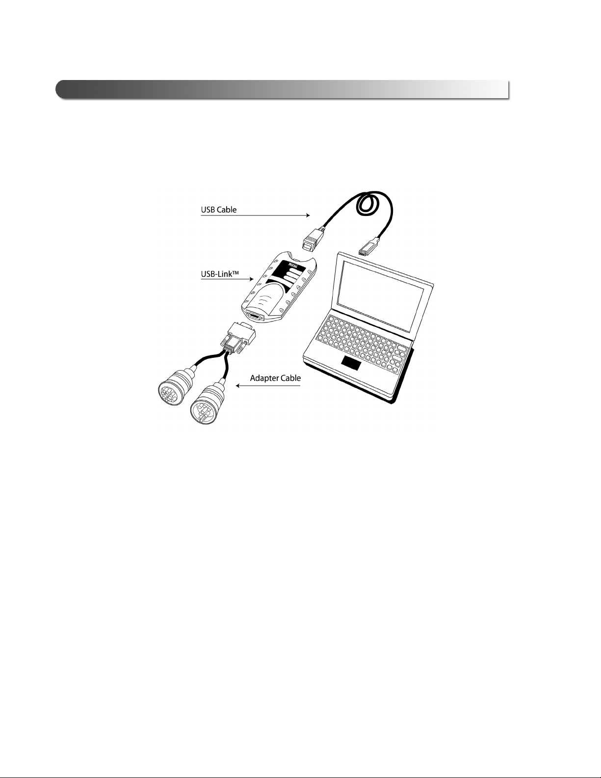
USB-Link™ Components
The following illustration details each of the USB-Link™ components:
a chapter’s first page. The page’s layout isements (e.g., ChapIntro, Body Text, Bullets, etc.), not
headings. Headings on this page produce alignment If the introduction paragraphs
a chapter’s first page. The page’s layout is designed to present body elements (e.g., ChapIntro, Body
Text, Bullets, etc.), not headings. Headings on this page produce alignment If the introduction
paragraphs
Figure 1.1 USB-Link™ Components
- Communication Options: Wireless or Wired?
USB-Link™ Installation and Setup Manual 5
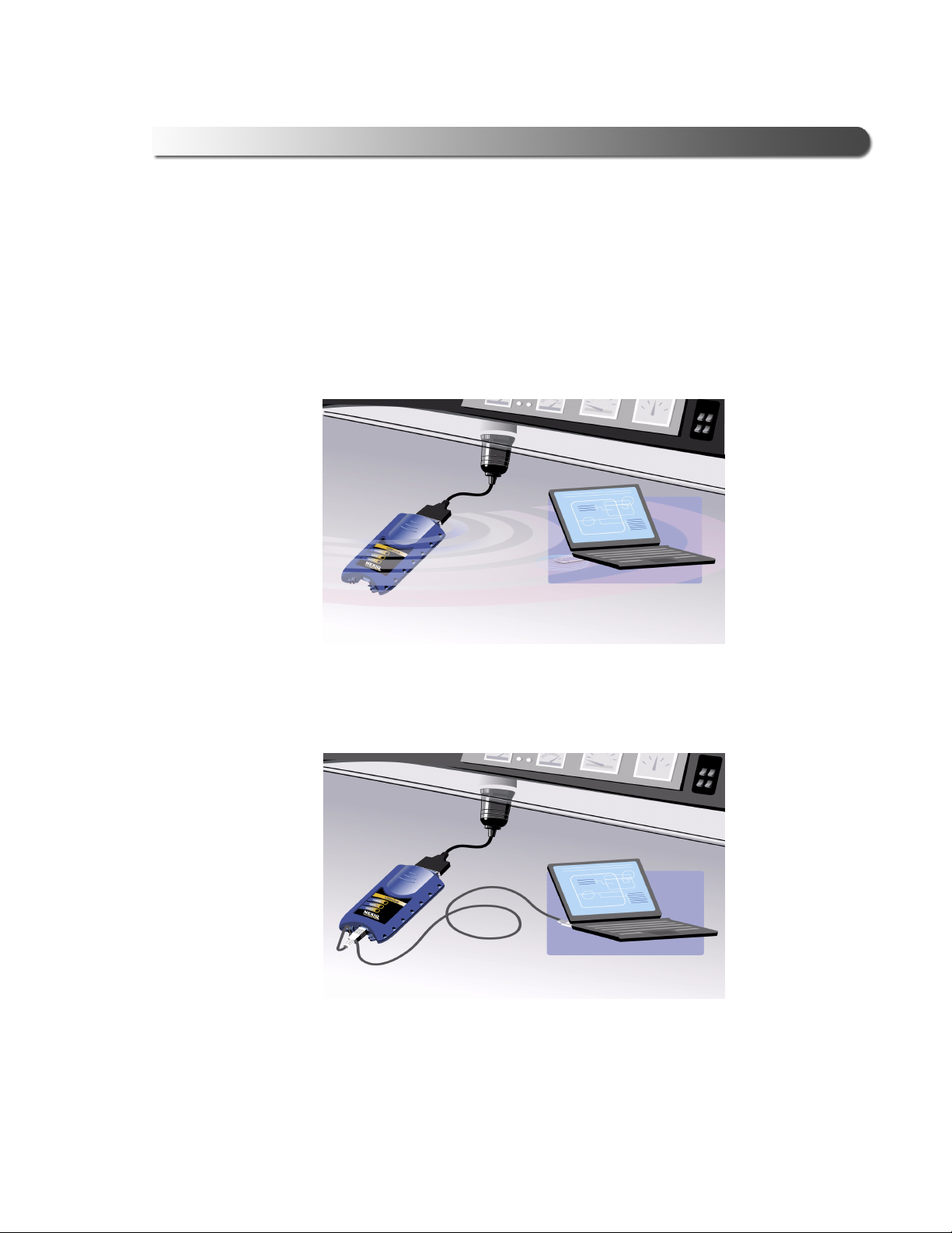
Communication Options: Wireless or Wired?
Prior to using the USB-Link™, you need to decide how you want the unit to com-
municate with your PC. There are two options:
• Wireless connection to the PC using Bluetooth
A wireless connection provides the advantage of untethered
communication.
• Wired connection to the PC using a USB cable
A wired connection provides the advantage of faster data throughput.
Figure 1.2 Wireless Connection
Figure 1.3 Wired Connection

6 USB-Link™ Installation and Setup Manual
Chapter 1• Introducing the USB-Link™
Wireless Connection
Wireless connectivity provides untethered operation, and that’s a bonus in a busy
service bay. USB-Link™ uses Bluetooth to provide this wireless communication
between the USB-Link™ and your PC.
NOTE:
iThe USB-Link™ does not support Integrated Bluetooth. If your PC has
Integrated Bluetooth, your system has Bluetooth drivers installed and a
built-in Bluetooth transceiver. You must uninstall Integrated Bluetooth and
its Bluetooth drivers prior to proceeding with the USB-Link™ installation
process.
If your PC does not have Integrated Bluetooth, then you are clear to proceed with
the USB-Link™ installation process as documented in this manual:
• Install Bluetooth drivers
• Install an external Bluetooth transceiver (i.e., an adapter)
• Configure a basic Bluetooth environment
— For detailed information on installing Bluetooth drivers and configur-
ing a basic Bluetooth environment, refer to Chapter 2: Installation and
Bluetooth Configuration, later in this manual.
• Run the NEXIQ Bluetooth Connection Utility
— For information on running the NEXIQ Bluetooth Connection Utility,
refer to Chapter 3: Preparing to Use the USB-Link™, later in this
manual.
— USB-Link™ is intended for diagnostic use, for example, retrieving
trouble codes. By nature, Bluetooth has limited bandwidth and laten-
cy when compared to wired solutions. This may result in dropped
messages in situations requiring high bandwidth.
- Communication Options: Wireless or Wired?
USB-Link™ Installation and Setup Manual 7
Wired Connection
Using a USB connection to the PC is highly recommended when diagnosing
heavily-loaded CAN/J1939 buses. By nature, Bluetooth has less bandwidth than
USB, which can result in dropped messages in situations requiring high band-
width. ECU reprogramming typically requires both high throughput and critical
timing, and should always use a USB-to-PC wired connection.
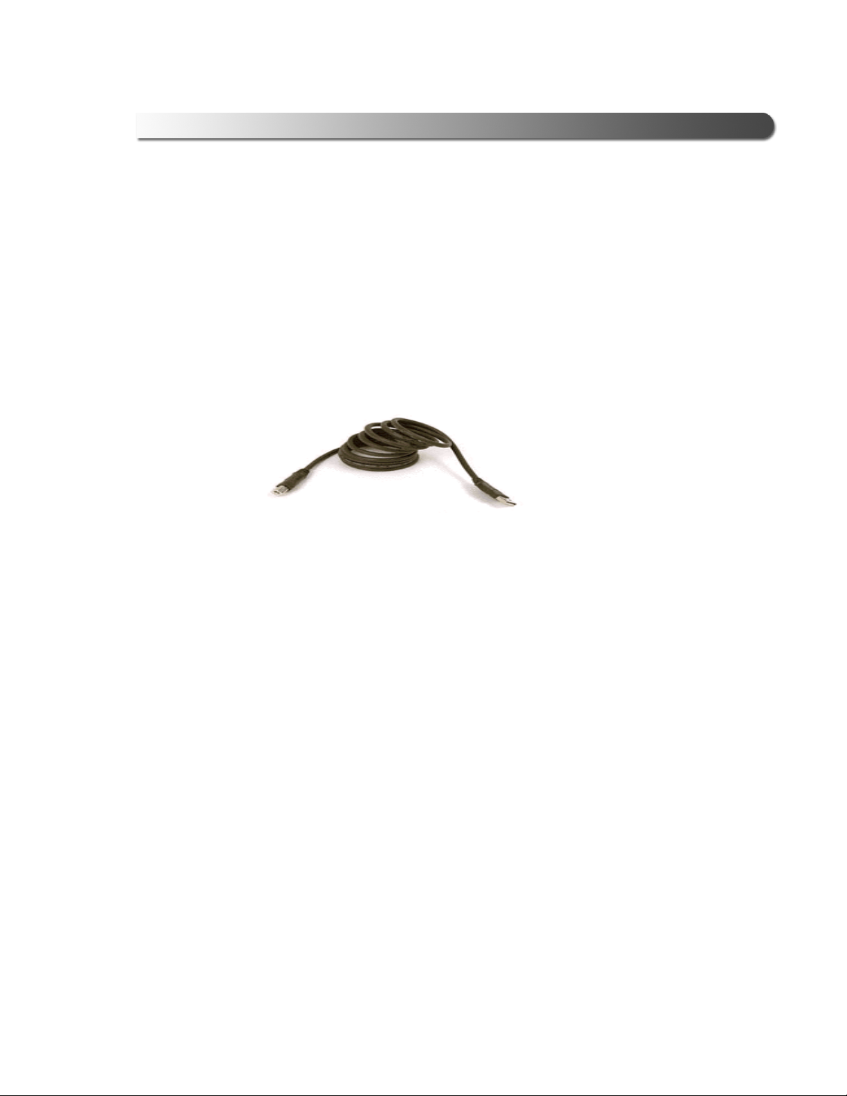
Wired communication between the USB-Link™ and your PC requires a USB
cable.
Figure 1.4 15 ft. USB Cable included with your USB-Link™

8 USB-Link™ Installation and Setup Manual
Chapter 1• Introducing the USB-Link™

USB-Link™ Installation and Setup Manual 9
2
Installation and
Bluetooth
Configuration
u
Step 1: Install the USB-Link™ Drivers and Utilities, page 12
u
Instructions for Windows® 2000 and XP Users, page 12
u
Instructions for Vista® Users, page 22
u
Step 2: Choose Your Connection, page 33
u
Step 3: Install the Bluetooth Adapter, page 35
u
Step 4: Install the Bluetooth Drivers, page 36
u
Additional Steps for Windows XP SP-2, page 44
u
Configure the Bluetooth Environment, page 52
This chapter provides instructions for installing NEXIQ drivers and utilities, installing
the required Bluetooth® drivers, installing a Bluetooth adapter, and configuring a basic
Bluetooth environment. It also provides special instructions for Vista®users.

10 USB-Link™ Installation and Setup Manual
Chapter 2• Installation and Bluetooth Configuration
Installation Process Flowchart
Figure 2.1 Process Flowchart
Install NEXIQ
Drivers
Install BT Adapter
Wireless?
Install BT Drivers
Service Pack 2
?
Update BT Drivers
Configure BT
Environment
Run Connect
Utility
Connect to Vehicle
(Physical)
Test the
Connection
Set Up Diagnostic
Applications
Yes
Yes
No
No
Connect to Vehicle
(Physical)
Other manuals for USB-Link
1
Table of contents
Other NEXIQ Technologies Diagnostic Equipment manuals

NEXIQ Technologies
NEXIQ Technologies Brake-Link Wabash National User manual

NEXIQ Technologies
NEXIQ Technologies Blue-Link 2 User manual

NEXIQ Technologies
NEXIQ Technologies Brake-Link User manual

NEXIQ Technologies
NEXIQ Technologies USB-Link 3 Wireless User guide

NEXIQ Technologies
NEXIQ Technologies Brake-Link User manual


