NEXIQ Technologies USB-Link 3 Wireless User guide
USB-Link™ 3
Installation and Setup Manual
Wireless Edition
PN 121052
Wired Edition
PN 121054

USB-Link™ 3 Installation and Setup Manual
USB-LinkTM 3: Wireless and Wired Editions
IDSC Holdings LLC retains all ownership rights to USB-Link™ 3 and its documentation. The USB-Link™ 3 source code is a condential
trade secret of IDSC Holdings LLC. You may not decipher or de-compile USB-Link™ 3, develop source code for USB-Link™ 3, or
knowingly allow others to do so. The USB-Link™ 3 and its documentation may not be sublicensed or transferred without the prior written
consent of IDSC Holdings LLC.
This manual, as well as the software it describes, is furnished under license and may only be used or copied in accordance with the
terms of such license. The content of this manual is furnished for informational use only, is subject to change without notice, and should
not be construed as a commitment by IDSC Holdings LLC. IDSC Holdings LLC assumes no responsibility or liability for any errors or
inaccuracies that may appear in this book.
Except as permitted by such license, no part of this publication may be reproduced, or transmitted, in any form or by any means,
electronic, mechanical, or otherwise, without the prior written permission of IDSC Holdings LLC.
NEXIQ Technologies and USB-Link are trademarks of IDSC Holdings LLC.
©2022 IDSC Holdings LLC. All rights reserved. All other marks are trademarks or registered trademarks of the respective holders.
Pictures for illustration purposes only. Specications are subject to change without notice.
www.nexiq.com
This device complies with Part 15 of the FCC Rules. Operation is subject to the following two conditions: (1) this device may not
cause harmful interference, and (2) this device must accept any interference received, including interference that may cause undesired
operation. This device contains FCC-ID POOWML-C30XX.
Approved in accordance to R&TTE directive transmitter module marked by “CE product label”, manufactured by MITSUMI incorporated
to OEM product.
Part No. ZEESM611AW Revised 08/10/2022

USB-Link™ 3 Installation and Setup Manual
Table of Contents
Chapter 1: Using this Manual 1
Manual Overview 2
Conventions 3
Special Messages 3
Note 3
Important 3
Caution 3
Warning 4
Troubleshooting 4
Specialized Text 4
Chapter 2: Introducing the USB-Link™ 3 5
Component Checklist 6
Product Specications 7
System Requirements 8
Device Features 9
Communication Options: Wired vs Wireless 12
Wired USB Connection 12
Wireless Bluetooth Connection 13
Wireless Wi-Fi Connection 14
Mini Access Point Mode (Peer-to-Peer) 15
Infrastructure Mode (Connecting to your Company’s Network) 16

USB-Link™ 3 Installation and Setup Manual
Table of Contents
Chapter 3: Installing the Drivers and Setting Up the Device 17
Installation Process Outline 18
Step 1: Install the Drivers 19
Step 2: Connect the USB-Link™ 3 to a Vehicle 27
Making a Wired USB Connection 28
Making a Wireless Bluetooth Connection 29
Pair the Device 30
Making a Wireless Wi-Fi Connection 32
Mini Access Point Mode 32
Infrastructure Mode 35
Step 3: Test the Connection 36
Using the USB-Link™ 3 Explorer Utility 40
The Conguration Tab 42
Switching Modes: Mini Access Point and Infrastructure 43
The File Menu 45
The Tools Menu 46
Ping 46
Options 47
The Help Menu 49

USB-Link™ 3 Installation and Setup Manual
Chapter 1:
Using this Manual
Manual Overview (pg. 2)
Conventions (pg. 3)
Special Messages (pg. 3)
Note (pg. 3)
Important (pg. 3)
Caution (pg. 3)
Warning (pg. 4)
Troubleshooting (pg. 4)
Specialized Text (pg. 4)
This chapter provides an overview of this manual’s organization and the conventions used throughout.
NOTE: Images used throughout this manual are for illustrative purposes only.
1

USB-Link™ 3 Installation and Setup Manual
Chapter 1: Using this Manual
Manual Overview
This manual provides information to support you during installation and setup of the USB-Link™ 3
Wireless Edition and Wired Edition.
This manual is composed of the following sections:
•Chapter 1: Using this Manual—provides an overview of this user manual.
• Chapter 2: Introducing the USB-Link™ 3 Wireless Edition and Wired Edition—provides details on
communication options, including Bluetooth®, Wi-Fi, USB, Mini Access Mode, and Infrastructure Mode.
• Chapter 3: Installing the Drivers and Setting up the Device—provides instructions for installing NEXIQTM
drivers and utilities, connecting to a vehicle, pairing the device, and testing the connection. It also
provides information on using the USB-Link™ 3 Explorer.
2

USB-Link™ 3 Installation and Setup Manual
Chapter 1: Using this Manual
Conventions
This section provides descriptions of the conventions used throughout this guide.
Special Messages
Note
NOTE provides an explanation, comment, or tip related to the subject matter that is being discussed.
Example:
Important
IMPORTANT indicates a situation which may damage the test equipment or vehicle.
Example:
Caution
CAUTION indicates a potentially hazardous situation which may result in minor or moderate injury to the
operator or bystanders.
Example:
NOTE: Refer to the page number indicated for further details on the described component.
IMPORTANT: Keep all cables clear of moving or hot engine parts.
CAUTION: Do not use the unit to perform tests on household or industrial sources.
3

USB-Link™ 3 Installation and Setup Manual
Chapter 1: Using this Manual
Warning
WARNING indicates a potentially hazardous situation which could result in serious injury or death to
the operator or bystanders.
Example:
Troubleshooting
Information intended to help you to address or anticipate potential issues are presented in the
following manner:
Specialized Text
The specially formatted text is used to help you to differentiate specic elements discussed within
this manual:
• Emphasis: Used to draw your attention to particularly important information.
• FEATURE: Used to highlight the name of a specic feature.
Example: “Click on the Finish button to continue.”
• Field/Line: Used to highlight the name of a eld or a line of text from a display.
Example: “A check mark is placed in the check box next to the Total Fuel Used parameter.”
• Menu Items: Used to highlight a series of menu selections.
Example: “From the Start menu, select Programs > NEXIQ > Device Tester.”
• Screen titles: Used to highlight the title of a screen displayed.
Example: “The Installation Complete screen is displayed.”
WARNING: All RP1210 adapters must be disconnected before proceeding with installation.
If NEXIQ WVL2 drivers are installed, the WVL2 Explorer Utility must be exited before proceeding
with installation.
4

USB-Link™ 3 Installation and Setup Manual
Chapter 2:
Introducing the USB-Link™3
Component Checklist (pg. 6)
Product Specications (pg. 7)
System Requirements (pg. 8)
Device Features (pg. 9)
Communication Options: Wired vs Wireless (pg. 12)
Wired USB Connection (pg. 12)
Wireless Bluetooth®Connection (pg. 13)
Wireless Wi-Fi Connection (pg. 14)
Mini Access Point Mode (Peer-to-Peer) (pg. 15)
Infrastructure Mode (Connecting to your Company’s Network) (pg. 16)
The USB-Link™ 3 is a hardware device that enables service bay technicians to use personal computers
or laptops to retrieve vehicle information using wireless Bluetooth®and Wi-Fi technologies, or a USB
cable connection. Once congured, the USB-Link™ 3 interfaces with specic PC applications to perform
vehicle diagnostics.
This chapter introduces the USB-Link™ 3 and provides details regarding the communication modes
available to interface with your PC. It also introduces the features of the USB-Link™ 3 (i.e., LEDs,
Pairing Button, USB port, Vehicle port).
5

USB-Link™ 3 Installation and Setup Manual
Chapter 2: Introducing the USB-Link™ 3
Component Checklist
The following components are included with your USB-Link™ 3. Conrm you have all of these items
before using the device:
• USB-Link™ 3
• Latching USB Cable (see Figure 2.2)
• 9-pin Deutsch Adapter, 1 Meter
• 16-pin, J1962 OBD II Adapter, 1 Meter
• Carrying Case
• USB-Link™ 3 Quick Start Guide
6
NOTE: USB-Link™ 3 drivers and this manual are available for download at the NEXIQ website:
http://nexiq.com/home/drivers

USB-Link™ 3 Installation and Setup Manual
Chapter 2: Introducing the USB-Link™ 3
Product Specications
The USB-Link™ 3 is congured with the following specications:
Feature
Physical Dimensions
Weight
Power Requirements
Operating Temperature
API Driver
Vehicle Protocols Supported
USB Communication
USB Connector
Wired Communication
Wireless Communication
Wireless Edition only
Vehicle Connector
Data
6.75” x 3.75” x 1.06”
(171 mm x 95 mm x 27 mm)
8 oz. (0.22 kg)
6 - 32 VDC @ 350 mA maximum
0 to +50 °C
TMC RP1210A, RP1210B, and RP1210C compliant
• CAN FD / J1939 FD / ISO15765 FD - 250K, 500K,
1M b/s with auto baud detection
• Single-wire CAN (SWCAN)
• ISO 11898-3 Fault Tolerant CAN (FTCAN)
• DOIP
• J1708
• J1850 VPW (Class 2)
• ISO PWM (SCP)
• ISO 9141 / KWP2000 (ISO 14230) K/L Line
• ALDL 9600 and 8192 baud
• ATEC 160 baud
USB version 2.0
Latching USB Mini-B
Automotive A to Mini-B USB cable 13 ft. (4 m) maximum
• Bluetooth®Class 1 adapter (up to 50 ft range)
• Dual band Wi-Fi (802.11 AC)
High Density D-sub 26-pin Male (HD26M)
7

USB-Link™ 3 Installation and Setup Manual
Chapter 2: Introducing the USB-Link™ 3
System Requirements
Conrm your PC meets the following system requirements:
8
Component
IBM PC-compatible computer
Operating system
Wi-Fi wireless network
Bluetooth®
Requirement
• 1GHz processor or more
• RAM: 256MB or more (512MB recommended)
• USB port, version 2.0 or higher
• Wi-Fi and/or Bluetooth
• Windows®10
• Windows®11
• Wi-Fi (802.11a, b, g, n, or AC)
• Bluetooth 2.1 or higher
USB-Link™ 3 Installation and Setup Manual
Chapter 2: Introducing the USB-Link™ 3
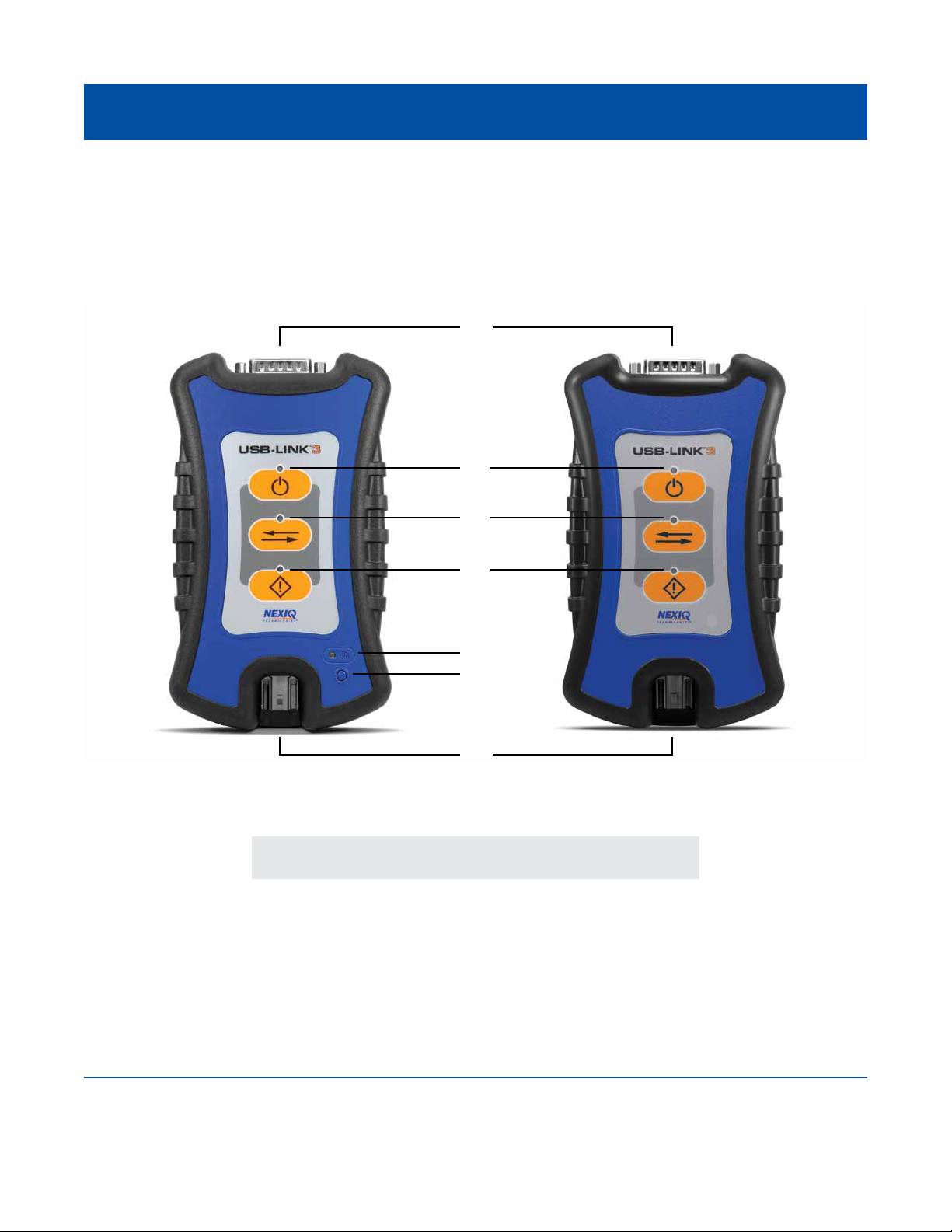
Device Features
The images below detail the features of the USB-Link™ 3 Wireless Edition and Wired Edition.
Legend
Figure 2.1 USB-Link™ 3 Wireless and Wired Edition
A – Vehicle Port
B – Power LED
C – Vehicle Data LED
D – Fault LED
E – Wireless Comm LED
F – Pairing Button
G – USB Port
9
A
G
B
C
D
E
F
Wireless Wired

USB-Link™ 3 Installation and Setup Manual
Chapter 2: Introducing the USB-Link™ 3
Device Features
These features perform the same whether in Bluetooth®or Wi-Fi mode:
The Wireless LED and the Pairing Button perform differently depending on which mode (i.e., Bluetooth®
or Wi-Fi) the device is in.
10
Feature
Vehicle Port
Power LED
Vehicle Data LED
Fault LED
USB Port
Feature
Wireless Comm LED:
Bluetooth®Mode
Wireless Comm LED:
Wi-Fi—Mini Access Point Mode
What It Does
Connects the USB-Link™ 3 to a vehicle/engine for
power and data.
Illuminates when the device receives power.
Illuminates when the device is receiving data from
the vehicle.
Illuminates when a problem is detected.
Connects the device to your PC (wired connection).
Latching USB Mini-B Connector for connection to PC host.
Not used with iOS device.
What It Does
If the device is Discoverable:
• Illuminates solid blue when connected.
• Blinks every second when not connected.
If the device is Non-Discoverable:
• Illuminates solid blue when connected.
• Off when not connected.
Mini Access Point Mode:
• Illuminates solid white when a client PC connects to
the device.
• Off when no client PC is connected.

USB-Link™ 3 Installation and Setup Manual
Chapter 2: Introducing the USB-Link™ 3
Device Features
11
Feature
Wireless Comm LED:
Wi-Fi—Infrastructure Mode
Pairing Button
Bluetooth Mode
Pairing Button
Wi-Fi Mode
What It Does
Infrastructure Mode:
• Stays off when not associated with a network
Access Point.
• Blinks every second when associated with an access
point, but no IP address assigned.
• Illuminates solid orange when successfully assigned
an IP address.
The Pairing Button is used to change the status of the
device. The two status modes are:
•Non-Discoverable—When the USB-Link™ 3 is
Non-Discoverable, it will only connect to a host device
with which it has previously been paired.
• Discoverable—When the USB-Link™ 3 is Discoverable,
a host device can detect, pair, or connect to it.
To change the mode from Non-Discoverable to
Discoverable, press and hold the Pairing button until the
Wireless LED begins to ash blue (about 3 seconds).
Once a connection is established, the LED turns solid
blue. After two minutes, discover-ability will time out, and
the device will go back to Non-Discoverable status.
When using Wi-Fi, the USB-Link™ 3 can be congured
for either of the following modes:
• Mini-Access Point (Wi-Fi default)
• Infrastructure
Note: USB-Link™ 3 cannot be used in Infrastructure
mode until it has been congured using the Explorer
utility (see Using the USB-Link™ 3 Explorer in Chapter 3
of this manual).

USB-Link™ 3 Installation and Setup Manual
Chapter 2: Introducing the USB-Link™ 3
Communication Options: Wired vs Wireless
Prior to using the USB-Link™ 3, choose how you want the unit to communicate with your PC.
There are three options:
• Wired, USB Connection (pg. 12)
• Wireless, Bluetooth®Connection (pg. 13)
• Wireless, Wi-Fi Connection (pg. 14)
Wired USB Connection
A wired USB connection provides the advantages of high data throughput, low latency, and a
high-reliability data connection.
Wired communication between the USB-Link™ 3 and your PC requires an automotive A to Mini-B USB
cable (shipped with the USB-Link™ 3).
12
NOTE: For detailed instructions on making a wired connection, refer to Making a Wired USB Connection
in Chapter 3 of this manual.
IMPORTANT: Electronic Control Module (ECU) reprogramming requires both high throughput and critical
timing, and should always use a USB-to-PC wired connection.
Figure 2.2 Automotive A to Mini-B USB Cable

USB-Link™ 3 Installation and Setup Manual
Chapter 2: Introducing the USB-Link™ 3
Wireless Bluetooth Connection
The USB-Link™ 3 can be congured to use Bluetooth®wireless technology to provide communication
between the USB-Link™ 3 and your PC. When two Bluetooth®devices are paired, a persistent link
is created between the two devices. Once congured, future connections between the devices are
authenticated automatically.
13
NOTE: For detailed instructions on conguring the USB-Link™ 3 for Bluetooth®, refer to Making a
Bluetooth Wireless Connection, in Chapter 3 of this manual.

USB-Link™ 3 Installation and Setup Manual
Chapter 2: Introducing the USB-Link™ 3
Wireless Wi-Fi Connection
The USB-Link™ 3 can be congured to use Wi-Fi to provide wireless communication between the
USB-Link™ 3 and your PC.
There are two network options:
• Mini Access Point Mode (pg. 15)
• Infrastructure Mode (pg. 16)
If you use your PC’s internal wireless network card to connect to both your company’s network and the
USB-Link™ 3, you will not have access to the Internet until you have nished your session. If you prefer
to have access to the Internet while using performing diagnostics, you will need an additional wireless
network card dedicated for use with the USB-Link™ 3.
Wi-Fi performance can be affected by network congestion, radio frequency interference, and too many
wireless devices in the vicinity. These conditions may result in dropped messages. For this reason,
wireless communication is not recommended for ECU reprogramming (i.e, reashing).
14

USB-Link™ 3 Installation and Setup Manual
Chapter 2: Introducing the USB-Link™ 3
Mini Access Point Mode (Peer-to-Peer)
The easiest and quickest way to connect your USB-Link™ 3 to your PC is with the Mini Access Point
mode. In Mini Access Point mode (also known as Access Point Emulation mode), the PC communicates
directly with the device. The USB-Link™ 3 emulates the function of an access point, allowing the PC to
connect directly to the USB-Link™ 3. When the PC is connected to the USB-Link™ 3 in Mini Access Point
mode, neither device is connected to the company network.
If you use your PC’s internal wireless network card to connect to both your company’s network and the
USB-Link™ 3, you will not have access to the Internet until you have nished your session. If you prefer
to have access to the Internet while using performing diagnostics, you will need an additional wireless
network card dedicated for use with the USB-Link™ 3.
15
Figure 2.3 Mini Access Point Mode
NOTE: For instructions on connecting the USB-Link™ 3 and your PC using Mini Access Point Mode,
see Connect Using Wi-Fi, in Chapter 3 of this manual.

USB-Link™ 3 Installation and Setup Manual
Chapter 2: Introducing the USB-Link™ 3
Infrastructure Mode (Connecting to your Company’s Network)
In Infrastructure mode, your PC communicates with your company’s computer network through a
Wireless Access Point (not included), which acts as a bridge between the wireless network and the
wired network. In this mode, the USB-Link™ 3 is congured to communicate with the same access
point. All communication between the PC and the USB-Link™ 3 passes through the access point.
16
Figure 2.4 Infrastructure Mode
NOTE: The settings for connecting to your company network may differ from one installation to another.
To ensure network security, your Information Technology (IT) administrator will need to oversee the
installation and specify the appropriate conguration parameters. Your IT administrator should be able
to properly congure the USB-Link™ 3 for infrastructure mode, using the USB-Link™ 3 Explorer utility
(see Switching Modes: Mini Access Point and Infrastructure in Chapter 3 of this manual).
This manual suits for next models
3
Table of contents
Other NEXIQ Technologies Diagnostic Equipment manuals

NEXIQ Technologies
NEXIQ Technologies Brake-Link User manual

NEXIQ Technologies
NEXIQ Technologies Brake-Link Wabash National User manual

NEXIQ Technologies
NEXIQ Technologies Blue-Link 2 User manual

NEXIQ Technologies
NEXIQ Technologies USB-Link User guide

NEXIQ Technologies
NEXIQ Technologies Brake-Link User manual


