NI cRIO-9101 User manual

USER MANUAL AND SPECIFICATIONS
NI cRIO-9101/9102/9103/9104
CompactRIO Reconfigurable Embedded Chassis
Figure 1. CompactRIO Eight-Slot and Four-Slot Reconfigurable Embedded Systems
11
24
33
1. Controller
2. Eight-Slot Reconfigurable Embedded Chassis
(cRIO-9102/9104)
3. C Series I/O Module
4. Four-Slot Reconfigurable Embedded Chassis
(cRIO-9101/9103)
This document describes how to install an NI cRIO-9101, cRIO-9102, cRIO-9103, or
cRIO-9104. In this document the NI cRIO-9101, cRIO-9102, cRIO-9103, and cRIO-9104 are
inclusively referred to as the cRIO-910x.
Safety Guidelines
Caution Do not operate the chassis in a manner not specified in this document.
Product misuse can result in a hazard. You can compromise the safety protection
built into the product if the product is damaged in any way. If the product is
damaged, return it to NI for repair.
Safety Guidelines for Hazardous Locations
The chassis is suitable for use in Class I, Division 2, Groups A, B, C, D, T4 hazardous
locations; Class I, Zone 2, AEx nA IIC T4 and Ex nA IIC T4 hazardous locations; and
nonhazardous locations only. Follow these guidelines if you are installing the chassis in a

potentially explosive environment. Not following these guidelines may result in serious injury
or death.
Caution Do not disconnect I/O-side wires or connectors unless power has been
switched off or the area is known to be nonhazardous.
Caution Do not remove modules unless power has been switched off or the area is
known to be nonhazardous.
Caution Substitution of components may impair suitability for Class I, Division 2.
Caution For Division 2 and Zone 2 applications, install the system in an enclosure
rated to at least IP54 as defined by IEC/EN 60079-15.
Special Conditions for Hazardous Locations Use in Europe and
Internationally
The chassis has been evaluated as Ex nA IIC T4 Gc equipment under DEMKO Certificate No.
03 ATEX 0324020X and is IECEx UL 14.0089X certified. Each device is marked II 3G and
is suitable for use in Zone 2 hazardous locations, in ambient temperatures of -40 °C ≤ Ta ≤
70 °C.
Caution You must make sure that transient disturbances do not exceed 140% of
the rated voltage.
Caution The system shall only be used in an area of not more than Pollution
Degree 2, as defined in IEC 60664-1.
Caution The system shall be mounted in an ATEX/IECEx-certified enclosure with
a minimum ingress protection rating of at least IP54 as defined in IEC/EN 60079-15.
Caution The enclosure must have a door or cover accessible only by the use of a
tool.
Electromagnetic Compatibility Guidelines
This product was tested and complies with the regulatory requirements and limits for
electromagnetic compatibility (EMC) stated in the product specifications. These requirements
and limits provide reasonable protection against harmful interference when the product is
operated in the intended operational electromagnetic environment.
This product is intended for use in industrial locations. However, harmful interference may
occur in some installations, when the product is connected to a peripheral device or test object,
or if the product is used in residential or commercial areas. To minimize interference with
radio and television reception and prevent unacceptable performance degradation, install and
use this product in strict accordance with the instructions in the product documentation.
2| ni.com | NI cRIO-9101/9102/9103/9104

Furthermore, any changes or modifications to the product not expressly approved by National
Instruments could void your authority to operate it under your local regulatory rules.
Special Conditions for Marine Applications
Some products are Lloyd’s Register (LR) Type Approved for marine (shipboard) applications.
To verify Lloyd’s Register certification for a product, visit ni.com/certification and search for
the LR certificate, or look for the Lloyd’s Register mark on the product.
Caution In order to meet the EMC requirements for marine applications, install the
product in a shielded enclosure with shielded and/or filtered power and input/output
ports. In addition, take precautions when designing, selecting, and installing
measurement probes and cables to ensure that the desired EMC performance is
attained.
What You Need to Install the CompactRIO
System
• CompactRIO reconfigurable embedded chassis
• CompactRIO intelligent real-time embedded controller
• C Series I/O modules
• Mounting hardware if needed (available from NI)
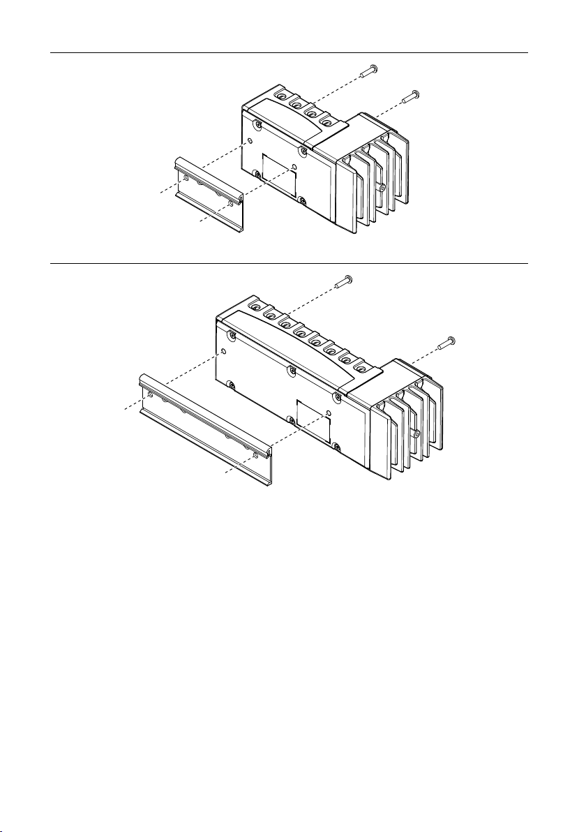
• Two M4 or number 10 panhead screws (for panel mounting only)
• Number 2 Philips screwdriver
• Power supply
• Ethernet cable
• Documentation (available on ni.com/manuals)
– cRIO controller documentation—learn how to connect the controller to a network
and configure the controller.
– C Series modules documentation—learn about module specifications and how to use
the modules.
What You Need to Start Using the CompactRIO
System
After you install the CompactRIO chassis, controller, and C Series modules, you need the
following things to start using the CompactRIO system:
• Windows computer with LabVIEW and NI-RIO software installed
•ni.com/gettingstarted—learn how to install, set up, and configure your CompactRIO
hardware and learn the basics of LabVIEW software.
•LabVIEW Help—access information about LabVIEW programming concepts, step-by-
step instructions for using LabVIEW, and reference information about LabVIEW VIs,
functions, palettes, menus, tools, properties, methods, events, dialog boxes, and so on.
NI cRIO-9101/9102/9103/9104 | © National Instruments | 3

Installing the Controller on the Chassis
Complete the following steps to install the controller on the chassis.
1. Make sure that no power is connected to the controller or the chassis.
2. Align the controller with the chassis.
Figure 2. Installing the Controller on the Chassis (Eight-Slot Chassis Shown)
1
4
3
5
2
1. Controller
2. Captive Screws
3. Controller Slot
4. Reconfigurable Embedded Chassis
5. Grounding Screw
3. Slide the controller onto the controller slot on the chassis. Press firmly to ensure the
chassis connector and the controller connector are mated.
4. Using a number 2 Phillips screwdriver, tighten the two captive screws on the front of the
controller to 1.3 N · m (11.5 lb · in.) of torque.
4| ni.com | NI cRIO-9101/9102/9103/9104

Mounting the CompactRIO Reconfigurable
Embedded Chassis
You can mount the chassis in any orientation on a 35 mm DIN rail or on a panel. Use the DIN
rail mounting method if you already have a DIN rail configuration or if you need to be able to
quickly remove the CompactRIO chassis. Use the panel mount method for high shock and
vibration applications.
Go to ni.com/info and enter the info code criomounting to learn more about the different
mounting methods for CompactRIO.
Before using any of the mounting methods, record the serial number from the back of the
chassis. You will be unable to read the serial number after you have mounted the chassis.
Caution Before you mount the chassis, make sure that I/O modules are not in the
chassis.
Caution Your installation must meet the following requirements for space and
cabling clearance:
• Allow 25.4 mm (1 in.) on the top and the bottom of the chassis for air
circulation.
• Allow 50.8 mm (2 in.) in front of modules for cabling clearance for common
connectors, such as the 10-terminal, detachable screw-terminal connector.
Go to ni.com/info and enter rdcrioconn to find the minimum cabling clearance for
C Series modules with other connector types.
Note Go to ni.com/dimensions for more information about the dimensions of the
CompactRIO system, including detailed dimensional drawings.
The following figures show the dimensions of the four- and eight-slot chassis.
NI cRIO-9101/9102/9103/9104 | © National Instruments | 5

Figure 3. Four-Slot Reconfigurable Embedded Chassis with the Controller and I/O
Modules Installed, Bottom and Side View with Dimensions
179.6 mm (7.07 in.)
Minimum
140 mm
(5.5 in.)
88.1 mm
(3.47 in.) 20.3 mm
(0.80 in.)
Cabling Clearance
50.8 mm (2 in.)
44.1 mm
(1.74 in.)
4.1 mm (0.16 in.)
44.1 mm
(1.74 in.)
63.1 mm (2.49 in.)
25 mm
(0.98 in.)
1
1. M4 Thread
Figure 4. Eight-Slot Reconfigurable Embedded Chassis with the Controller and I/O
Modules Installed, Bottom View with Dimensions
274 mm (10.79 in.)
Minimum
140 mm
(5.50 in.)
Cabling Clearance
50.8 mm (2 in.)
88.1 mm
(3.47 in.)
4.1 mm (0.16 in.)
6| ni.com | NI cRIO-9101/9102/9103/9104

Figure 5. Four-Slot Reconfigurable Embedded Chassis with the Controller Installed,
Front View with Dimensions
Cooling Outline
25.4 mm (1.0 in.)
Cooling Outline
25.4 mm (1.0 in.)
36.4 mm
(1.43 in.)
51.7 mm
(2.04 in.)
19.0 mm
(0.75 in.)
69.9 mm
(2.75 in.)
88.1 mm
(3.47 in.)
4.1 mm
(0.16 in.)
Figure 6. Eight-Slot Reconfigurable Embedded Chassis with the Controller Installed,
Front View with Dimensions
Cooling Outline
25.4 mm (1.00 in.)
Cooling Outline
25.4 mm (1.00 in.)
4.1 mm
(0.16 in.)
51.7 mm
(2.04 in.)
36.4 mm
(1.43 in.)
19.0 mm
(0.75 in.)
88.1 mm
(3.47 in.)
165.1 mm (6.50 in.)
Mounting the Chassis on a Panel
Complete the following steps to mount the chassis on a panel.
1. Align the chassis on the panel.
2. Bolt or screw the chassis to the panel using two M4 or number 10 panhead screws. NI
does not provide the screws with the chassis.
NI cRIO-9101/9102/9103/9104 | © National Instruments | 7

Figure 7. Mounting a Four-Slot Chassis on a Panel
Figure 8. Mounting an Eight-Slot Chassis on a Panel
Caution If you are using the NI 9904/9905 panel mount kit, you must use the
M4 × 22 screws included in the kit to attach the chassis to the kit.
Caution Remove the I/O modules from the chassis before removing the
chassis from the panel.
Mounting the Chassis on a DIN Rail
You can order the NI 9912 DIN rail mount kit if you want to mount a four-slot CompactRIO
chassis on a DIN rail, or the NI 9915 DIN rail mount kit if you want to mount an eight-slot
CompactRIO chassis on a DIN rail. You need one clip for mounting the chassis on a standard
35 mm DIN rail. Complete the following steps to mount the chassis on a DIN rail.
1. Fasten the DIN rail clip to the chassis using a number 2 Phillips screwdriver and two
M4 × 22 screws. The screws are included in the DIN rail mount kit.
8| ni.com | NI cRIO-9101/9102/9103/9104

Figure 9. Fastening the DIN Rail Clip to a Four-Slot Chassis
Figure 10. Fastening the DIN Rail Clip to an Eight-Slot Chassis
2. Insert one edge of the DIN rail into the deeper opening of the DIN rail clip.
NI cRIO-9101/9102/9103/9104 | © National Instruments | 9

Figure 11. Attaching the DIN Rail Clip to the DIN Rail
3
2
1
1. DIN Rail Clip
2. DIN Rail
3. DIN Rail Spring
3. Press down firmly on the chassis to compress the spring until the clip locks in place on
the DIN rail.
Caution Remove the I/O modules before removing the chassis from the DIN
rail.
Installing C Series I/O Modules in the Chassis
Figure 12. C Series I/O Module, Side and Front View with Dimensions
22.9 mm
(0.90 in.)
88.1 mm
(3.47 in.)
88.1 mm
(3.47 in.)
Note Modules with different connector types have different dimensions. Go to
ni.com/info and enter rdcrioconn for more information about the different
connector types.
Complete the following steps to install a C Series I/O module in the chassis.
1. Make sure that no I/O-side power is connected to the I/O module. If the system is in a
nonhazardous location, the chassis power can be on when you install I/O modules.
2. Align the I/O module with an I/O module slot in the chassis. The module slots are labeled
1 to 8, left to right.
10 | ni.com | NI cRIO-9101/9102/9103/9104

Figure 13. Installing an I/O Module in the Chassis (Eight-Slot Chassis Shown)
1
2
1. Insertion Groove
2. Latch
3. Squeeze the latches and insert the I/O module into the module slot.
4. Press firmly on the connector side of the I/O module until the latches lock the I/O module
into place.
5. Repeat these steps to install additional I/O modules.
Removing I/O Modules from the Chassis
Complete the following steps to remove a C Series I/O module from the chassis.
1. Make sure that no I/O-side power is connected to the I/O module. If the system is in a
nonhazardous location, the chassis power can be on when you remove I/O modules.
2. Squeeze the latches on both sides of the module and pull the module out of the chassis.
Connecting the Chassis to Earth Ground
You must connect the panhead screw at the end of the chassis to ground using shielded cables.
NI cRIO-9101/9102/9103/9104 | © National Instruments | 11

Where to Go from Here
Visit ni.com/compactriodevguide for an overview of programming practices and examples for
your CompactRIO system.
Specifications
The following specifications are typical for the range -40 °C to 70 °C unless otherwise noted.
These specifications are for the reconfigurable embedded chassis only. For the controller and
I/O module specifications, refer to the operating instructions for the controller and I/O
modules you are using.
Reconfigurable FPGA
cRIO-9101 and cRIO-9102
Number of logic slices 5,120
Equivalent number 11,520
Available embedded RAM 81,920 bytes
cRIO-9103 and cRIO-9104
Number of logic slices 14,336
Equivalent number 32,256
Available embedded RAM 196,608 bytes
Timebases (40, 80, 120, 160, or 200 MHz)
Accuracy ±100 ppm maximum
Frequency dependent jitter
40 MHz 250 ps
80 MHz 980 ps
120 MHz 970 ps
160 MHz 960 ps
200 MHz 950 ps
Power Requirements
These power requirements are for a fully loaded chassis and exclude the power requirements
of the controller and the I/O modules in the chassis. For more information about the controller
12 | ni.com | NI cRIO-9101/9102/9103/9104

and the I/O module power requirements, refer to the controller and module documentation on
ni.com/manuals.
Chassis power consumption/dissipation
cRIO-9101 and cRIO-9102
+5 VDC 500 mW maximum
+3.3 VDC 1,800 mW maximum
Total chassis power consumption 2,300 mW maximum
cRIO-9103 and cRIO-9104
+5 VDC 500 mW maximum
+3.3 VDC 2,500 mW maximum
Total chassis power consumption 3,000 mW maximum
Note The power consumption specifications in this document are maximum values
for a LabVIEW FPGA application compiled at 40 MHz. Visit ni.com/info and enter
the Info Code rdcriotemp for more information about the cRIO-910x power
consumption and to help you understand your application power requirements.
Physical Characteristics
If you need to clean the chassis, wipe it with a dry towel.
Weight
cRIO-9101 and cRIO-9103 Approx. 490 g (17.3 oz)
cRIO-9102 and cRIO-9104 Approx. 790 g (28 oz)
Environmental
Operating temperature
(IEC 60068-2-1, IEC 60068-2-2)
-40 °C to 70 °C
Caution For some applications, the operating temperature for the cRIO-910x is
derated. Visit ni.com/info and enter the Info Code rdcriotemp for more
information about the cRIO-910x operating temperature and mounting
specifications.
Storage temperature
(IEC 60068-2-1, IEC 60068-2-2)
-40 °C to 85 °C
Ingress protection IP40
Operating humidity (IEC 60068-2-78) 10% RH to 90% RH, noncondensing
Storage humidity (IEC 60068-2-78) 5% RH to 95% RH, noncondensing
NI cRIO-9101/9102/9103/9104 | © National Instruments | 13

Pollution Degree (IEC 60664) 2
Maximum altitude 5,000 m
Indoor use only.
Shock and Vibration
To meet these specifications, you must panel mount the CompactRIO system and affix ferrules
to the ends of the terminal lines.
Operating vibration
Random (IEC 60068-2-64) 5 grms, 10 Hz to 500 Hz
Sinusoidal (IEC 60068-2-6) 5 g, 10 Hz to 500 Hz
Operating shock (IEC 60068-2-27) 30 g, 11 ms half sine; 50 g, 3 ms half sine;
18 shocks at 6 orientations
Hazardous Locations
U.S. (UL) Class I, Division 2, Groups A, B, C, D, T4;
Class I, Zone 2, AEx nA IIC T4
Canada (C-UL) Class I, Division 2, Groups A, B, C, D, T4;
Class I, Zone 2, Ex nA IIC T4
Europe (ATEX) and International (IECEx) Ex nA IIC T4 Gc
Safety and Hazardous Locations Standards
This product is designed to meet the requirements of the following electrical equipment safety
standards for measurement, control, and laboratory use:
• IEC 61010-1, EN 61010-1
• UL 61010-1, CSA 61010-1
• EN 60079-0:2012, EN 60079-15:2010
• IEC 60079-0: Ed 6, IEC 60079-15; Ed 4
• UL 60079-0; Ed 5, UL 60079-15; Ed 3
• CSA 60079-0:2011, CSA 60079-15:2012
Note For UL and other safety certifications, refer to the product label or the Online
Product Certification section.
14 | ni.com | NI cRIO-9101/9102/9103/9104

Electromagnetic Compatibility
Emissions EN 55011 Class A at 10 m FCC Part 15A
above 1 GHz
Immunity Industrial levels per EN 61326-1:1997 +
A2:2001, Table A.1
EMC/EMI CE, C-Tick, and FCC Part 15 (Class A)
Compliant
Note For EMC compliance, you must operate this device with shielded cabling.
The device must be connected to earth ground.
Related Information
Connecting the Chassis to Earth Ground on page 11
CE Compliance
This product meets the essential requirements of applicable European Directives, as follows:
• 2014/35/EU; Low-Voltage Directive (safety)
• 2014/30/EU; Electromagnetic Compatibility Directive (EMC)
• 94/9/EC; Potentially Explosive Atmospheres (ATEX)
Online Product Certification
Refer to the product Declaration of Conformity (DoC) for additional regulatory compliance
information. To obtain product certifications and the DoC for this product, visit ni.com/
certification, search by model number or product line, and click the appropriate link in the
Certification column.
Environmental Management
NI is committed to designing and manufacturing products in an environmentally responsible
manner. NI recognizes that eliminating certain hazardous substances from our products is
beneficial to the environment and to NI customers.
For additional environmental information, refer to the Minimize Our Environmental Impact
web page at ni.com/environment. This page contains the environmental regulations and
directives with which NI complies, as well as other environmental information not included in
this document.
Waste Electrical and Electronic Equipment (WEEE)
EU Customers At the end of the product life cycle, all NI products must be
disposed of according to local laws and regulations. For more information about
how to recycle NI products in your region, visit ni.com/environment/weee.
NI cRIO-9101/9102/9103/9104 | © National Instruments | 15

Worldwide Support and Services
The NI website is your complete resource for technical support. At ni.com/support, you have
access to everything from troubleshooting and application development self-help resources to
email and phone assistance from NI Application Engineers.
Visit ni.com/services for NI Factory Installation Services, repairs, extended warranty, and
other services.
Visit ni.com/register to register your NI product. Product registration facilitates technical
support and ensures that you receive important information updates from NI.
A Declaration of Conformity (DoC) is our claim of compliance with the Council of the
European Communities using the manufacturer’s declaration of conformity. This system
affords the user protection for electromagnetic compatibility (EMC) and product safety. You
can obtain the DoC for your product by visiting ni.com/certification. If your product supports
calibration, you can obtain the calibration certificate for your product at ni.com/calibration.
NI corporate headquarters is located at 11500 North Mopac Expressway, Austin, Texas,
78759-3504. NI also has offices located around the world. For telephone support in the United
States, create your service request at ni.com/support or dial 1 866 ASK MYNI (275 6964). For
telephone support outside the United States, visit the Worldwide Offices section of ni.com/
niglobal to access the branch office websites, which provide up-to-date contact information,
support phone numbers, email addresses, and current events.
Refer to the NI Trademarks and Logo Guidelines at ni.com/trademarks for information on NI trademarks. Other product and
company names mentioned herein are trademarks or trade names of their respective companies. For patents covering NI
products/technology, refer to the appropriate location: Help»Patents in your software, the patents.txt file on your media, or the
National Instruments Patent Notice at ni.com/patents. You can find information about end-user license agreements (EULAs)
and third-party legal notices in the readme file for your NI product. Refer to the Export Compliance Information at ni.com/
legal/export-compliance for the NI global trade compliance policy and how to obtain relevant HTS codes, ECCNs, and other
import/export data. NI MAKES NO EXPRESS OR IMPLIED WARRANTIES AS TO THE ACCURACY OF THE INFORMATION
CONTAINED HEREIN AND SHALL NOT BE LIABLE FOR ANY ERRORS. U.S. Government Customers: The data contained in
this manual was developed at private expense and is subject to the applicable limited rights and restricted data rights as set forth
in FAR 52.227-14, DFAR 252.227-7014, and DFAR 252.227-7015.
© 2004—2015 National Instruments. All rights reserved.
371559C-01 Oct15
This manual suits for next models
3
Table of contents
Other NI Chassis manuals