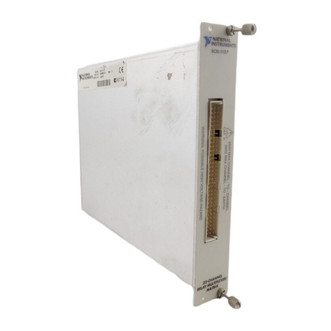
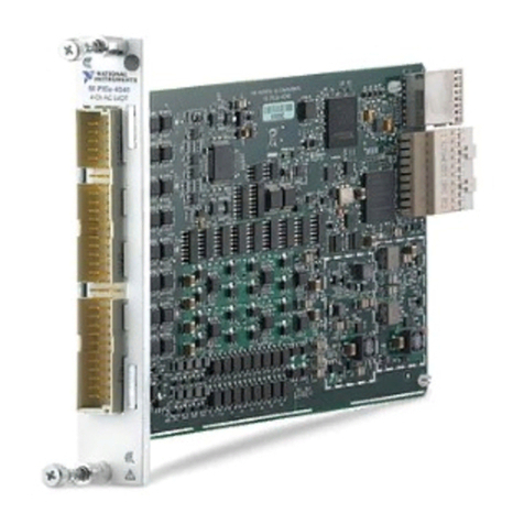
NI GPIB-410 User manual

© Copyright 1986,1994 National Instruments Corporation.
All Rights Reserved.
GPIB-410
User Manual
March 1994 Edition
Part Number 320053-01

National Instruments Corporate Headquarters
6504 Bridge Point Parkway
Austin, TX 78730-5039
(512) 794-0100
Technical support fax: (800) 328-2203
(512) 794-5678
Branch Offices:
Australia (03) 879 9422, Austria (0662) 435986, Belgium 02/757.00.20,
Canada (Ontario) (519) 622-9310, Canada (Québec) (514) 694-8521,
Denmark 45 76 26 00, Finland (90) 527 2321, France (1) 48 14 24 24,
Germany 089/741 31 30, Italy 02/48301892, Japan (03) 3788-1921,
Mexico 95 800 010 0793, Netherlands 03480-33466, Norway 32-84 84 00,
Singapore 2265886, Spain (91) 640 0085, Sweden 08-730 49 70,
Switzerland 056/20 51 51, Taiwan 02 377 1200, U.K. 0635 523545

Limited Warranty
The GPIB-410 is warranted against defects in materials and workmanship
for a period of two years from the date of shipment, as evidenced by
receipts or other documentation. National Instruments will, at its option,
repair or replace equipment that proves to be defective during the warranty
period. This warranty includes parts and labor.
The media on which you receive National Instruments software are
warranted not to fail to execute programming instructions, due to defects in
materials and workmanship, for a period of 90 days from date of shipment,
as evidenced by receipts or other documentation. National Instruments will,
at its option, repair or replace software media that do not execute
programming instructions if National Instruments receives notice of such
defects during the warranty period. National Instruments does not warrant
that the operation of the software shall be uninterrupted or error free.
A Return Material Authorization (RMA) number must be obtained from the
factory and clearly marked on the outside of the package before any
equipment will be accepted for warranty work. National Instruments will
pay the shipping costs of returning to the owner parts which are covered by
warranty.
National Instruments believes that the information in this manual is
accurate. The document has been carefully reviewed for technical accuracy.
In the event that technical or typographical errors exist, National
Instruments reserves the right to make changes to subsequent editions of
this document without prior notice to holders of this edition. The reader
should consult National Instruments if errors are suspected. In no event
shall National Instruments be liable for any damages arising out of or
related to this document or the information contained in it.
EXCEPT AS SPECIFIED HEREIN, NATIONAL INSTRUMENTS MAKES NO
WARRANTIES, EXPRESS OR IMPLIED, AND SPECIFICALLY DISCLAIMS
ANY WARRANTY OF MERCHANTABILITY OR FITNESS FOR A
PARTICULAR PURPOSE. CUSTOMER’S RIGHT TO RECOVER DAMAGES
CAUSED BY FAULT OR NEGLIGENCE ON THE PART OF NATIONAL
INSTRUMENTS SHALL BE LIMITED TO THE AMOUNT THERETOFORE
PAID BY THE CUSTOMER. NATIONAL INSTRUMENTS WILL NOT BE
LIABLE FOR DAMAGES RESULTING FROM LOSS OF DATA, PROFITS,
USE OF PRODUCTS, OR INCIDENTAL OR CONSEQUENTIAL DAMAGES,
EVEN IF ADVISED OF THE POSSIBILITY THEREOF. This limitation of the
liability of National Instruments will apply regardless of the form of action,
whether in contract or tort, including negligence. Any action against

National Instruments must be brought within one year after the cause of
action accrues. National Instruments shall not be liable for any delay in
performance due to causes beyond its reasonable control. The warranty
provided herein does not cover damages, defects, malfunctions, or service
failures caused by owner’s failure to follow the National Instruments
installation, operation, or maintenance instructions; owner’s modification of
the product; owner’s abuse, misuse, or negligent acts; and power failure or
surges, fire, flood, accident, actions of third parties, or other events outside
reasonable control.
Copyright
Under the copyright laws, this publication may not be reproduced or
transmitted in any form, electronic or mechanical, including photocopying,
recording, storing in an information retrieval system, or translating, in
whole or in part, without the prior written consent of National Instruments
Corporation.
Trademarks
Product and company names listed are trademarks or trade names of their
respective companies.
WARNING REGARDING MEDICAL AND
CLINICAL USE OF
NATIONAL INSTRUMENTS PRODUCTS
National Instruments products are not designed with components and testing
intended to ensure a level of reliability suitable for use in treatment and
diagnosis of humans. Applications of National Instruments products
involving medical or clinical treatment can create a potential for accidental
injury caused by product failure, or by errors on the part of the user or
application designer. Any use or application of National Instruments
products for or involving medical or clinical treatment must be performed by
properly trained and qualified medical personnel, and all traditional medical
safeguards, equipment, and procedures that are appropriate in the particular
situation to prevent serious injury or death should always continue to be
used when National Instruments products are being used. National
Instruments products are NOT intended to be a substitute for any form of
established process, procedure, or equipment used to monitor or safeguard
human health and safety in medical or clinical treatment.

© National Instruments Corp. v GPIB-410 User Manual
Contents
About This Manual ..........................................................................xi
Organization of This Manual......................................................xi
Conventions Used in This Manual .............................................xiii
Abbreviations ...............................................................xiv
Acronyms .....................................................................xiv
Related Document ......................................................................xv
Customer Communication ..........................................................xv
Chapter 1
Introduction.........................................................................................1-1
What Your Kit Contains.............................................................1-2
Optional Equipment....................................................................1-3
Unpacking Your GPIB-410 ........................................................1-3
Hardware Specifications.............................................................1-4
Software Specifications ..............................................................1-4
Chapter 2
Hardware and Software Installation ........................................2-1
Step 1 – Configure the Hardware ...........................................2-1
Step 2 – Install the Hardware .................................................2-2
Step 3 – Review the Files on the Distribution Diskette..........2-4
Step 4 – Run the Hardware Diagnostics.................................2-5
Chapter 3
Software Overview...........................................................................3-1
The Monitor Window .................................................................3-3
The Analyzer Window ...............................................................3-4
Screens of the Analyzer Window ...............................................3-5
Capture Settings Screen ...............................................3-5
Trigger Specification Screen ........................................3-6
Capture Display Screen ................................................3-6
Pattern Generator Screen..............................................3-6
Configuration Settings Screen .....................................3-6
Help Utility Screen.......................................................3-7
Program Exit Screen.....................................................3-7
Operational Modes and Functions ..............................................3-8
<Alt-C> Capture...........................................................3-8
<Alt-E> Capture Echo .................................................3-8

Contents
GPIB-410 User Manual vi © National Instruments Corp.
<Alt-R> Recapture.......................................................3-9
<Alt-T> Trigger ...........................................................3-9
<Alt-G> Generate.........................................................3-9
<Alt-M> Monitor Input................................................3-9
<Alt-A> Acceptor Handshaker ....................................3-10
<Alt-S> Source Handshaker......................................... 3-10
<Alt-D> DOS Shell......................................................3-10
<Alt-I> DOS Shell + Icon ............................................3-10
General Input Conventions.........................................................3-11
Direct Input Fields ....................................................... 3-12
Option Ring Fields .......................................................3-13
Key Select Fields ......................................................... 3-13
Chapter 4
Software Reference...........................................................................4-1
The Monitor Window .................................................................4-1
Data Line Input (Character) .........................................4-3
Data Line Input (Hexadecimal)....................................4-3
Data and Control Line Input (Binary) ..........................4-3
The Capture Settings Screen.......................................................4-4
Capture Stimulus ..........................................................4-5
Participate in Handshake ..............................................4-7
Buffer Setup: Maximum Capacity ..............................4-7
Buffer Setup: Action When Buffer Full ......................4-7
Buffer Setup: Auto-Write Each Pass...........................4-8
File Setup: Buffer Range for <Alt-W> .......................4-8
File Setup: Capture File Name ....................................4-9
The Trigger Specification Screen ...............................................4-9
Data/Control Specification (Trigger Pattern)...............4-12
Pattern Repetition Factor .............................................4-12
Pulse Output Port .........................................................4-12
Trigger Action ..............................................................4-13
The Capture Display Screen.......................................................4-14
Display Window Layout ..............................................4-15
Using the Display Window ..........................................4-18
Using the Search Utility ...............................................4-19
The Pattern Generator Screen.....................................................4-20
No. of Times to Execute...............................................4-22
Clear Switches When Done .........................................4-22
Send EOI with Last Byte .............................................4-22
Pattern Buffer Source...................................................4-23
The Configuration Settings Screen.............................................4-25
Computer Display Mode ..............................................4-26

Contents
© National Instruments Corp. vii GPIB-410 User Manual
Computer Keyboard Mode...........................................4-27
Computer Speaker Mode .............................................4-28
Base I/O Address ......................................................... 4-28
Input DMA Channel.....................................................4-28
Output DMA Channel ..................................................4-29
Interrupt Jumper Setting...............................................4-30
Status Refresh Rate ......................................................4-30
Acceptor Handshake Rate ............................................4-31
Source Handshake Rate ............................................... 4-31
Help File Name ............................................................4-32
Program Exit Screen...................................................................4-32
Save Current Configuration Before Exiting?...............4-33
Appendix A
Tutorial .................................................................................................A-1
Example 1 – Capturing Data From the GPIB.........................A-1
Example 2 – Triggering and Pattern Generating ....................A-7
Appendix B
Multiline Interface Messages .......................................................B-1
Appendix C
Hardware and Software Configuration...................................C-1
Hardware – Revision B.2 or Higher........................................C-1
Base I/O Address Configuration ..................................C-2
DMA Channel Configuration.......................................C-5
Interrupt Selection ........................................................C-8
Hardware – Revision C ........................................................... C-10
Base I/O Address Configuration ..................................C-11
DMA Channel Configuration.......................................C-13
Interrupt Selection ........................................................C-16
Software Configuration ..............................................................C-18
Appendix D
Common Problems...........................................................................D-1
Appendix E
Using the Pattern Generator........................................................E-1
The Command File Method........................................................E-1
IBPGL Command Descriptions ...................................E-2
IBPGL Tips and Techniques ........................................E-6

Contents
GPIB-410 User Manual viii © National Instruments Corp.
The Input Window Method ........................................................E-7
Appendix F
GPIB410.PAT Source Listing......................................................F-1
Appendix G
Saving and Viewing Capture Information on Disk.............G-1
Appendix H
Differences between Software Revisions.................................H-1
Important Differences.................................................................H-1
Feature Highlights ......................................................................H-2
Appendix I
Customer Communication............................................................I-1
Index................................................................................................Index-1
Figures
Figure 1-1. GPIB-410 Interface Board.................................................1-1
Figure 2-2. BNC I/O Panel and Cables Connected to the GPIB-410
Interface Board Installed in an IBM Compatible
Computer ...........................................................................2-4
Figure 3-1. Monitor/Analyzer Main Menu Screen...............................3-1
Figure 3-2. Monitor Window ...............................................................3-2
Figure 3-3. Analyzer Window ..............................................................3-2
Figure 3-4. GPIB Status Indicators.......................................................3-3
Figure 3-5. Format of the Analyzer Window .......................................3-4
Figure 3-6. DOS Shell with GPIB-410 Icon.........................................3-11
Figure 4-1. Monitor Window at the Top of the Screen ........................4-1
Figure 4-2. Capture Settings Screen.....................................................4-4
Figure 4-3. Trigger Specification Screen .............................................4-10
Figure 4-4. Capture Display Screen .....................................................4-14
Figure 4-5. Search Pattern Definition Window ....................................4-19
Figure 4-6. Pattern Generator Screen ................................................... 4-20
Figure 4-7. Configuration Settings Screen ........................................... 4-25
Figure 4-8. Program Exit Screen ..........................................................4-32

Contents
© National Instruments Corp. ix GPIB-410 User Manual
Figure A-1. Main Screen .......................................................................A-2
Figure A-2. Capture Settings Screen.....................................................A-3
Figure A-3. Main Menu Screen with Monitor Input and Capturing
Enabled ..............................................................................A-4
Figure A-4. Capture Display Screen .....................................................A-6
Figure A-5. Pattern Generator Screen ...................................................A-7
Figure A-6. Trigger Specification Screen .............................................A-10
Figure A-7. Main Menu Screen with Trigger Enabled .........................A-11
Figure A-8. Captured Data Including Trigger Point ............................. A-12
Figure C-1. GPIB-410 Parts Locator Diagram (Rev. B.2 or Higher) ...C-2
Figure C-2. Base I/O Address 300 Hex (Rev. B.2 or Higher) ..............C-4
Figure C-3. Factory Default DMA Channel 1 (Rev. B.2 or Higher) ....C-6
Figure C-4. DMA Channel Jumper Settings for DMA Channels 2
and 3 (Rev. B.2 or Higher).................................................C-7
Figure C-5. Factory Default IRQ Line 7 Selected (Rev. B.2 or
Higher)...............................................................................C-8
Figure C-6. IRQ Lines 6 and 2 Selected (Rev. B.2 or Higher) .............C-8
Figure C-7. GPIB-410 Parts Locator Diagram (Rev. C).......................C-10
Figure C-8. Base I/O Address 300 Hex (Rev. C)..................................C-12
Figure C-9. Factory Default DMA Channel 1 (Rev. C)........................C-14
Figure C-10. DMA Channel 1 for Capturing and DMA Channel 3 for
Sourcing (Rev. C) ..............................................................C-15
Figure C-11. DMA Channel 1 for Capturing and no DMA Channel for
Sourcing (Rev. C) ..............................................................C-15
Figure C-12. Factory Default IRQ Line 7 Selected (Rev. C)..................C-16
Figure C-13. IRQ Lines 6 and 2 Selected (Rev. C).................................C-17
Figure C-14. Configuration Settings Screen ...........................................C-18
Figure G-1. FMT410 Output Listing.....................................................G-3
Figure G-2. Abbreviated FMT410 Output Listing ................................G-5
Tables
Table C-1. DMA Channels for the GPIB-410 (Rev. B.2 or Higher)...C-5
Table C-2. DMA Channels for the GPIB-410 (Rev. C).......................C-13
Table G-1. Run-Time Flags .................................................................G-4

© National Instruments Corp. xi GPIB-410 User Manual
About This Manual
This manual contains the information you need to configure and install the
GPIB-410. It also contains a brief tutorial to get you started and a few
examples to show how the GPIB-410 operates.
This manual is applicable to:
• Revision C of the GPIB-410 software
• Revision B.2 or higher and Revision C of the GPIB-410 hardware
Refer to Appendix H for a description of the differences between software
revisions. Refer to Appendix C for a description of the differences between
hardware Revision B.2 or higher and Revision C.
Organization of This Manual
This manual is organized as follows:
• Chapter 1, Introduction, contains a list of the kit contents and optional
equipment and the steps for unpacking your GPIB-410 interface board.
It also contains general information about the GPIB-410 and lists the
specifications of the hardware and software.
• Chapter 2, Hardware and Software Installation, contains the steps for
installing your hardware and software.
• Chapter 3, Software Overview, contains general information about the
GPIB-410 software, including an introduction to the two windows of
operation (monitor and analyzer). There is also an overview of the
menu screens and operational modes, and the input conventions used in
the software.
• Chapter 4, Software Reference, contains reference material for the
GPIB-410 software. It contains information about the Monitor window
and the various screens of the Analyzer window, and their respective
input fields.

About This Manual
GPIB-410 User Manual xii © National Instruments Corp.
• Appendix A, Tutorial, contains examples that guide you through
step-by-step demonstrations of some fundamental capabilities of the
GPIB-410.
• Appendix B, Multiline Interface Messages, contains an interface
message reference list, which describes the mnemonics and messages
that correspond to the interface functions.
• Appendix C, Hardware and Software Configuration, describes how to
reconfigure the GPIB-410 hardware and software.
• Appendix D, Common Problems, contains possible causes for common
problems encountered when operating the GPIB-410.
• Appendix E, Using the Pattern Generator, describes the Interface Bus
Pattern Generating Language (IBPGL) and syntax conventions for
data/command strings.
• Appendix F, GPIB410.PAT Source Listing, contains a source listing of
the IBPGL example program, GPIB410.PAT.
• Appendix G, Saving and Viewing Capture Information on Disk,
describes saving and viewing capture buffers on disk. Also included is
a description of the FMT410 utility.
• Appendix H, Differences Between Software Revisions, describes the
differences between major software revisions.
• Appendix I, Customer Communication, contains forms for you to
complete to facilitate communication with National Instruments
concerning our products.
• The Index contains an alphabetical list of key terms and topics used in this
manual, including the page where each one can be found.

About This Manual
© National Instruments Corp. xiii GPIB-410 User Manual
Conventions Used in This Manual
The following conventions are used to distinguish elements of text
throughout this manual:
italic Italic text denotes emphasis, a cross reference, or
an introduction to a key concept.
monospace Lowercase text in this font denotes text or
characters that are to be literally input from the
keyboard, sections of code, programming
examples, and syntax examples. This font is also
used for the proper names of disk drives, paths,
directories, programs, subprograms, subroutines,
device names, functions, variables, filenames,
and extensions, and for statements and comments
taken from program code.
bold monospace Bold lowercase text in this font denotes the
messages and responses that the computer
automatically prints to the screen.
italic monospace
Italic lowercase text in this font denotes that you
must supply the appropriate words or values in
the place of these items.
<> Angle brackets enclose the name of a key on the
keyboard–for example, <PgDn>.
- A hyphen between two or more key names
enclosed in angle brackets denotes that you
should simultaneously press the named keys–for
example, <Ctrl-Alt-Del>.
<Ctrl> Key names are capitalized.

About This Manual
GPIB-410 User Manual xiv © National Instruments Corp.
Abbreviations
The following are the abbreviations for units of measure used in this
manual:
A ampere
C Celsius
°degree
Hz hertz
hex hexadecimal
in. inch
K kilobytes
KHz kilohertz
MHz megahertz
nsec nanosecond
% percent
V volt
Acronyms
The following acronyms are used in this manual:
ANSI American National Standards Institute
ASCII American Standard Code for Information Interchange
BNC referring to a coaxial connector
DMA direct memory access
FIFO first in, first out (referring to a memory buffer)
GPIB General Purpose Interface (IEEE-488) Bus
IEEE-488 Institute of Electrical and Electronic Engineers
Standard 488-1978, which defines the GPIB
I/O input/output
IRQ interrupt request line
LED light-emitting diode
PIO programmed I/O
RAM random-access memory
ROM read-only memory

About This Manual
© National Instruments Corp. xv GPIB-410 User Manual
Related Document
The following document contains information that you may find helpful as
you read this manual:
ANSI/IEEE Std 488-1978, IEEE Standard Digital Interface for
Programmable Instrumentation
Customer Communication
We appreciate communicating with the people who use our products. We
are also very interested in hearing about the applications you develop using
our products. To make it easy for you to communicate with us, this manual
contains forms for you to complete. These forms are located in Appendix I,
Customer Communication, at the back of this manual.

© National Instruments Corp. 1-1 GPIB-410 User Manual
Chapter 1
Introduction
This chapter contains a list of the kit contents and optional equipment
and the steps for unpacking your GPIB-410 interface board. It also
contains general information about the GPIB-410 and lists the
specifications of the hardware and software.
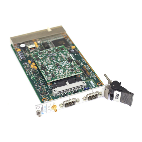
The National Instruments GPIB-410 interface board (shown in Figure 1-
1) transforms a personal computer into a sophisticated IEEE-488 bus
monitor and analyzer. The GPIB-410 has low-level testing and
debugging capabilities as well as high-level analysis tools.
Figure 1-1. GPIB-410 Interface Board
The GPIB-410 displays the complete status of the GPIB on the screen at
all times. With sixteen simulated LEDs, one for each GPIB signal, you
receive real-time, visual information about GPIB activity.
You can use the GPIB-410 to directly interact with the GPIB through the
PC keyboard. The sixteen simulated switches can be toggled on and off
from the keyboard to assert or unassert each GPIB signal. This low-

Introduction Chapter 1
GPIB-410 User Manual 1-2 © National Instruments Corp.
level control is useful for manually debugging GPIB activity. In
addition, these switches can be manipulated automatically at high
speed by the Pattern Generator utility when real-time testing and
simulation are required.
The GPIB-410 has high-level GPIB analysis tools. It can capture large
amounts of information from the GPIB at full speed, without interfering
with GPIB activity. This capture of GPIB status can be related to
specific user-selectable GPIB events, a user-selectable internal clock
rate, or an external clock input. This information is then interpreted in a
high-level format. You can browse or pattern search through the
captured data directly on the screen, log it to a disk, and obtain a
printed output copy. With multiple-level triggering, you can trigger on a
pattern or sequence of patterns on the GPIB. This triggering feature is
useful in focusing on a particular range of activity for capture.
What Your Kit Contains
Your kit should contain the following components:
Component Part Number
GPIB-410 Interface Board 180280-01
BNC I/O Panel with Two Input/Output Cables 180285-01
5.25 in. Distribution Disk for GPIB-410 GPIB 420302-10
Monitor/Analyzer Software
or
3.5 in. Distribution Disk for GPIB-410 GPIB 422302-10
Monitor/Analyzer Software
GPIB-410 User Manual 320053-01
Make sure each of these items is in your kit. If any item is missing,
contact National Instruments.

Chapter 1 Introduction
© National Instruments Corp. 1-3 GPIB-410 User Manual
Optional Equipment
Equipment Part Number
Single-Shielded GPIB Cables:
Type X1 Cable – 1 m 763001-01
Type X1 Cable – 2 m 763001-02
Type X1 Cable – 4 m 763001-03
Double-Shielded GPIB Cables:
Type X2 Cable – 1 m 763061-01
Type X2 Cable – 2 m 763061-02
Type X2 Cable – 4 m 763061-03
Unpacking Your GPIB-410
Follow these steps when unpacking your GPIB-410:
1. Verify that the pieces contained in the package you received match
the kit parts list given earlier in this chapter. Do not remove the
board from its plastic bag at this point.
2. Your GPIB-410 board is shipped packaged in an antistatic plastic
bag to prevent electrostatic damage to the board. Several
components on the board can be damaged by electrostatic
discharge. To avoid such damage in handling the board, touch the
plastic bag to a metal part of your computer chassis before
removing the board from the bag.
3. Remove the board from the bag and inspect the board for loose
components or any other sign of damage. Notify National
Instruments if the board appears damaged in any way. Do not install
a damaged board into your computer.

Introduction Chapter 1
GPIB-410 User Manual 1-4 © National Instruments Corp.
Hardware Specifications
The GPIB-410 hardware is a full-sized printed circuit board that fits into
a PC expansion slot.
Board Size 13.25 in. x 3.75 in.
Maximum Power Consumption 0.6 A at 5 V
Temperature Range
Operating 0°to 50°C
Storage -62°to 71°C
Relative Humidity
Operating 10% to 90% non-
condensing
Storage 0% to 100% non-
condensing
Maximum Bus Sampling Rate 1.8 MHz
Software Specifications
The GPIB-410 software is supplied on one double-sided/double-density
diskette. The software runs on the IBM Personal Computer or any IBM
compatible computer. You must have MS-DOS Version 3.00 or higher
and at least 128K of RAM (256K of RAM recommended).

© National Instruments Corp. 2-1 GPIB-410 User Manual
Chapter 2
Hardware and Software Installation
This chapter contains the steps for installing your hardware and software.
Install your GPIB-410 using the following steps:
1. Configure the hardware.
2. Install the hardware.
3. Review the files on the distribution diskette.
4. Run the hardware diagnostics.
These steps are described in detail in the remainder of this chapter.
Step 1 – Configure the Hardware
The GPIB-410 hardware is configured at the factory. Verify that the
settings of the GPIB-410 do not conflict with another board in your
system. The factory configuration parameters are as follows:
• The GPIB-410 occupies 32 contiguous bytes of I/O space. The base
address of this 32-byte block of addresses can be any multiple of 20
hex, ranging from 000 hex to 3E0 hex. The GPIB-410 is configured
at the factory with a base address of 300 hex, therefore occupying
addresses 300 to 31F hex of your PC I/O space. If another board in
your system uses one or more of these addresses, refer to Appendix
C to change the GPIB-410 base address and to match the software
configuration to the new address.
• The GPIB-410 uses DMA channel 1 on your PC for high-speed data
transfers. If another board is already using DMA channel 1, refer to
Appendix C to change the GPIB-410 DMA channel and to match
the software configuration to the new channel.
• The GPIB-410 uses Interrupt Line 7 of the PC I/O channel. If
another board is already using Interrupt Line 7, refer to Appendix C

Hardware and Software Installation Chapter 2
GPIB-410 User Manual 2-2 © National Instruments Corp.
to change the GPIB-410 Interrupt Line and to match the software
configuration to the new interrupt selection.
If the GPIB-410 factory configurations do not conflict with other boards
in your system, you are ready to proceed with the installation.
Step 2 – Install the Hardware
The GPIB-410 package includes a BNC I/O panel with two input/output
cables. You use the BNC I/O panel and cables if you want to sample
the GPIB using an external clock signal, or if you want the pulse output
signals generated by the trigger mechanism to be sent to an external
device.
Use the following steps to install the GPIB-410. Omit steps 8 through 11
if you do not plan to use the BNC I/O panel and cables. Consult the
user or technical reference manual of your personal computer for
specific instructions and warnings.
1. Turn off your computer and unplug the power cord.
2. Remove the top cover or access port to the I/O channel.
3. Remove the expansion slot cover on the back panel of the
computer.
4. Select an open expansion slot (the GPIB-410 requires one full-
length slot).
Note: The GPIB-410 cannot be installed in slot J8 of the IBM
Personal Computer XT if DMA is used.
5. Locate the metal bracket that covers the cut-out in the back panel
of the PC chassis for the slot that you have selected. Using a
screwdriver, remove and save the bracket-retaining screw.
Remove the bracket.
6. Insert the GPIB-410 in an unused slot. The GPIB-410 comes with a
plastic card guide. Install the card guide (if one is not already
installed) for the slot that will hold the GPIB-410. Line up the
GPIB-410 with the IEEE-488 connector near the cut-out on the
back panel. Lower the end with the bracket and the IEEE-488
Table of contents
Other NI Control Unit manuals
Popular Control Unit manuals by other brands

ON Semiconductor
ON Semiconductor LV8702VSLDGEVK quick start guide

Elatec
Elatec TWN4 MultiTech 2 HF Integration manual

BFT
BFT PERSEO CBD quick start guide

Siemens
Siemens SIPROTEC 4 7XT7100-0 A00/EE Series Product information

Thyracont
Thyracont VD1288P operating instructions

Power Computing
Power Computing PowerCenter Pro Low Profile 180/210 manual