Röranslutning
Allmänt
För att undvika kondensbildning måste rörledningar och
övriga kalla ytor isoleras med diffusionstätt material. Vid
stort kylbehov krävs fläktkonvektor med droppskål och
avloppsanslutning.
Köldbärarkretsen skall förses med tryckexpansionskärl.
Eventuellt befintligt nivåkärl byts ut.
Backventil
Montera en backventil (RM22) mellan två T-rörsanslut-
ningarna till shuntventilen för värmedump (se principsche-
ma).
Shuntventil, kyldump
Shuntventilen (QN18) placeras i köldbärarsystemet via T-
rörsanslutningar enligt principschema.
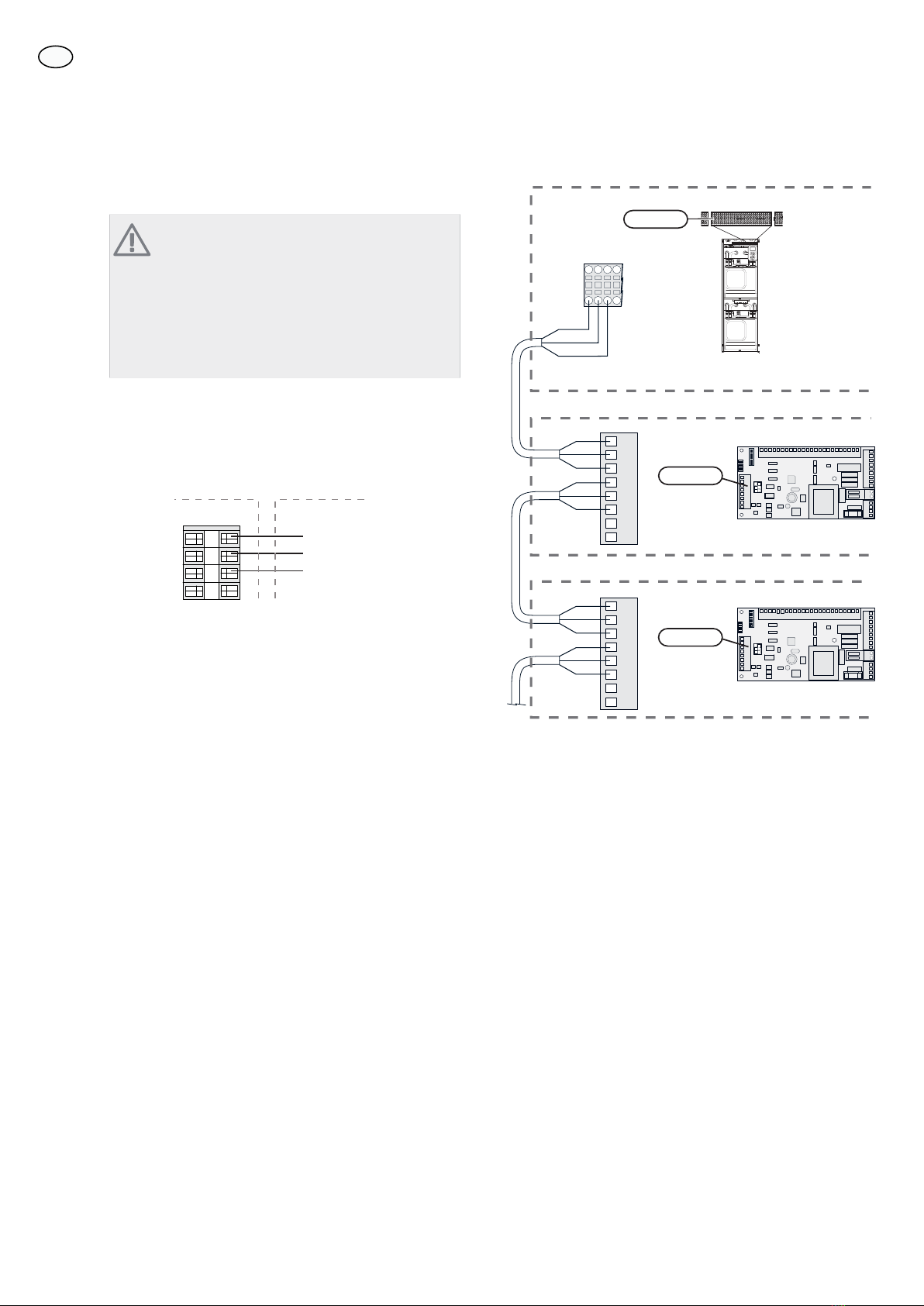
AB
A
B
႑Anslut köldbärare ut från värmepumpen
efter växelventil (QN12) via T-rör till port
A på shuntventilen (öppnar vid ökasignal).
႑Anslut returledningen från kylsystemet till
gemensam port AB på shuntventilen (alltid
öppen).
႑Anslut köldbärare in till värmepumpen från kollektorn
via T-rör till port B på shuntventilen (stänger vid
minskasignal).
Shuntventil, värmedump
Shuntventilen (QN36) placeras i klimatsystemet på fram-
ledningen från värmepumpen via T-rörsanslutningar enligt
principschema.
A
B
AB
႑Anslut framledningen till cirkulations-
pump, värmedump (GP20) och fläkt-
konvektorn till gemensam port AB på
shuntventilen (alltid öppen).
႑Anslut framledningen till klimatsyst-
met till port A på shuntventilen (öppnar vid ökasignal).
႑Anslut returledningen från fläktkonvektorn till fram-
ledningen till klimatsystemet via T-rör till port B på
shuntventilen (stänger vid minskasignal).
Växelventil, kyla/värme
Växelventilen (QN12) placeras i köldbärarsystemet på
framledningen från värmepumpen enligt principschema.
A
B
AB
႑Anslut framledningen till kylsystemet till port
A på växelventilen (öppen vid signal).
႑Anslut köldbärare ut från värmepumpen till
gemensam port AB på växelventilen (alltid
öppen).
႑Anslut köldbärare ut till kollektorn till port
B på växelventilen (normalt öppen, motor i viloläge).
Cirkulationspump, värmedump
Montera cirkulationspumpen (GP20) efter shuntventilen
för värmedump (QN36) på framledningen till fläktkonvek-
torn.
Volymkärl
Montera volymkärlet (CP21) för kyla på mellan växelventil
(QN12), shuntventil (QN18) och kylsystemet.
Temperaturgivare
႑Temperaturgivare (BT57) monteras på returen till
värmepumpen i kollektorn efter t-rörsanslutning från
kylsystemreturen via shuntventil (QN18).
႑Temperaturgivare (BT64) monteras på framledning
till kylsystemet vid t-rörsanslutning till volymkärl
(CP21).
႑Temperaturgivare (BT75) monteras på framledningen
till klimatsystemet efter värmedumpen.
Temperaturgivarna monteras med buntband tillsammans
med värmeledningspasta och aluminiumtejp. Därefter
skall de isoleras med medföljande isolertejp.
OBS!
Givar- och kommunikationskablar får ej förläggas
i närheten av starkströmsledning.
4
SE


 null")