Safety information
This manual describes installation and service proced-
ures for implementation by specialists.
This appliance can be used by children
aged from 8 years and above and per-
sons with reduced physical, sensory or
mental capabilities or lack of experience
and knowledge if they have been given
supervision or instruction concerning
use of the appliance in a safe way and
understand the hazards involved. Chil-
dren shall not play with the appliance.
Cleaning and user maintenance shall
not be made by children without super-
vision.
Rights to make any design or technical
modifications are reserved.
©NIBE 2015.
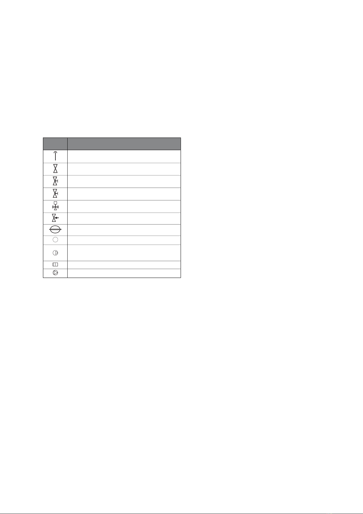
Symbols
NOTE
This symbol indicates danger to machine or
person.
Caution
This symbol indicates important information
about what you should observe when main-
taining your installation.
TIP
This symbol indicates tips on how to facilitate
using the product.
Marking
NIBE FLM is CE marked and fulfils IP21.
The CE marking means that NIBE ensures that the
product meets all regulations that are placed on it
based on relevant EU directives. The CE mark is obligat-
ory for most products sold in the EU, regardless where
they are made.
IP21 means that objects with a diameter larger than
or equivalent to 12.5 mm cannot penetrate and cause
damage and that the product is protected against
vertically falling drops of water.
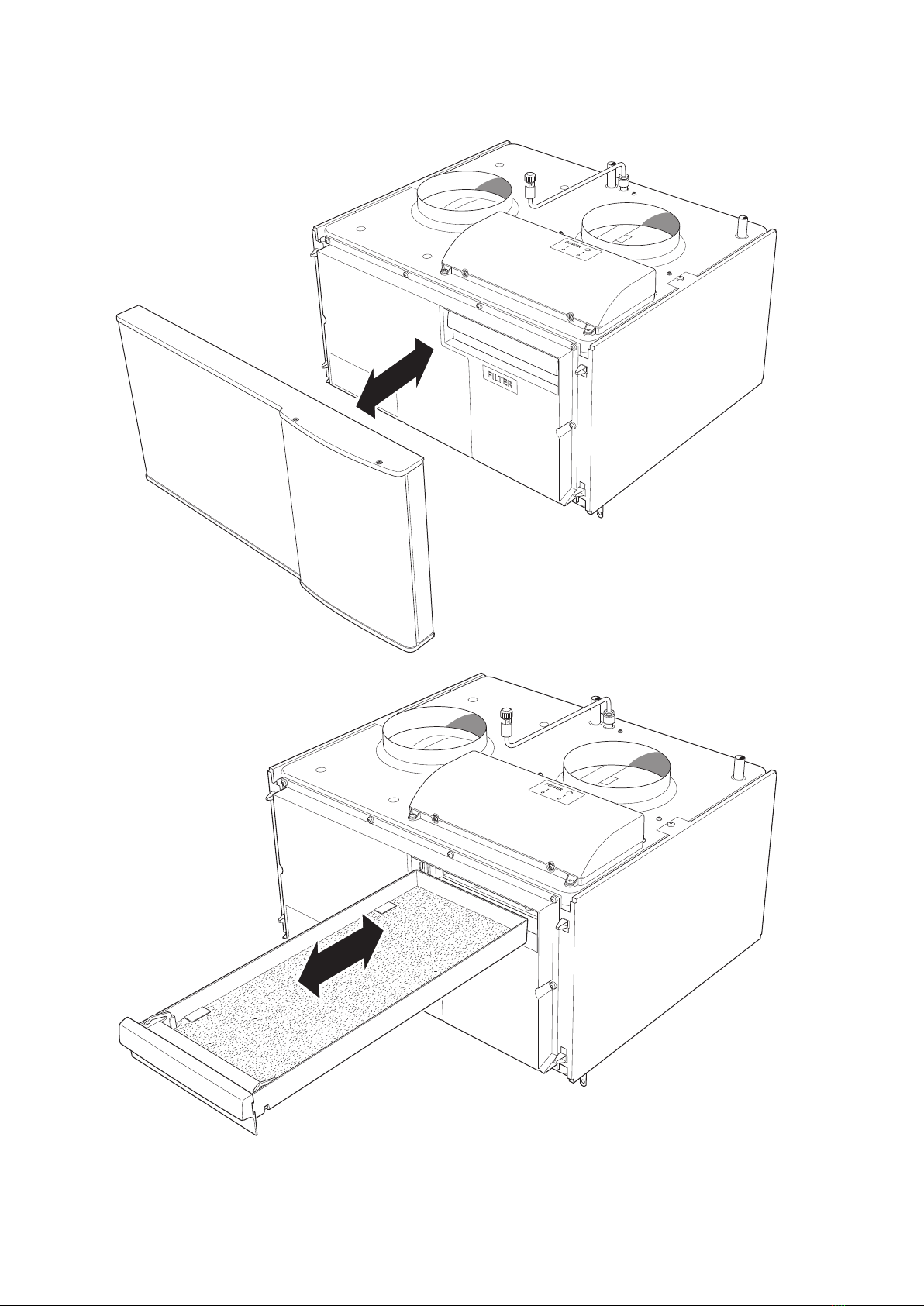
Serial number
The serial number can be found at the bottom left in-
side the front cover.
Caution
Always give the product's serial number (14
digits) when reporting a fault.
Country specific information
Installer manual
This installer manual must be left with the customer.
Passive cooling
For passive cooling, minimum software version 5539R5
is required.
NIBE FLMChapter 1 | Important information2
1 Important information


 null")