Nibe AMB 30 User manual

INSTALLATION AND MAINTENANCE INSTRUCTIONSMOS GB 1341-4
AMB 30
031533 AMB 30
Accessory, F1330
LEK

LEK

For the User
General
System description
Principle of operation 3
Outdoor air operation 3
Hybrid operation 3
The control unit
Maintenance routines
General 6
For the Installer
General points for the installation engineer
Inspection of the installation 7
Assembly 7
Control 7
Pipe connections
General 8
Pipe connection brine 8
Dimensioning of pressure expansion vessel 9
Positioning and dimensions 9
Connecting the hose to condensation water trough 10
Docking
General 11
Symbol key 11
Abbreviations 12
AMB 30 docked (outdoor air operation) to NIBE
F1330 13
AMB 30 docked (hybrid operation) to NIBE F1330 13
Several AMB 30 docked (outdoor air operation) to several
NIBE F1330 14
Several AMB 30 docked (hybrid operation) to several NIBE
F1330 15
Electrical connections
Cover removal and routing the power cable 16
General 17
Connection 17
Connecting several AMB 30 18
Connection of ambient sensor (BT28) 18
Connecting the circulation pump for defrosting (GP5) 18
Connecting the reversing valve for defrosting (QN20) 18
Connecting the temperature sensor for brine in to the heat
pump during hybrid operation (BT26) 19
Connecting the circulation pump for the rock/ground collect-
or during hybrid operation (GP2) 19
Connection of reversing valves during hybrid operation
(QN21 and QN22) 19
Connection of common alarm. 19
Connecting the control unit, BCU 30 (AA25) 20
Connection, compressor blocking in NIBE F1330 when de-
frosting 21
Connecting low pressure switch to NIBE F1330 (non-hybrid
system) 22
Commissioning and adjusting
Preparations 23
Filling and venting the brine system 23
Start-up and inspection, Outdoor air operation 23
Start-up and inspection, Hybrid operation 23
Readjusting, collector side 23
Adjustment, charge flow 23
Sensor placement
Temperature sensor data 24
Miscellaneous
Control
General 25
Menus 25
Alarm management 30
Electrical circuit diagram
Technical specifications
Component positions 34
Sound pressure levels 36
Dimensions and setting-out coordinates 37
Technical specifications 38
Enclosed kit 40
Accessories 40
Dealing with malfunctions
Checking the status 41
AMB 30 is not operational 41
Interference when defrosting 41
1AMB 30
Table of Contents

General
In order to get the greatest benefit from AMB 30 you should read through the "For the User" section in this Installation
and Maintenance Instruction.
AMB 30 is a heat absorbing air module that is an accessory for NIBE F1330. Outdoor air is used as a heat source.
AMB 30 is a Swedish-made quality product offering a long life span and reliable operation.
Serial number* (103), must always be stated in all correspondence with NIBE.
______________
Installation date
Type designation
AMB 30-____
Installation engineers
Settings
Enter deviations from default settings.Enter deviations from default settings.
Set-
ting
MenuSet-
ting
Menu
..........................................................................................................................
..........................................................................................................................
..........................................................................................................................
..........................................................................................................................
..........................................................................................................................
..........................................................................................................................
..........................................................................................................................
..........................................................................................................................
..........................................................................................................................
..........................................................................................................................
..........................................................................................................................
..........................................................................................................................
..........................................................................................................................
..........................................................................................................................
..........................................................................................................................
Datum__________________________ Sign___________________________
*See "Component positions" page 34 for location of the serial number.
This appliance can be used by children aged from 8 years and above and persons with reduced
physical, sensory or mental capabilities or lack of experience and knowledge if they have been
given supervision or instruction concerning use of the appliance in a safe way and understand
the hazards involved. Children shall not play with the appliance. Cleaning and user maintenance
shall not be made by children without supervision.
Rights to make any design or technical modifications are reserved.
©NIBE 2013.
AMB 302
For the User
General

System description
Principle of operation
AMB 30 is a heat absorbing air module that is an accessory
for NIBE F1330. AMB 30 is connected to F1330 only (out-
door air operation) or in combination with rock/ground
collector (hybrid operation) in order to supply the heat
pump with renewable energy. AMB 30 utilises the outdoor
air so there is no need for bore holes or coils in the ground.
AMB 30 is in principle an element that exchanges the air’s
energy with a liquid system using an axial fan and control
system. The fan has two speeds that either change auto-
matically at the selected ambient temperature or is
manually set to high/low speed.
The unit’s control system is connected to a control unit
(BCU 30) where all the settings and monitoring occurs.
This control unit is installed indoors. The control system
manages all functions such as fan operation, defrosting,
selection of operating mode, and stopping the compressor
during defrosting and at low ambient temperature.
The material has been chosen for a long service life and is
designed to withstand demanding outdoor conditions.
Outdoor air operation
During outdoor air operation AMB 30 only uses the out-
door air as a heat source and operation is permitted down
to an outdoor air temperature of approx -7 °C. Outgoing
brine from F1330 is connected directly to the air module.
When the ambient temperature is lower than the dimen-
sioned balance temperature (the lowest temperature
where the heat pump can manage all the heating) addi-
tional heat must be accessible to supplement the heat
pump.
M
Hybrid operation
In hybrid operation AMB 30 uses the outdoor air in com-
bination with ground /rock collector as the heat source.
Outgoing brine from the F1330 is connected directly to
the air module and on via a reversing valve to the
ground/rock collector.
Outdoor air operation only
When the ambient temperature is higher than 12 °C (se-
lectable) the control switches the reversing valves to oper-
ation with only AMB 30. Above this ambient temperature
the brine temperature is more effective from the AMB 30
than the ground/rock collector.
M
3AMB 30
For the User
System description

Hybrid operation
When the outdoor air temperature is between approx.0
and 12°C the controls switches the reversing valves to op-
eration with both AMB 30 and ground/rock collector (hy-
brid operation). At these temperatures the heat pump can
use both the ground/rock collector and AMB 30 to supply
the energy as long as the ambient temperature is suffi-
ciently much warmer than the brine temperature. This
operating mode increases the unit’s efficiency and uses
both the ground/rock collector and AMB 30 in the best
way.
M
Ground/rock collector operation only
When the ambient temperature falls the temperature
difference between outdoor air and the brine is reduced.
At a set min. difference the control switches to operation
with only ground/rock collector.
In this mode AMB 30 cannot contribute to increasing the
brine temperature. It is more efficient for the unit to use
just the ground/rock collector.
M
The brine, heating medium and domestic hot water side must be
fitted with the necessary safety equipment in accordance with the
applicable regulations.
AMB 304
For the User
System description

The control unit
This chapter runs through the control unit and its display
modes. The display mode is accessed by pressing [OK].
The display mode shows the temperatures that are read
off from the different temperature sensors that are con-
nected to AMB 30.
The [-] and [+] buttons are used to scroll through the dif-
ferent units (if several are connected).
In the example below the control unit shows that the brine
temperature in to the heat pump (BT26) is 5 °C and the
outdoor temperature (BT28) is 3 °C.
MR
OK
MR
OK
Temperatures
AMBno1
BT28
OK
Ground
5 °C/3 °C
Operationmode
BT21
BT27
BT26
3.0°C
13.0°C
3.8°C
5.0°C
5AMB 30
For the User
The control unit

Maintenance routines
General
AMB 30 is equipped with control and monitoring equip-
ment, however some exterior maintenance is still neces-
sary.
Make regular checks throughout the year that the inlet
grille is not clogged by leaves, snow or anything else. Check
through the cold part of the year to make sure that there
isn't a build up of ice or frost under AMB 30. The condens-
ation water trough is available for management and re-
moval of condensation. Strong wind combined with heavy
snowfall can block the intake and exhaust air grilles. Make
sure that there is no snow on the grilles.
If necessary the outer casing can be cleaned using a damp
cloth. Care must be exercised so that AMB 30 is not
scratched when cleaning. Avoid spraying water into the
grilles or the sides so that water penetrates into AMB 30
Prevent AMB 30 coming into contact with alkaline cleaning
agents.
!WARNING!
Rotating fan
LEK
Keep free of snow and/or ice.
LEK
Prevent ice and/or snow building up under AMB 30.
LEK
Prevent snow building up and covering the grille on AMB 30.
AMB 306
For the User
Maintenance routines

General points for the installation engineer
Inspection of the installation
Current regulations require the heating installation to be
inspected before it is commissioned. The inspection must
be carried out by a suitably qualified person and should
be documented. The above applies to closed heating sys-
tems.
If AMB 30 is replaced, the installation must be inspected
again.
For outdoor air systems (not hybrid systems) NIBE F1330
(serial number from 06510X10263YYY, where X is 0, 1, 2
or3 and YYY is a serial number) must be connected to a
prepared low pressure switch. Heat pumps manufactured
earlier do not have this extra low pressure switch and
cannot be used in an outdoor air system with AMB 30.
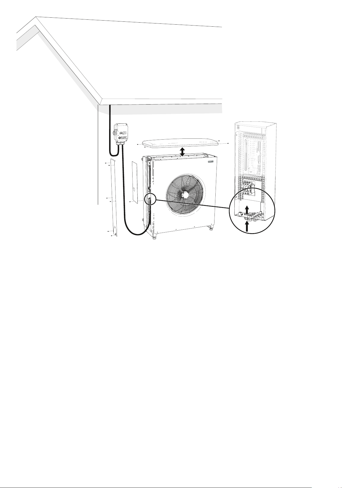
Assembly
AMB 30 should be installed outdoors on a firm and level
surface, preferably a concrete foundation with ground
stand or wall mounting. The AMB 30 should not be posi-
tioned next to sensitive walls, for example, next to a bed-
room. Also ensure that the placement does not inconveni-
ence the neighbours.
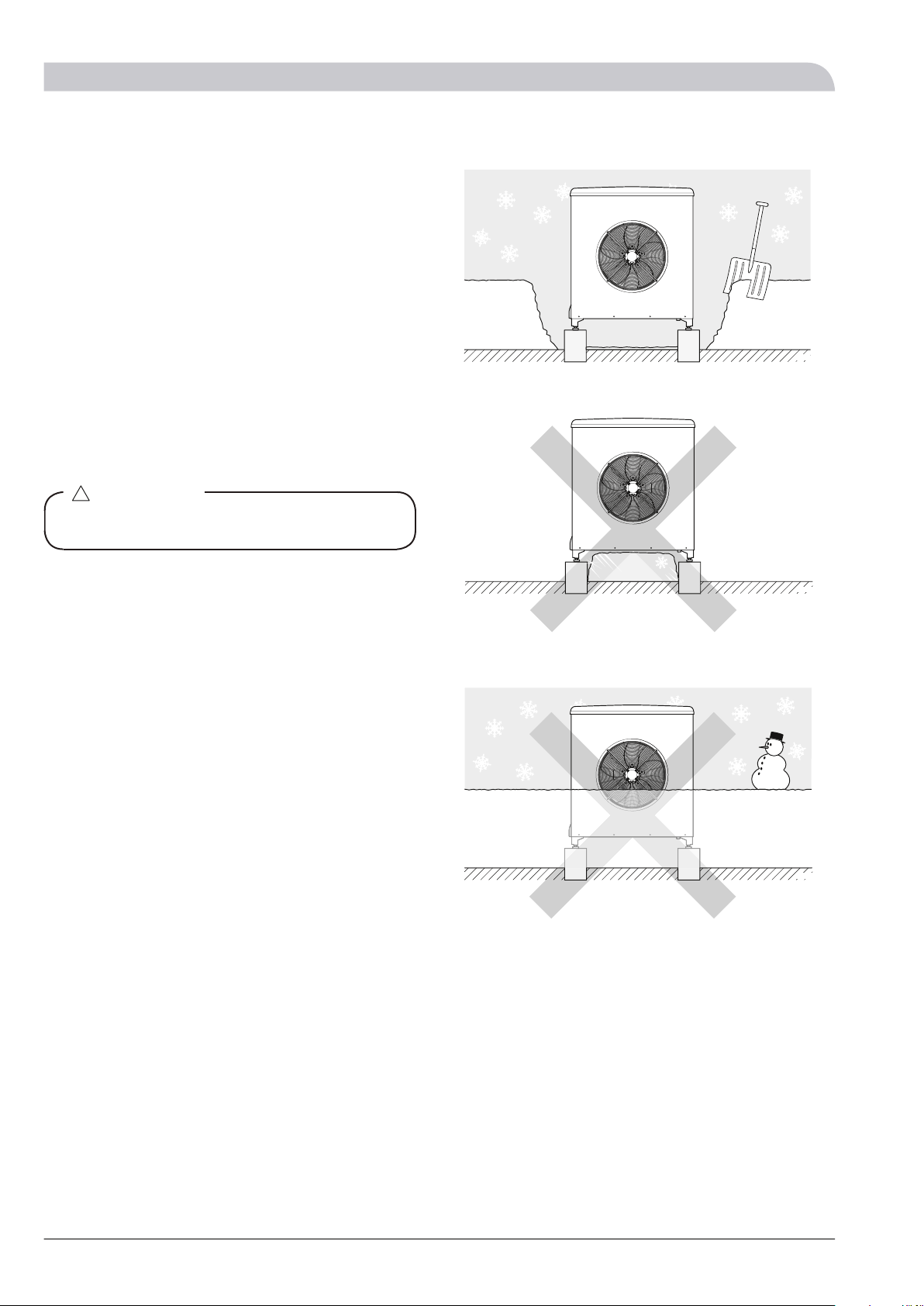
Large amounts of condensation water as well as melt
water from defrosting can be produced. Provide good
drainage at the installation area and make sure water
cannot run out onto paths or the like during periods that
ice can form. Ideally condensation water is led off to a
drain or similar.
The distance between AMB 30 and the house wall must
be at least 400 mm. Clearance in front of AMB 30 should
be at least one metre. AMB 30 must not be placed so
that recirculation of the outdoor air can occur. AMB 30
must not be placed in a windy location where it is ex-
posed to direct strong winds. This causes lower output
and impaired efficiency.
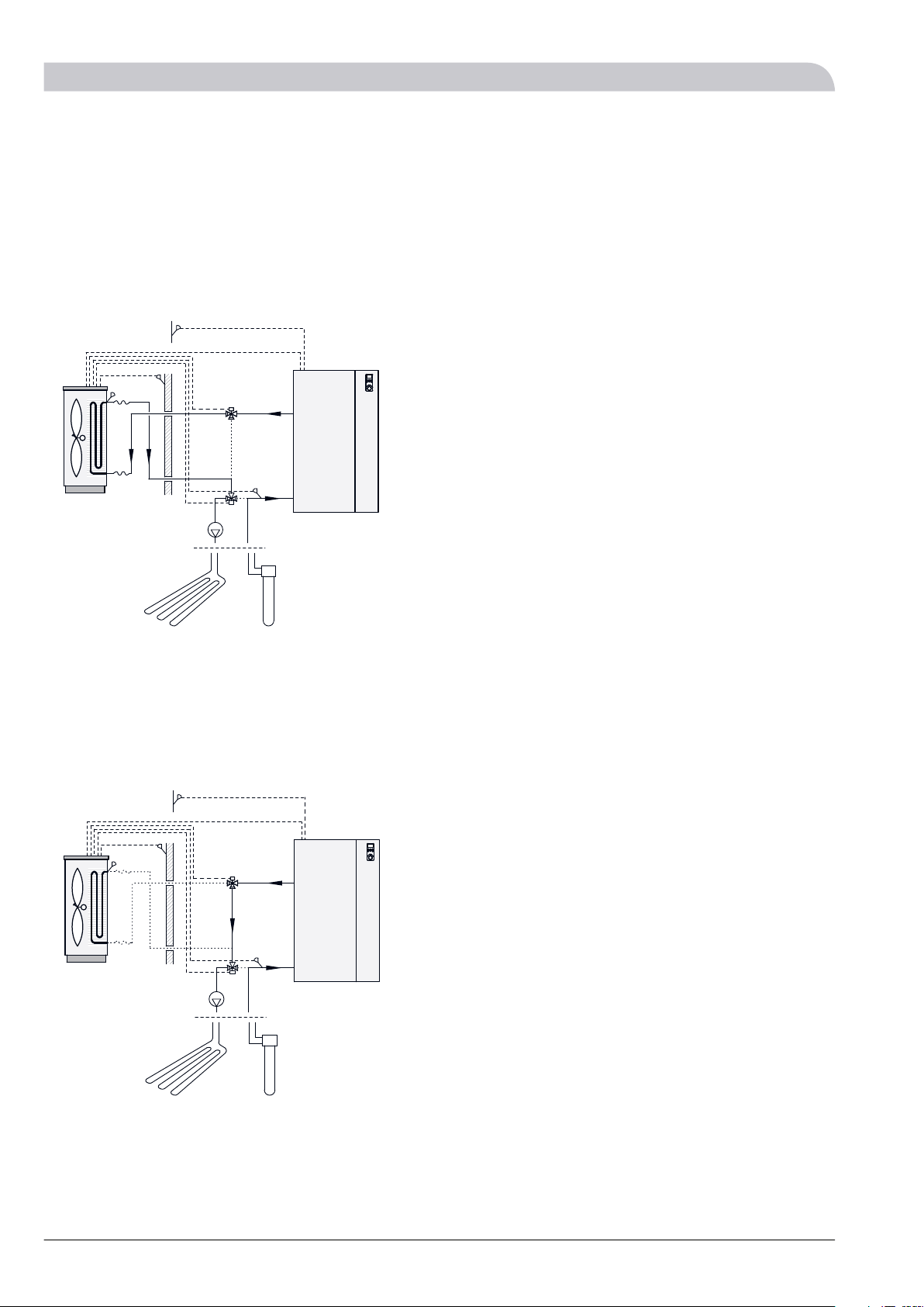
Control
AMB 30 is equipped with an internal electronic controller
that handles all functions necessary for operation.
Defrosting, stop at max/min temperature, circulation
pumps, reversing valves, blocking of the compressor in
NIBE F1330 as well as enabling the heater for the drip pan
are controlled accordingly.
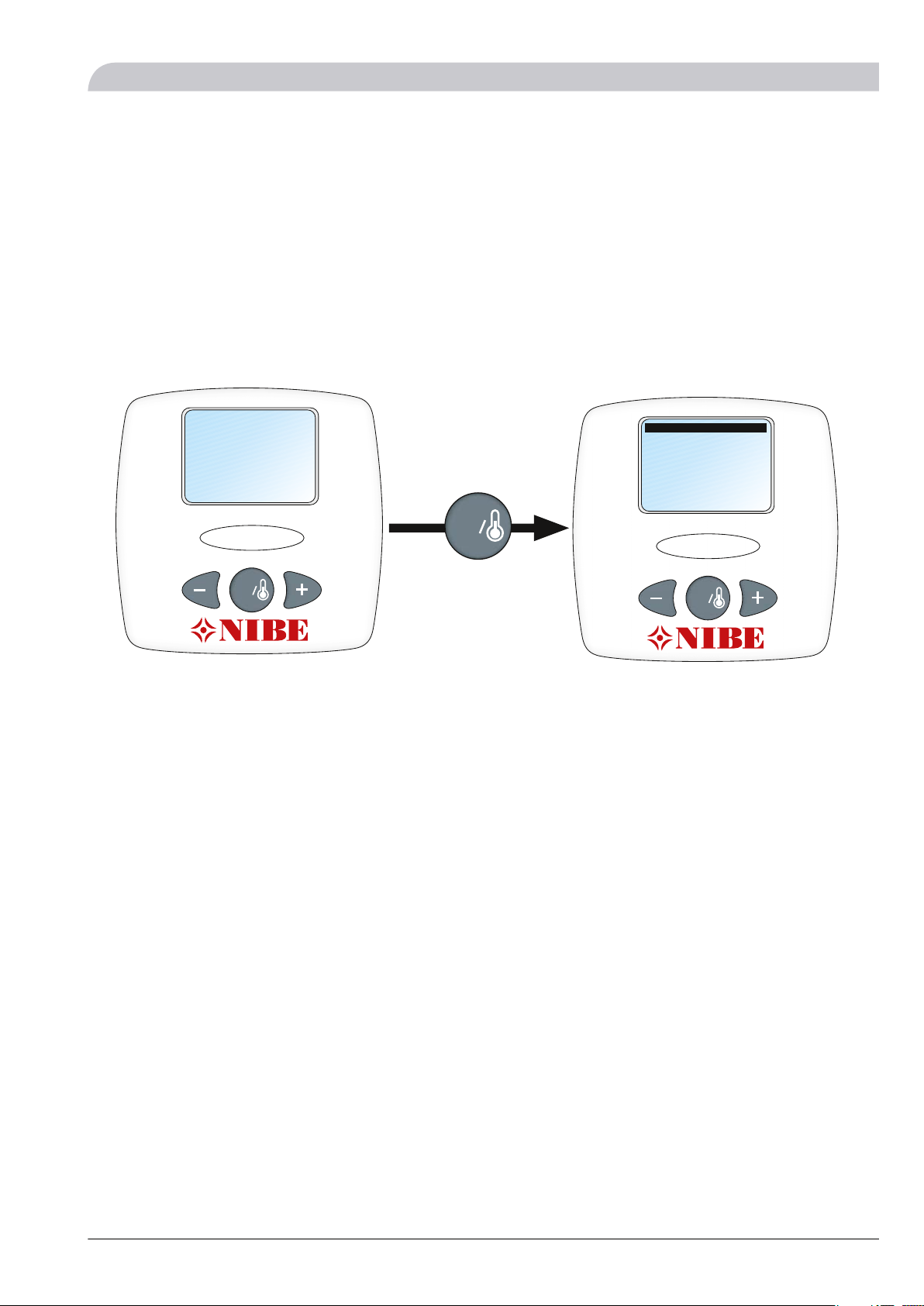
The integrated controller is set via the control unit (located
indoors) during installation and can be used during service.
400 mm
400 mm
3 m
Fritt utrymme
Fritt utrymme framför
Serviceutrymme
800 mm
Min. avstånd
vid användning
av flera AMB30
)UHH VSDFH
6HUYLFH DUHD
)UHH VSDFH LQ IURQW
0LQ GLVWDQFH ZKHQ XVLQJ VHYHUDO $0%
7AMB 30
For the Installer
General points for the installation engineer

Pipe connections
General
Pipe installation must be carried out in accordance with
current norms and directives.
Because AMB 30 is not equipped with shut off valves, drain
valve and vent valve these must be installed to facilitate
any future servicing.
NOTE
If AMB 30 is installed in an existing system any level
vessel on the brine side must be replaced with a
pressure expansion vessel.
NOTE
The pipe work must be flushed before AMB 30 is
connected, so that any contaminants do not damage
the components parts.
Pipe connection brine
AMB 30 can be connected to the brine system according
to one of the system solutions under the section "Docking"
or that can be downloaded from the website www.nibe.eu.
AMB 30 must be vented by the upper connection (XL7,
brine out) using the venting nipple (not supplied) installed
on the pipe.
The brine anti-freeze must be dimensioned to at least the
installation location's dimensioned outdoor temperature
(DUT).
On installation with only outdoor air operation, the brine
in the pipes must be ethylene glycol (40% volume percent).
Refer to the "Installation and Maintenance Instructions"
for installation with hybrid operation.
When several AMB 30 are installed in the same system
each AMB 30 must be equipped with control valves to
adjust the flow.
LEK
NOTE
All outdoor brine lines must be insulated against
condensation.
LEK
AMB 308
For the Installer
Pipe connections

Dimensioning of pressure expansion vessel
Hybrid operation (Ethanol 28% volume percent)
In hybrid operation (ethanol 28%) the pressure expansion
vessel must be dimensioned according to the following
diagram.
30
0
40
50
60
0
10
20
100 200 300 400 500 600 700 800 900 1000 1100 1200 1300 1400 1500
9ROXPH SUHVVXUH H[SDQVLRQ YHVVHO O
7RWDO YROXPH UHIULJHUDQW LQ V\VWHP O
Hybrid operation or outdoor air operation (Ethylene
glycol 40% volume percent)
In those cases where ethylene glycol (40%) is used on in-
stallation of hybrid operation or outdoor air operation the
pressure expansion vessel must be dimensioned according
to the following diagram.
0 200 400 600 800 1000 1200 1400 1600 1800 2000
0
10
20
30
40
50
60
70
80
90
100
9ROXPH SUHVVXUH H[SDQVLRQ YHVVHO O
7RWDO YROXPH UHIULJHUDQW LQ V\VWHP O
Positioning and dimensions
LEK
;/
;/
Min. recommen-
ded pipe dimen-
sion
Dimension (mm)Type
cu 42DN40(XL6) brine in
cu 42DN40(XL7) brine out
9AMB 30
For the Installer
Pipe connections

Connecting the hose to condensation water
trough
The condensation water collected in the trough should be
routed to an appropriate drain, it is recommended that
the shortest outdoor stretch possible is used. The condens-
ation water can (with reservations for local rules and reg-
ulations) be routed to a drain indoors. See basic circuit
diagram below. It is also possible to route the water to a
gutter or similar for example.
The whole length of the outdoor pipe must be heated by
the heating coil (not included in delivery, connected ex-
ternally) to prevent freezing.
Route the pipe downward from AMB 30.
Insulate the pipe (at least 19 mm of insulation) all the way
outside.
LEK
Fix the drainage hose to the connection under AMB 30
(recommended dimension 32 mm) with hose clamps.
NOTE
Hose with heating cable for draining the condensa-
tion water trough is not included.
NOTE
The electrical installation and wiring must be carried
out under the supervision of an authorised electrician.
AMB 3010
For the Installer
Pipe connections

Docking
General
AMB 30 can be installed in several different ways. The re-
quisite safety equipment must be installed in accordance
with current regulations for all docked options.
See www.nibe.eu for more docking options.
NOTE
These are outline diagrams. Actual installations must
be planned according to applicable standards.
See the appropriate “Installation and Maintenance
Instructions” for more information.
Outdoor air operation
Defrosting
When the ambient temperature falls below +5 -+6 °C the
air module needs to be defrosted. The intelligent controls
in AMB 30 ensure that defrosting is always optimised and
demand controlled.
At temperatures above approx +3 °C defrosting is passive,
that is the energy is retrieved from the outside air by the
fan in operation. At lower temperatures active defrosting
is required when the energy is retrieved from the house's
heating system via a heat exchanger.
Limiting the flow temperature
The flow temperature is limited linearly from -5 °C / 65 °C
to -15 °C / 50 °C.
Limiting the return temperature
The return temperature is limited linearly from -5 °C / 58 °C
till -15 °C / 44 °C.
Hybrid operation
Defrosting
At certain ambient temperatures defrosting of the air
module may be required even in hybrid operation, this
applies to operation at minus degrees in both outdoor air
and brine.
Change temperature
Change temperature in AMB 30 is the temperature when
the control system moves operating mode to only outdoor
air during hybrid operation.
Symbol key
MeaningSymbol
Venting valve
Shut-off valve
Non-return valve
Safety valve
Trim valve
Temperature sensor
Expansion vessel
Pressure gauge
P
Circulation pump
Shuttle valve
Particle filter
Auxiliary relay
Compressor
Heat exchanger
11AMB 30
For the Installer
Docking

Abbreviations
ExplanationDesignation
Control unitAA25
Temp.sensor, HTF, collector inBT26
Temp.sensor, OutdoorBT28
NIBE F1330 MasterEB100
Temp.sensor, OutdoorBT1
Temp.sensor, Hot waterBT6
Temp. sensor, External flow lineBT25
Pressure expansion vessel, HTFCM3
Safety valve, HTFFL3
Circulation pump, HTFGP2
Particle filterHQ1 - HQ3
NIBE F1330 SlaveEB101
Circulation pump, HTFGP2
Particle filterHQ1
Defrosting kitEP40
Exchanger, defrostingEP17
Circulation pump, defrostingGP5
Reversing valve, defrostingQN20
AMB 30 1 (Master)EP100
Temp.sensor, VentBT21
Temp.sensor, HTF, collector outBT27
AMB 30 2 (Slave)EP101
AMB 30 3 (Slave)EP102
AMB 30 4 (Slave)EP103
Miscel-
laneous
Manometer, HTFBP6
Pressure expansion vessel closedCM4
Accumulator tankCP1
Electric boilerEB1
Hot water heaterEB2
Collector, HTFEP12
Safety valve, HMFL2
Safety valve, Heat pumpFL10 - FL11
Circulation pump, HTF, externalGP2
Circulation pump, HM, ExternalGP10
Auxiliary relayKA1
Venting valve, HTFQM21
Shut off valve, HM-rQM32
Shut off valve, HTF-rQM34
Shut-off valveQM40 - QM41
QM50 - QM55
Venting valveQM60 - QM64
Reversing valve, Heating/hot waterQN10
Reversing valve, Hybrid operationQN21
Reversing valve, Outdoor airQN22
Reversing valve, defrosting in the event of
several AMB 30, connected as QN20 in the
wiring diagram
QN51 - QN53
ExplanationDesignation
Valve, AdjustingRN10 - RN13
RN15 - RN16
RN20 - RN21
RN50 - RN53
Non-return valveRM5
RM10 - RM19
AMB 3012
For the Installer
Docking

AMB 30 docked (outdoor air operation) to NIBE F1330
-RN10
-RN11
-HQ1
-EB100-HQ3
-FL10
-QM32
-QM34
-QM64
-HQ2
-QN10
A
B
-EB100
-RN15
M
-BT21
-EP100
-QM60
-QM50
-AA25
P
-BP6
-QM21
-EB100-CM3
-EB100-FL3
-EB100
-EB100
-KA1
-EB100
-EP40 -RM10
-RM11
-EB100-BT1
-BT6
-CP1
-CM4
-FL2
-QM40
-QM41 -RN16
-EB1
-EB100-BT25
-RM5
-GP10
-EP40-GP5
-EP40-EP17
-QN20
-AA25-BT26
-AA25-BT28
-BT27
-EB2
1
2
3
AMB 30 docked (hybrid operation) to NIBE F1330
-RN10
-RN11
-HQ1
-EB100-HQ3
-FL10
-QM32
-QM64
-HQ2
-GP2
M
-BT21
-EP100
-RN15
-QM60
-QM50
A
B
-EB100
-EB100
-QM34
P
-BP6
-QM21
-EB100-CM3
-FL3
-AA25
-EB100
-KA1
-EB100
-EB100
-EP40
-RM10
-RM11
-EB100-BT1
-QN10
-AA25
-BT6
-CP1
-EB2
-CM4
-FL2
-QM40
-QM41 -RN16
-EB1
-EB100-BT25
-RM5
-GP10
-EP12
-EP40-EP17
-QN20
-BT26
-QN21
-AA25-BT28
-QN22
-EP40-GP5
-BT27 1
2
3
1
2
3
1
2
3
13AMB 30
For the Installer
Docking

Several AMB 30 docked (outdoor air operation) to several NIBE F1330
-QN10
-RN12
-RN13
-HQ1
-EB100-HQ3
-FL10-FL11
-RN10
-RN11
-HQ1
-QM55
-QM34
-QM64
-HQ2
A
B
-EB101
A
B
-EB100
-AA25
-RN20 -RN21
-RN15
-AA25-BT28
-RN51
-QM51
-QM61
M
-BT21
-EP100
M
-BT21
-EP101
M
-BT21
-EP102
M
-BT21
-EP103
-QM60 -RN50
-QM50
-RN52
-QM52
-QM62
-RN53
-QM53
-QM63 -GP2 -GP2
-EB101 -EB100
-EB101
-EB100
-QM32
-EB100
-KA1
-EB100-BT1
-EB100
P
-BP6
-QM21
-EB100-CM3
-FL3
-EB100
-QM54
-EP40
-RM10
-RM12
-RM14 -RM15
-RM11
-RM13
-BT27
-BT27
-BT27
-BT27
-RM18
-RM19
-RM17
-RM16
-BT6
-CP1
-CM4
-FL2
-QM40
-QM41 -RN16
-EB1
-EB100-BT25
-RM5
-GP10
-EP40-GP5
-EP40-EP17
-AA25-BT26
-QN53
-QN52
-QN51
-QN20
-EB2
1
2
3
1
2
3
1
2
3
1
2
3
AMB 3014
For the Installer
Docking

Several AMB 30 docked (hybrid operation) to several NIBE F1330
-QN10
-RN12
-RN13
-HQ1
-EB100-HQ3
-FL10-FL11
-RN10
-RN11
-HQ1
-QM55
-QM34
-QM64
-HQ2
A
B
-EB101
A
B
-EB100
-AA25
-RN20 -RN21
-GP2
-RN15
-AA25-BT28
-RN51
-QM51
-QM61
M
-BT21
-EP100
M
-BT21
-EP101
M
-BT21
-EP102
M
-BT21
-EP103
-QM60 -RN50
-QM50
-RN52
-QM52
-QM62
-RN53
-QM53
-QM63 -GP2 -GP2
-EB101 -EB100
-EB101
-EB100
-QM32
-EB100
-KA1
-EB100-BT1
P
-BP6
-QM21
-EB100-CM3
-FL3
-EB100
-EB100
-QM54
-EP40
-RM10
-RM12
-RM14
-RM18
-RM19
-RM17
-RM16
-RM15
-RM11
-RM13
-BT27
-BT27
-BT27
-BT27 -BT6
-CP1
-CM4
-FL2
-QM40
-QM41 -RN16
-EB1
-EB100-BT25
-RM5
-GP10
-EP40-GP5
-EP40-EP17
-AA25-BT26
-QN53
-QN52
-QN51
-QN20
-QN22
-QN21
-EP12
-EB2
1
2
3
1
2
3
1
2
3
1
2
3
1
2
3
1
2
3
15AMB 30
For the Installer
Docking

Electrical connections
NOTE
Electrical installation and service must be carried out
under the supervision of a qualified electrician. Elec-
trical installation and wiring must be carried out in
accordance with the stipulations in force.
NOTE
The live external control must be taken into consider-
ation when connecting.
NOTE
The heat pump must not be powered when installing
AMB 30.
Cover removal and routing the power cable
LEK
AMB 3016
For the Installer
Electrical connections

General
The cables for heavy current and the signal cables should
be routed from the side at the folded part of the side
panel on the left-hand side of AMB 30. Power supply is
routed through the cable grommet UB1, power supply for
the circulation pumps and reversing valves through UB2
toUB4, communication cables through UB5 to UB7 and
signal cables through the remaining cable grommets.
Connection
႑Connection of AMB 30 may not occur without the ap-
proval of the electricity supplier and must be supervised
by an authorised electrician.
႑If a miniature circuit breaker is used it should have motor
characteristic “C”. For MCB size see "Technical Specifica-
tions".
႑AMB 30 does not include an omnipolar circuit breaker
on the incoming power supply. The supply cable from
AMB 30 must be connected to a circuit-breaker with at
least a 3 mm breaking gap. If the building is equipped
with an earth-fault breaker, AMB 30 should be equipped
with a separate one. Incoming supply must be 400 V
3NAC 50Hz via distribution boards with fuses.
႑If an insulation test is to be carried out in the building,
disconnect the heat pump and AMB 30.
႑Connect cables in spring terminals as illustrated.
LEK
ca: 1 mm
ca: 3 mm
Connecting the incoming electrical supply
135
246
L1 L2 L3 N PE
X1FA1
LEK
FA1
UB1
UB2-4
UB5-7
AA6-COM1
AA6-X8
AA6-F1
AA6-X6
AA6-X7
AA6-SF2
AA6-COM2
X1
AA6-X4
AA6-X3
AA6
17AMB 30
For the Installer
Electrical connections

Connecting several AMB 30
Up to 9 x AMB 30 can be connected to the same installa-
tion.
Each unit can be set on the switch AA6-SF2 which states
which unit is which in the installation (the main unit = 1
etc.).
AA6-SF2
54321
offoffoffoffonAMB 30 1
offoffoffonoffAMB 30 2
offoffonoffoffAMB 30 3
offonoffoffoffAMB 30 4
onoffoffoffoffAMB 30 5
onoffoffoffonAMB 30 6
onoffoffonoffAMB 30 7
onoffonoffoffAMB 30 8
ononoffoffoffAMB 30 9
The units are connected in series where the main unit is
connected from COM2 on the relay card (AA6) to COM1
on the relay card in the slave unit, which can be repeated
to the next slave unit etc. (see image). Suitable cable type
is for example LiYY 3x0.50 or similar.
1
GND
COM1
COM2
A
B
GND
A
B
1
GND
COM1
COM2
A
B
GND
A
B
1
GND
COM1
COM2
A
B
GND
A
B
GND
A
B
GND
A
B
GND
A
B
GND
A
B
GND
A
B
AMB 30 1
AMB 30 2
AMB 30 3
AA6-COM1 AA6-COM2
AA6-COM1 AA6-COM2
AA6-COM1 AA6-COM2
Connection of ambient sensor (BT28)
The ambient sensor (BT28) is located in a shaded location
near the air intake for the AMB 30.
Connect the sensor to terminal block X8:1 and X8:2 on
the relay card (AA6) as illustrated. Use a 2 core cable of at
least 0.5 mm² cable area.
If a conduit is used it must be sealed to prevent condensa-
tion in the sensor capsule.
1
2
3
X8
ExternalAMB 30
BT28AA6-X8
NOTE
BT28 is only connected to the main unit (on installa-
tion of several AMB 30).
Connecting the circulation pump for defrosting
(GP5)
The circulation pump for defrosting (GP5) is connected to
terminal block X3:4 (L), X3:5 (N) and X3:6 (PE) on the relay
card (AA6) as illustrated.
Max connection output on this connection is250W. Use
the accessory HR10 if more output is required.
X3
1
2
3
4
5
6
L
N
PE
AA6-X3
GP5
External AMB 30
NOTE
GP5 is only connected to the main unit (on installation
of several AMB 30).
Connecting the reversing valve for defrosting
(QN20)
The reversing valve for defrosting (QN20) is connected to
terminal block X4:1 to X4:4 on the relay card (AA6) as illus-
trated.
X4
1
2
3
4
5
AA6-X4
QN20
External AMB 30
AMB 3018
For the Installer
Electrical connections
Other manuals for AMB 30
1
Table of contents
Other Nibe Air Conditioner manuals
Popular Air Conditioner manuals by other brands

Carrier
Carrier RAV180 installation instructions

Hokkaido
Hokkaido HKEI-HCNI 263 XR Service manual

Delphi
Delphi OM 611 DELA installation instructions

Mitsubishi Electric
Mitsubishi Electric MFZ-KA25VA Service manual

Airwell
Airwell YCV Series Service manual

Panasonic
Panasonic CS-LZ9ZKA operating instructions