Nibe BA-SVM 10-200 Series User manual

21-01-2019
25-08-2020
631043-1 EN
INSTALLATION AND USER MANUAL
Indoor module for air to water split systems
NIBE BA-SVM 10-200


3NIBE BA-SVM 10-200
Table of Contents
1 Important information _______________ 4
Safety information _______________________ 4
2 Delivery and handling___________ 6
Available models ________________________ 6
Compatibility ___________________________ 6
Transport ______________________________ 6
Assembly______________________________ 6
Installation ____________________________ 7
Removing the covers______________________ 7
Supplied components _____________________ 7
3 Design of the indoor unit _______ 8
BA-SVM 10-200 _________________________ 8
4 Pipe connections ______________ 10
General information ______________________10
System diagram _________________________11
Dimensions and pipe connections ____________15
Other information________________________15
Docking the indoor unit____________________16
Installation alternative ____________________20
Hot water circulation _____________________22
5 Outdoor unit _____________________ 23
Delivery and handling _____________________23
Installation ____________________________23
Lift from the street to the set-up location __________ 23
Lift from the pallet to final positioning _________24
Scrapping _____________________________24
Condensation water drain __________________24
Recommended alternative for leading o
condensation water ______________________24
Dimensions ____________________________26
Installation location ______________________28
Sound power levels ______________________28
6 Electrical connections _________29
General information ______________________29
Connections____________________________30
Settings_______________________________32
7 Commissioning and adjusting_33
Preparations ___________________________33
Filling and venting _______________________33
Circulation pump ________________________34
Commissioning__________________________34
Start Guide ____________________________34
8 Control- Introduction __________36
Display _______________________________36
Menu system___________________________37
9 Control _________________________40
Menu 1 – INDOOR CLIMATE ________________40
Menu 2 – HOT WATER ____________________41
Menu 3 – INFO__________________________41
Menu 4 – MY SYSTEM____________________42
Menu 5 – SERVICE _______________________43
Start guide_____________________________44
User settings ___________________________46
Service submenus _______________________55
Cooling operation settings__________________61
10 Service ________________________62
Service operations _______________________62
11 Disturbances in comfort _______ 66
Troubleshooting _________________________66
Additional heat only ______________________67
12 Accessories___________________68
Available accessories _____________________68
Connecting the KVR accessory_______________69
13 Technical data _________________70
Dimensions and pipe connections_______________ 70
Technical data __________________________71
Performance ___________________________72
Energy eciency label ____________________73
Energy eciency specifications of the package ___ 73
Energy label____________________________74
Electrical wiring diagrams__________________77

4NIBE BA-SVM 10-200
1 Important information
Safety information
Serial number
Symbols
Marking
BA-SVM 10-200 is CE marked and
has an IP21 protection rating.
The CE mark confirms that NIBE
has ensured that the product
conforms to all applicable regula-
tions specified by the relevant EU
directives. The CE mark is man-
datory for most products sold in
the EU, regardless of where they
are made.
IP21 means that objects with a
diameter greater than or equal to
12.5 mm cannot penetrate and
cause damage and that the prod-
uct is protected against vertically
falling drops of water.
This appliance can be used by
children aged 8 years and above
and persons with reduced phys-
ical, sensory or mental capacity
or lack of experience and knowl-
edge, if they will be supervised
or have received instruction con-
cerning safe use of the appliance,
and if they understand the dan-
ger involved in its use. Children
must not play with the appliance.
Cleaning and basic maintenance
of the appliance must not be car-
ried out by children unsupervised.
The rights to make structural
changes are reserved.
©NIBE 2020
This manual contains installation
and service procedures for imple-
mentation by specialists.
The serial number is located at
the bottom of the identification
plate, on the top cover BA-SVM
10-200 and consists of 14 digits.
CAUTION
This symbol indicates danger
to the appliance or person.
NOTE
This symbol indicates im-
portant information to note
while operating or main-
taining the appliance.
TIP
This symbol indicates tips
that will make it easier to
operate the product. Serial number
BA-SVM
(PF3)
Section 1 | Important information

5NIBE BA-SVM 10-200 Section 1 | Important information
Waste disposal
Leave the disposal of the
packaging to the installer
who installed the product
or to a special waste dis-
posal facility. Improper disposal of the product by
the user may result in administrative
penalties in accordance with the ap-
plicable legislation.
Do not dispose of used products
with normal household waste. It
must be transported to a special
Description Notes Signature Date
Heating medium
Flushing the system
System vented
Expansion vessel
Particulate filter
Safety valve
Shut-off valves
Pressure in the climate system
Connected according to outline diagram
Hot water
Shut-off valves
Mixing valve
Safety valve
Electric power supply
Connecting communication
Circuit fuses
Fuses, indoor unit
Mains fuse
Outdoor temperature sensor
Room sensor
Current sensor
Safety circuit breaker
Residual-current device
Setting the thermostat to emer-
gency mode
Miscellaneous
Docked to
Inspection of the installation
The climate system must be inspected before commissioning. The inspection must be carried out by a suitably
qualified person. In addition, fill in the page for the installation data in the User Manual.
Checklist
waste disposal facility or to a ven-
dor who provides this type of ser-
vice.

6NIBE BA-SVM 10-200
2 Delivery and handling
Transport
Available models
Compatibility
Assembly
The BA-SVM 10-200 indoor unit should be transport-
ed and stored vertically in a dry place. However,
BA-SVM 10-200 may be carefully laid on its back
when being moved into a building.
BA-SVM 10-200 units include the following separate
models:
• BA-SVM 10-200/6 E - unit dedicated for use with
AMS 10-6, enamelled tank equipped with a tita-
nium anode,
• BA-SVM 10-200/12 E - unit dedicated for use
with AMS 10-8 and AMS 10-12, enamelled tank
equipped with a titanium anode,
• BA-SVM 10-200/6 E EM - unit dedicated for use
with AMS 10-6, enamelled tank equipped with a
titanium anode, and energy meter,
• BA-SVM 10-200/12 E EM - unit dedicated for use
with AMS 10-8 and AMS 10-12, enamelled tank
equipped with a titanium anode and energy me-
ter,
• BA-SVM 10-200/6 R - unit dedicated for use with
AMS 10-6, stainless steel tank,
• BA-SVM 10-200/12 R - unit dedicated for use with
AMS 10-8 and AMS 10-12, stainless steel tank.
• BA-SVM 10-200 must be placed on a solid, water-
proof surface that will support the weight of the
filled indoor unit. Use the adjustable feet of the
indoor unit for horizontal and stable positioning of
the appliance.
• Since BA-SVM 10-200 has condensation water
drainage, the set-up location of the indoor unit
should be equipped with a floor drain leading to
the sewage system.
20-40 mm
Wrench size 13
The BA-SVM 10-200 indoor unit can be used with
Split type outdoor units. The compatible NIBE SPLIT
heat pumps are:
Symbol Application
AMS 10-6 BA-SVM 10-200/6
AMS 10-8 BA-SVM 10-200/12
AMS 10-12
You can find more information on NIBE SPLIT heat
pumps at www.nibe.eu and in the relevant instruc-
tions for installation and use.
In the Accessories section, you can check the list of
accessories that can be used with BA-SVM 10-200.
Section 2 | Delivery and handling

7NIBE BA-SVM 10-200
Supplied components
Leave a free space of 800 mm in front of the indoor
unit. All servicing of BA-SVM 10-200 can be carried
out from the front.
1. Remove the screws from the lower edge of the front
cover.
2. Tilt back the cover at the lower edge paying
special attention not to damage the connecting
cables, then remove the front cover by lifting it
upwards.
3. Disconnect the cable connecting the front cover
to the unit.
Installation location
CAUTION
If connecting an additional heat source, leave sufficient
space behind the appliance for problem-free comple-
tion of the connections and future maintenance.
25-30 mm
800 mm
Removing the covers
3
Safety group with safe-
ty valve (3 bar), pressure
gauge and automatic air
vent (1 pc.)
Temperature sensor
Outdoor and indoor
(2 pcs)
Connection p.27
Current sensor (3 pcs) 230V connection
jumper (1 pc.)
CAUTION
The rated opening pressure of the safety valve is 3
bar.
Section 2 | Delivery and handling
• Safety group (1 pc.)
• Outdoor / indoor temperature sensor (2 pcs)
• Current sensor (3 pcs.)
• 230V connection jumper (1 pc.)
• Built-in energy meter (BA-SVM 10-200 E EM only)
• Instalation and user manual
LEK
LEK
LEK

8NIBE BA-SVM 10-200Section 3 |
3 Design of the indoor unit
BA-SVM10-200
Design of the indoor unit
XL11 XL10 XL4 XL13 XL14
XL3
GP12
AA27
AA8
AA2:X4
AA2:X15
AA2
K2
BT64
XL2
XL1
EP2
QN12
BT12
BF1
CM1 BP4
EB1 BT15
BT63 BT3
BT6
BT7
X10
X0
BT30
FD1
X1
EB1
AA23
FA1
K1A-K3A
FA2
AA3
SF1
X2
AA7
EB2
BT71
XL5 BT25
QN10

9NIBE BA-SVM 10-200
Pipe connections
XL1 Connection, heating medium, supply
XL2 Connection, heating medium, return
XL3 Connection, cold water
XL4 Connection, hot water
XL5 Connection, hot water circulation
XL10 Connection, cooling operation
XL11 Connection, safety assembly,
pressure gauge
XL13 Connection, liquid refrigerant
XL14 Connection, gas refrigerant
HVAC components
CM1 Expansion vessel, closed
QN10 Reversing valve, hot water/climate system
QN12 Reversing valve, heating system/cooling
system
GP12 Circulation pump
EP2 Heat exchanger
Sensors
BP4 Pressure sensor, high pressure
BT3 Temp. sensor, heating medium return
BT6 Temp. sensor, hot water charging
BT7 Temp. sensor, hot water heater top
BT12 Temp. sensor, condenser out
BT15 Temp. sensor, liquid line
BT25 Temp. sensor, heating medium supply
BT63 Temp. sensor, supply heating medium be-
hind immersion heater
BT64 Temp. sensor, cooling operation system
supply
BT71 Temp. sensor, heating medium return
Electrical components
X0 Terminal block- 400V~
X1 Terminal block- 230V~
X2 Terminal block- 230V~
X10 Terminal block- 230V~
AA2:X4 Terminal block- low voltage
AA2: X15 Terminal block- low voltage
K1A-K3A Contactor for immersion heater
K2 Alarm relay
BT30 Standby mode thermostat
AA2 Main board
AA3 Sensor board
AA23 Communication board
AA7 Relay board
AA8 Titanium anode board
(Does not apply to BA-SVM 10-200 R
AA27 Relay board
FD1 Thermal circuit breaker
FA1 Miniature circuit breaker (protecting the
indoor unit)
FA2 Miniature circuit breaker (protecting the
outdoor unit)
EB1 Electric additional heat
Miscellaneous
BF1 Energy meter
(BA-SVM 10-200 E EM only)
SF1 Controller switch
EB2 Hot water tank
Section 3 | Design of the indoor unit

10 NIBE BA-SVM 10-200Section 4 |
4 Pipe connections
General information
Pipe installation must be carried out in accordance with
the current standards and directives.
The pipe dimensions should not be less than the rec-
ommended pipe diameter according to the table below.
However, in order to achieve the recommended flow,
each installation must be dimensioned individually.
The system can be used with a low- and medium-tem-
perature climate system. The recommended tem-
perature of the heating medium at the dimensioned
outdoor temperature DOT must not exceed 55°C on
the supply and 45°C on the return circulation from the
climate system. BA-SVM 10-200 can reach up to 65°C
when using the electric additional heat or another peak
heat source.
An overflow pipe must be routed from the safety valve
to a suitable drain. The entire length of the overflow
pipe must be inclined towards the floor drain to pre-
vent water pockets and must also be frost-proof. In or-
der to reach maximum system efficiency, we recom-
mend installing BA-SVM 10-200 as close as possible to
the outdoor heat pump.
The BA-SVM 10-200 unit is not equipped with a shut-
off valve for the climate system. In order to facilitate
future servicing, the shut-off valves should be in-
stalled on the outside of the indoor unit.
The BA-SVM 10-200 unit can be docked to the central
heating, cooling operation and hot water systems. It
is absolutely necessary to install the supplied safety
assembly on connection XL11.
Air/water
heat pump
Minimum flow
during defrost-
ing
(100% pump
capacity [l/s])
Minimum
recom-
mended
pipe dimen-
sion (DN)
Minimum
recommend-
ed pipe
dimension
(mm)
BA-SVM 10-200/6
+ AMS 10-6 0,19 20 22
BA-SVM 10-200/12
+ AMS 10-8 0,19 20 22
BA-SVM 10-200/12
+ AMS 10-12 0,29 20 22
CAUTION
All high points in the climate system must be equipped
with air vents.
CAUTION
The pipelines need to be flushed out before the indoor
unit is connected so that any debris cannot damage
component parts.
CAUTION
Until the system’s heating/cooling circuit has been
filled with heating medium, the switch (SF1) in the
controller must not be set to “I” or „ ”. If you do not
comply with the above instructions, many compo-
nents of the BA-SVM 10-200 unit may be damaged.
Minimum system flow
The installation must be dimensioned at least to the
extent required to manage the minimum defrosting
flow at 100% circulation pump operation, see table.
CAUTION
An incorrectly dimensioned climate system can result
in damage to the appliance and lead to malfunctions.
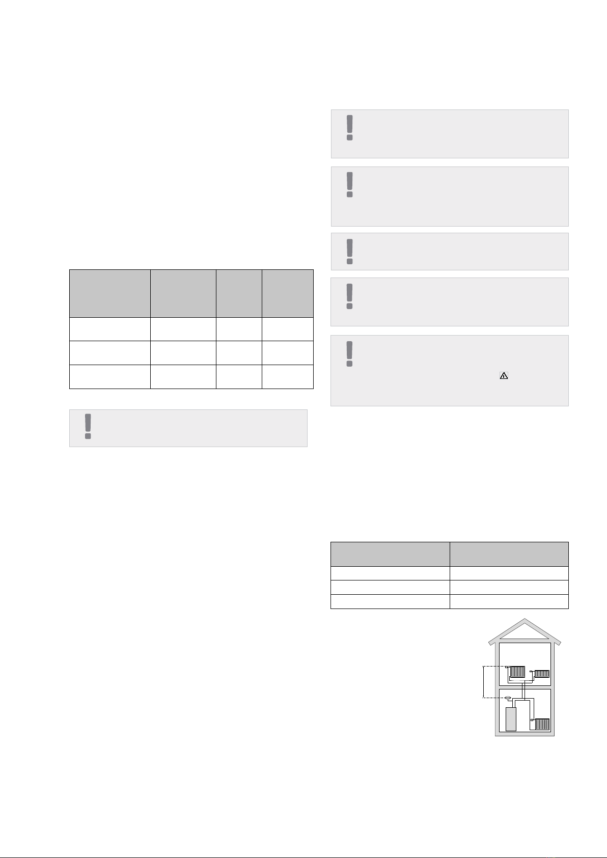
BA-SVM 10-200 is equipped
with an expansion vessel with
a 10l capacity.The pressure set-
ting in the level vessel should
be set according to the maxi-
mum height (H) between the
vessel and the highest-posi-
tioned radiator, see drawing.
An initial pressure of 0.5 bar
The expansion vessel’s volume must be at least 5% of
the system’s total volume. BA-SVM 10-200 appliances
have been equipped with an expansion vessel with a
10l volume. If the capacity of the built-in expansion
vessel is insufficient, an additional expansion vessel
meeting the above requirements should be added to
the installation.
Table with examples:
Total volume [l]
(indoor unit and climate system)
Volume [l],
expansion vessel
500 10+15
750 10+25
1000 10+40
Expansion vessel
H
(5 mvp) means a maximum permissible height dif-
ference of 5 m. The maximum volume of the system
without a boiler is 220 l at the above initial pressure.
Pipe connections
CAUTION
In the installation before the BA-SVM 10-200, a par-
ticulate filter should be used, dedicated for heating
installations. The filter will protect the unit against pol-
lution.
CAUTION
Ensure that incoming water is clean. When using a pri-
vate well, it maybe necessary to supplement with an
extra water filter.

11NIBE BA-SVM 10-200
The BA-SVM 10-200 indoor unit is equipped with a
storage tank with a hot water coil, expansion ves-
sel, safety group, electric additional heat, reversing
valves, plate heat exchanger, energy meter, electron-
ic circulation pump and controller. Combined together
with the NIBE SPLIT (AMS 10) outdoor air heat pump
unit, it forms a complete climate system.
The AMS 10 outdoor unit supplies thermal energy for
heating domestic water, powering the climate sys-
tem, heating swimming pools and cooling operation,
using free energy contained in the air outside, work-
ing efficiently in the low temperature range, as low
as -20°C.
The connection of the outdoor unit and the indoor unit
BA-SVM 10-200, with a system of pipes filled with re-
frigerant, protects the connection against freezing in
the event of interruptions in the electric power supply
to appliances. The system’s operations are controlled
using an advanced controller.
The control mechanism of BA-SVM 10-200 allows for
two cooling operation systems to be used:
• 2-pipe cooling system,
• 4-pipe cooling system.
System diagram
NOTE
BA-SVM is equipped with all temperature sensors as
standard. In some system layouts, the sensors must be
transferred to other parts of the system. For location of
the sensors, see the relevant point on docking the sys-
tem.
NOTE
In the event that the water volume of the central heating
system is increased using a buffer vessel, you will need
to check the system volume and possibly increase the
volume of the existing expansion vessel.
Section 4 | Pipe connections
If the standard initial pressure in the expansion vessel
is too low, this can be increased by filling it via the
installed valve. The expansion vessel’s standard initial
pressure must be entered in the checklist on page 5.
Any change in the initial pressure affects the ability of
the expansion vessel to handle the expansion of the
heating medium.
CAUTION
In order to obtain the minimum undisturbed flow in
the climate system, use the appropriate hydraulic solu-
tions (e.g. relief valve, low loss header, parallel buff-
er and/or open heating loops). Remember to always
maintain the minimum required flow in the system -
see the subsection “Minimum system flow”.
Buffer vessel
Minimum climate system volumes
NOTE
It is recommended to have an expansion vessel in the
hot water system. However, it is required to install a
safety valve with the required opening pressure.
The heat pump installation requires an appropriate
volume of heating medium (approx. 10l/kW heat
pump power) and a minimum, undisturbed flow.
In case of an insufficient amount of heating medium
in the installation, an additional buffer vessel must be
used, which will ensure adequate system volume,
see subsection “Minimum climate system volumes”.
An insufficient flow in the central heating system will
cause malfunction of the heat pump installation and
could lead to serious damage of the product.
AMS 10 6 8 12
Minimum climate system volume during
heating/cooling 50l 80l 100l

12 NIBE BA-SVM 10-200
Shut-off valve
Non-return valve
Shunt valve
Safety valve
Temperature sensor
Expansion vessel
Pressure gauge
Automatic air vent
Basic diagram
Circulation pump
Electric heating
Cooling system filter
Compressor
Plate heat exchanger
Cooling operation
Heating system
(radiators)
Central heating system
(under floor heating sys-
tems)
Domestic hot water
Relief valve
Additional heat source
Buffer vessel
Fan coil
-BT64
A dotted line indicates
that you need to transfer
the temperature sensor
Section 4 | Pipe connections
XL10
XL1
XL2
-EB101
-BT1
BA-SVM 10-200
-GP11
P
XL18XL19
HS1 -BP4
-BT15
-BT3
-GP12 -BT25
-QN12 -BT63
-BT71
-QN10
-BT7
-BT6
P
EQ-BT25/BT64

13NIBE BA-SVM 10-200
The operating principle of the 2-pipe system is to
use the same installation for cooling operation as
for heating (Diagram of 2-pipe cooling operation). In
the 2-pipe system, the control mechanism operates
The operating principle of the 4-pipe system is to use
separate heating and cooling circuits. In the 4-pipe sys-
tem, a cooling tank is required. The BT64 sensor should
be placed in the buffer vessel or on the cooling flow
Diagram of 2-pipe cooling operation
Diagram of 4-pipe cooling operation
all components of the system i.e. GP10, expansion
modules (additional heating/cooling circuits) etc. Se-
lection of the 2-pipe system can be found in the SER-
VICE section, menu 5.2.4.
pipeline. BT64 is connected at the AUX inputs. Selec-
tion of the 4-pipe system can be found in the SERVICE
section, menu 5.2.4.
Section 4 | Pipe connections
XL10
XL1
XL2
-EB101
-BT1
BA-SVM 10-200
-GP11
P
XL18XL19
HS1 -BP4
-BT15
-BT3
-GP12 -BT25
-QN12 -BT63
-BT71
-QN10
-BT7
-BT6
P
-BT2
-BT3
-QN11
-GP20
AA25
EQ-BT25/BT64
XL10
XL1
XL2
-EB101
-BT1
-BT64
BA-SVM 10-200
-GP13
P
XL18XL19
HS1 -BP4
-BT15
-BT3
-GP12 -BT25
-QN12 -BT63
-BT71
-QN10
-BT7
-BT6
P
EQ-BT25/BT64
-GP11

14 NIBE BA-SVM 10-200
• It is recommended that you install the
BA-SVM 10-200 unit in a room which is equipped
with a floor drain and protected against freezing.
• The ground should be of a sufficient load capaci-
ty, preferably concrete.
• The BA-SVM 10-200 unit must be positioned with
its back against a building wall.The device should
not be placed against the walls of rooms in use
where noise could be a problem.
• The appliance can be levelled using the adjusta-
ble feet.
• Route pipes so they are not adjacent to the wall
of a bedroom or living room where noise could
be a problem.
• Ensure that there is approx. 800 mm free space
in front of and 500 mm above the appliance to
facilitate any future servicing.
1. Dock the BA-SVM 10-200 unit to the central heat-
ing system as well as the cold and hot water
pipelines.
2. Install refrigerant pipes.
3. Connect the current sensors, outdoor tempera-
ture sensor, the lines between BA-SVM 10-200
and AMS 10, as well as the communication and
power supply.
4. Connect the electric power supply (230V or 400V)
to the BA-SVM 10-200 unit.
5. Proceed according to the commissioning instruc-
tions in the section Commissioning and adjust-
ing.
Recommended order of assembly
XL10
XL1
XL2
-EB101
-BT1
BA-SVM 10-200
-GP11
P
XL18XL19
HS1 -BP4
-BT15
-BT3
-GP12 -BT25
-QN12 -BT63
-BT71
-QN10
-BT7
-BT6
P
EQ-BT25/BT64
Diagram showing connection of an additional heat source
NOTE
The maximum recommended power of the additional
heat source cannot exceed 15kW.
Section 4 | Pipe connections

15NIBE BA-SVM 10-200
Dimensions and pipe connections
Pipe connections
XL1 Connection, heating medium supply Ø22 mm
XL2 Connection, heating medium return Ø22 mm
XL3 Connection, cold water Ø22 mm
XL4 Connection, hot water Ø22 mm
XL5 Conduit to hot water circulation connection
Ø15 mm
XL10 Connection, cooling operation Ø22 mm
XL11 Connection, safety assembly
Ø22 mm, pressure gauge
XL13 Liquid refrigerant
Connection 1/4”(BA-SVM 10-200/6)
Connection 3/8” (BA-SVM 10-200/12)
XL14 Gas refrigerant
Connection 1/2” (BA-SVM 10-200/6)
Connection 5/8” (BA-SVM 10-200/12)
XL 18 Connection, return to add. heat source
Ø22 mm
XL 19 Connection, supply from add. heat source
Ø22 mm
Other information
PF3 BA-SVM serial number plate
PF4 Software serial number plate
20-40
1590 115
XL11
XL10
XL4 XL5 XL3 XL2 XL1
XL14
XL13
PF3
PF4
600.5
610.5
300
156
93.5 92.5 87 63 55
65
155
44
152
XL18
XL19
103mm
XL11 XL10 XL4 XL13 XL14 XL3
XL2
XL1
Section 4 | Pipe connections

16 NIBE BA-SVM 10-200
Docking the indoor unit
Docking the climate system
An external heat source with a maximum power of
15kW, e.g. a gas or oil boiler, can be connected to the
back of the BA-SVM 10-200 unit by removing the plate
blocking access to the connection ports (see drawing
below). Diagram- see p.11.
The BA-SVM 10-200 unit has a condensate hose to drain
the condensation water from the drip tray located under
the hot water tank. The pipe drains all of the condensa-
tion water away from the appliance, minimizing the risk
of damage. This pipe can be extended if needed.
The refrigerant pipes must be installed between the
AMS 10 outdoor unit and the BA-SVM 10-200 indoor unit.
Installation must be carried out in accordance with the
current standards and directives.
Condensate
hose
Supply from
external heat
source
(XL 19)
Return to
external heat
source
(XL 18)
Limitations
• Maximum pipe length on either side, AMS 10-6,
AMS 10-8 and AMS 10-12 (L): 30 m.
• Maximum height difference (H): 7 m.
The pipe connections of the climate system are made
from the top of the appliance.
• All required safety devices and shut-off valves
must be fitted as close to the BA-SVM 10-200
unit as possible.
• Vent valves must be installed where necessary.
• The safety valve with the pressure gauge and
air vent on the central heating circuit, as well as
the safety valve on the hot water system must
be fitted to the appropriate connections XL 11
and XL 3. To prevent air pockets from forming,
the overflow pipe must be inclined in its entire
length from the safety valve and must also be
frost proof.
• When connecting to a system with thermostatic
valves on all radiators/underfloor heating pipes,
to ensure the proper flow and the proper heat-
ing medium volume, install a buffer vessel and
possibly a relief valve. See subsection “Minimum
system flow”.
CAUTION
The term “climate system” which is used in this in-
stallation and user manual signifies heating and cool-
ing operation systems that are supplied with heat or
cold using heating or cooling medium from the BA-
SVM 10-200 unit, for heating or cooling purposes.
Connection of external heat source
Removing condensate
Connecting the refrigerant pipe
(not included)
L
H
L
H
HK 200S
HK 200S
AMS 10
AMS 10
NOTE
It is absolutely necessary for the appropriate safety
valve to be fitted directly on the cold water supply pipe
to the HW tank, to protect the tank against an exces-
sive pressure increase.
NOTE
The outdoor unit, filled with refrigerant at the factory, al-
lows for the use of refrigerant pipes (size L) between the
outdoor unit and the indoor unit measured with a pipe
length of L = 15m. The maximum permissible length of
the refrigerant pipes can be 30m, however this requires
topping up the system with refrigerant.
BA-SVM 10-200
BA-SVM 10-200
Section 4 | Pipe connections

17NIBE BA-SVM 10-200
Refrigerant connection pipeline
specification
BA-SVM 10-200/12 Gas pipe (Ø ext.) Liquid line (Ø ext.)
Pipe dimensions Ø15,88 mm (5/8”) Ø9,52 mm (3/8”)
Connection Connection – (5/8") Connection – (3/8”)
Material Copper quality SS-EN 12735-1 or
C1220T, JIS H3300
Minimum wall
thickness 1,0 mm 0,8 mm
External diameter,
copper pipe
(mm)
B, using the tool
R410A (mm)
B, using the
conventional tool
(mm)
Ø 9,52
0,0~0,5
0,7~1,3
Ø 15,88
Ø 6,35 1,0~1,5
Ø 12,7
External diameter,
copper pipe
(mm)
Tightening
torque
(Nm)
Tightening
angle (°)
Recommended
tool length
(mm)
Ø6,35 14~18 45~60 100
Ø 9,52 34~42 30~45 200
Ø12,7 49~61 30~45 250
Ø 15,88 68~82 15~20 300
Pipe connection
• Carry out the pipe installation when the service
valves (QM35, QM36) are closed.
AMS 10-6 / AMS 10-8
• Remove the side panel from AMS 10 during in-
stallation to facilitate access.
Flare connections
Expansion:
Ejection:
AMS 10-12
• Remove the “punch-out” part from the external
panel on the AMS 10 unit, where the pipes are
to be routed. The drawing below shows the pipe
outlets to choose from.
• Take care to ensure no water or pollutants enter the
refrigerant connection pipe. Pollutants in the pipes
risks damage to the heat pump.
• Bend the pipes with the maximum bending radi-
A
B
Vacuum
pump
Manometer
Zawór serwisowy,
ciecz
Zawór serwisowy,
gaz
Wyjście pomiarowe
Manometr
Pompa
próżniowa
A
B
Vacuum
pump
Manometer
Zawór serwisowy,
ciecz
Zawór serwisowy,
gaz
Wyjście pomiarowe
Manometr
Pompa
próżniowa
CAUTION
Gas shielding must be used when soldering.
External diameter,
copper pipe A (mm)
Ø 6,35 9,1
Ø 9,52 13,2
Ø 12,7 16,6
Ø 15,88 19,7
BA-SVM 10-200/12
BA-SVM 10-200/6
us (at least R100~R150). Do not bend the pipes
repeatedly. Use a bending machine.
• Make and connect the flare-connection and tighten
with the appropriate torque using a torque wrench.
Use the appropriate tightening angle, if a torque
wrench is not available.
BA-SVM 10-200/6 Gas pipe (Ø ext.) Liquid line (Ø ext.)
Pipe dimensions Ø12,7 mm (1/2”) Ø6,35 mm (1/4”)
Connection Connection – (1/2") Connection – (1/4”)
Material Copper quality SS-EN 12735-1 or
C1220T, JIS H3300
Minimum wall
thickness 1,0 mm 0,8 mm
Section 4 | Pipe connections
Front
Elements to be removed

18 NIBE BA-SVM 10-200
Pressure test and leak test
Vacuum pump
Insulating refrigerant pipes
Filling the system with refrigerant
A
B
Vacuum
pump
Manometer
Zawór serwisowy,
ciecz
Zawór serwisowy,
gaz
Wyjście pomiarowe
Manometr
Pompa
próżniowa
Both BA-SVM 10-200 and AMS 10 are factory tested
for pressure and leakage, but the refrigeration pipe
connections between appliances should be checked
for leakage after installation. When connecting the pipes, carrying out pressure
tests and leak tests, and creating the vacuum, re-
member to keep the service valves (QM35, QM36)
closed. In order to fill the pipes of BA-SVM 10-200
with refrigerant, they must be reopened.
Connections:
Principle:
• Refrigerant pipes (both liquid and gas) must be
insulated for the purpose of thermal insulation
and in order to avoid condensation.
• Use insulation that can withstand at least 120°C.
Use a vacuum pump to remove all air. Apply suction
for at least one hour and end pressure after evacua-
tion must be 1mbar (100 Pa, 0.75 Torr or 750 micron)
absolute pressure. If the system is still damp or leak-
ing, the vacuum will decrease after the draining has
finished.
CAUTION
The pipe connection between the indoor unit and the
outdoor unit must be leak tested. Then create a vac-
uum for the completed pipeline after finishing instal-
lation, in accordance with the applicable regulations.
Only nitrogen must be used for compression and dry-
ing of the completed pipeline.
TIP
To achieve a better end result and speed up creation of
the vacuum, please follow the below points:
• The pipelines should have the correct diameter
and length.
• Drain the system to 4 mbar and fill it with dry
nitrogen to atmospheric pressure.
AMS 10 is delivered complete with the refrigerant
required for the installation of refrigerant pipes with
lengths of up to 15 m on either side.
If the length of the refrigerant pipes exceeds 15 m,
extra refrigerant must be added in the amount of
0.02kg/m for BA-SVM 10-200/6 or 0.06 kg/m for BA-
SVM 10-200/12.
Wires for connecting indoor
and outdoor units Exterior tape
Gas piping
Insulation
Liquid piping
Okablowanie
Rura z cieczą
Taśma
Rura gazowa
Izolacja
Przyłącza:
Band (accessory) Pipe cover (accessory)
Zworka Zabezpieczenie rury
Wires for connecting indoor
and outdoor units Exterior tape
Gas piping
Insulation
Liquid piping
Okablowanie
Rura z cieczą
Taśma
Rura gazowa
Izolacja
Przyłącza:
Band (accessory) Pipe cover (accessory)
Zworka Zabezpieczenie rury
NOTE
All connections and work related to the refrigeration
system must be carried out by a person with the prop-
er authorisations and certificates.
NOTE
The maximum permissible length of the refrigerant pipes
can be 30m, however this requires topping up the sys-
tem with refrigerant after a length of 15m is exceeded.
Metering output
Service valve,
liquid
Service valve,
gas
Pressure
gauge
Vacuum
pump
Jumper Pipe protection
Wiring
Tape
Gas pipe
Insulation
Liquid line
Section 4 | Pipe connections

19NIBE BA-SVM 10-200
Connections
General information
NIBE SPLIT can be connected in several different
ways. For more information about connections, go to
the website www.nibe.eu.
AMS 10-6 AMS 10-8 AMS 10-12
Maximum pressure, climate system 0,3 MPa (3 Bar)
Highest recommended flow/return temperature at dimensioned
outdoor temperature. 55/45 °C
Max. temperature in the unit BA-SVM 10-200 +65 °C
Maximum hot water temperature +65 °C
Minimum temperature ext. operation of the unit -20 °C
Minimum temperature ext. cooling operation +10 °C
Max. supply temperature, compressor +58 °C
Min. cooling supply temperature +7 °C
Max. cooling supply temperature +25 °C
Minimum volume, climate system during heating/cooling* 50 l 80 l 100 l
Max. flow, climate system 0,29 l/s 0,38 l/s 0,57 l/s
Min. flow, climate system 0,09 l/s 0,12 l/s 0,15 l/s
Min. flow, cooling system 0,11 l/s 0,16 l/s 0,20 l/s
* Refers to volume associated with undisturbed flow
Section 4 | Pipe connections

20 NIBE BA-SVM 10-200
Docking the indoor unit
Docking during use without heat pump
Connecting cold and hot water
The BA-SVM 10-200 unit is not equipped with a shut-off
valve for the central heating system, hot water system
or electric additional heat; these must be installed on
the outside of the indoor unit to facilitate any future ser-
vicing.
It is not necessary to change the configuration of the
hydraulic connections for the indoor unit to work in-
dependently without the outdoor unit.
The hot water tank should be connected to a water
supply system with water pressure of min. 1 bar,
max. 10 bar. If the pressure at the cold water inlet to
the tank is higher than the permissible level, use a
pressure reducer. During heating of the water in the
tank, the pressure increases, which is why each tank
must be equipped with the appropriate safety valve,
installed on the cold water supply, which will protect
the tank against an excessive increase in pressure.
If using hot water circulation, see subsection “Hot
water circulation”.
Installation alternative
P
P
P
-BT6
P
P
P
CAUTION
It is forbidden to install any constrictors (e.g. reduc-
ers, particle filter, etc.) and shut-off valves between
the storage tank and the safety valve. Only fitting a
tee with a draining valve and a tee with an expansion
vessel is permitted.
CAUTION
It is absolutely necessary to install a properly selected
safety valve on the cold water supply pipe.
CAUTION
Do not use the appliance if the safety valve is blocked.
Section 4 | Pipe connections
Other manuals for BA-SVM 10-200 Series
1
This manual suits for next models
6
Table of contents
Other Nibe Air Conditioner manuals