Röranslutning
Allmänt
För att undvika kondensbildning måste rörledningar
och övriga kalla ytor isoleras med diffusionstätt mate-
rial. Vid stort kylbehov krävs fläktkonvektor med
droppskål och avloppsanslutning.
Köldbärarkretsen skall förses med tryckexpansionskärl.
Eventuellt befintligt nivåkärl byts ut.
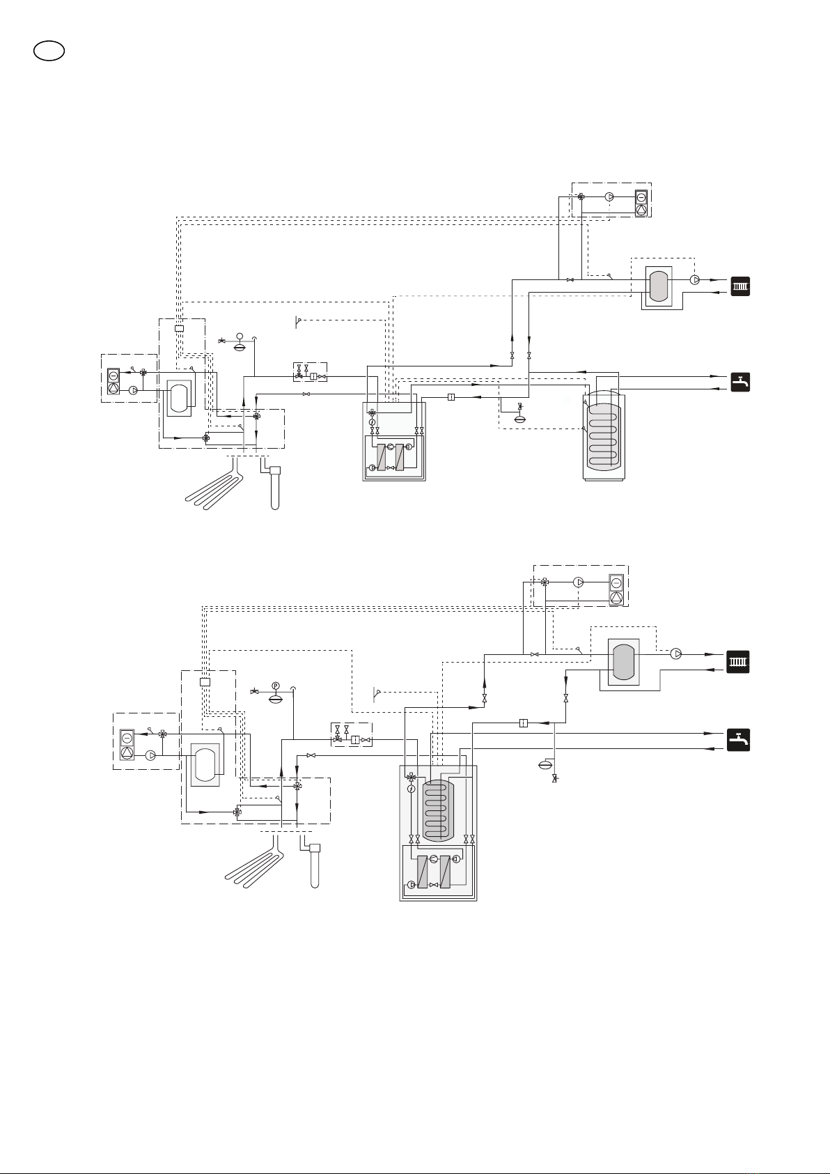
Backventil
Montera en backventil (RM22) mellan två T-rörsanslut-
ningarna till shuntventilen för värmedump (se prin-
cipschema).
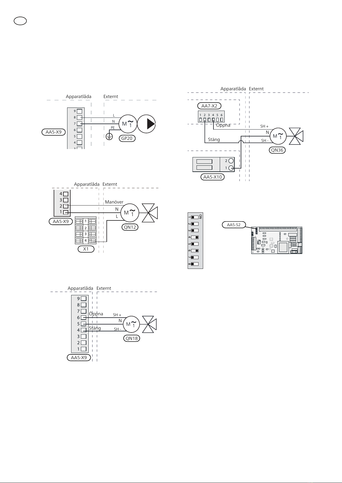
Shuntventil, kyldump
Shuntventilen (QN18) placeras i köldbärarsystemet via
T-rörsanslutningar enligt principschema.
■Anslut köldbärare ut från värmepumpen
efter växelventil (QN12) via T-rör till port
A på shuntventilen (öppnar vid ökasignal).
■Anslut returledningen från kylsystemet
till gemensam port AB på shuntventilen
(alltid öppen).
■Anslut köldbärare in till värmepumpen
från kollektorn via T-rör till port B på shuntventilen
(stänger vid minskasignal).
Shuntventil, värmedump
Shuntventilen (QN36) placeras i klimatsystemet på
framledningen från värmepumpen via T-rörsanslutning-
ar enligt principschema.
■Anslut framledningen till cirkulations-
pump, värmedump (GP20) och fläkt-
konvektorn till gemensam port AB på
shuntventilen (alltid öppen).
■Anslut framledningen till klimatsyst-
met till port A på shuntventilen (öppnar vid ökasig-
nal).
■Anslut returledningen från fläktkonvektorn till
framledningen till klimatsystemet via T-rör till port B
på shuntventilen (stänger vid minskasignal).
Växelventil, kyla/värme
Växelventilen (QN12) placeras i köldbärarsystemet på
framledningen från värmepumpen enligt principsche-
ma.
■Anslut framledningen till kylsystemet till
port A på växelventilen (öppen vid signal).
■Anslut köldbärare ut från värmepumpen
till gemensam port AB på växelventilen
(alltid öppen).
■Anslut köldbärare ut till kollektorn till port
B på växelventilen (normalt öppen, motor
i viloläge).
Cirkulationspump, värmedump
Montera cirkulationspumpen (GP20) efter shuntventi-
len för värmedump (QN36) på framledningen till
fläktkonvektorn.
Volymkärl
Montera volymkärlet (CP21) för kyla på mellan växel-
ventil (QN12), shuntventil (QN18) och kylsystemet.
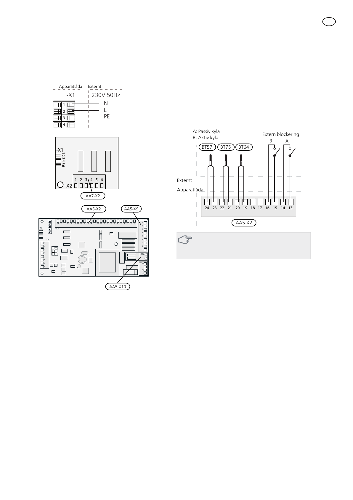
Temperaturgivare
■Temperaturgivare (BT57) monteras på returen till
värmepumpen i kollektorn efter t-rörsanslutning från
kylsystemreturen via shuntventil (QN18).
■Temperaturgivare (BT64) monteras på framledning
till kylsystemet vid t-rörsanslutning till volymkärl
(CP21).
■Temperaturgivare (BT75) monteras på framledningen
till klimatsystemet efter värmedumpen.
Temperaturgivarna monteras med buntband tillsam-
mans med värmeledningspasta och aluminiumtejp.
Därefter skall de isoleras med medföljande isolertejp.
OBS!
Givar- och kommunikationskablar får ej förläg-
gas i närheten av starkströmsledning.
4


 null")