Safety information
This manual describes installation and service proced-
ures for implementation by specialists.
The manual must be left with the customer.
This appliance can be used by children
aged from 8 years and above and persons
with reduced physical, sensory or mental
capabilities or lack of experience and
knowledge if they have been given super-
vision or instruction concerning use of the
appliance in a safe way and understand
the hazards involved. Children shall not
play with the appliance. Cleaning and user
maintenance shall not be made by children
without supervision.
Rights to make any design or technical
modifications are reserved.
©NIBE 2019.
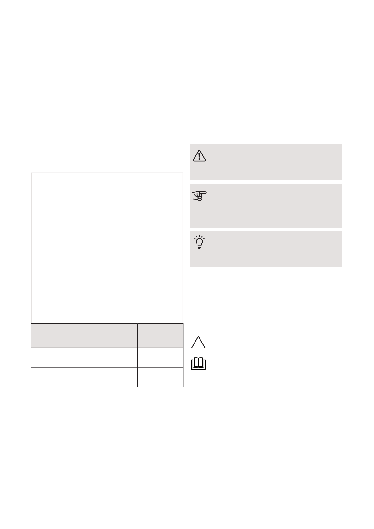
MinMaxSystem pres-
sure
0.05 MPa
(0.5 bar)
0.3 MPa
(3 bar)
Heating medium
0.01 MPa
(0.1 bar)
1.0 MPa
(10 bar)
Domestic water
Water may drip from the safety valve's
overflow pipe, so this pipe must be inclined
along its entire length to prevent water
pockets. It must also be frost-proof. The
overflow pipe must be visible and its outlet
must be open.
VVM 225 must be installed via an isolator
switch. The cable area has to be dimensioned
based on the fuse rating used.
Symbols
NOTE
This symbol indicates danger to person or ma-
chine .
Caution
This symbol indicates important information
about what you should consider when installing
or servicing the installation.
TIP
This symbol indicates tips on how to facilitate
using the product.
Marking
The CE mark is obligatory for most products sold in
the EU, regardless of where they are made.
CE
Classification of enclosure of electro-technical equip-
ment.
IPX1B
Danger to person or machine.
Read the User Manual.
NIBE VVM 225Chapter 1 | Important information4
1 Important information


 null")