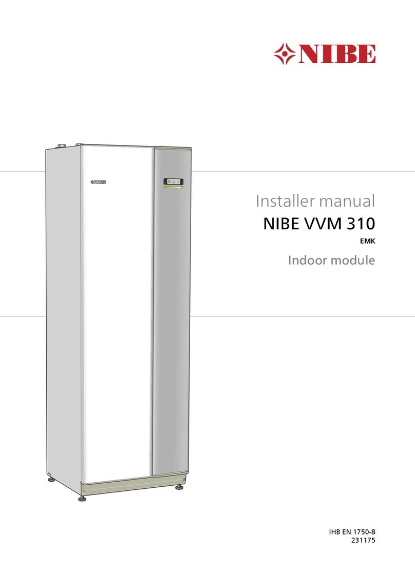
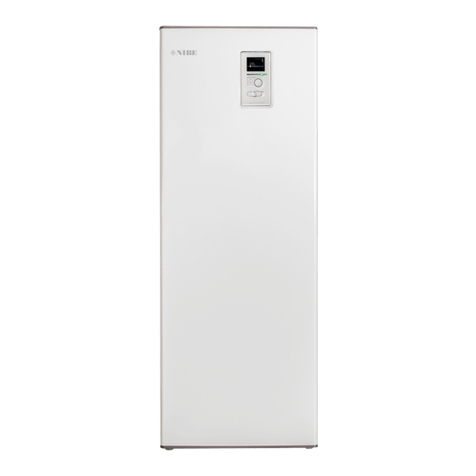
Nibe VVM 310 EMK User guide

Installer manual
APH
NIBE™ VVM 310
EMK
Indoor module
IHB GB 1705-7
231175

Quick guide
Navigation
Ok button (confirm/select)
Back button (back/undo/exit)
Control knob (move/increase/reduce)
A detailed explanation of the button functions can be found on page 39.
How to scroll through menus and make different settings is described on page 40.
Set the indoor climate
2X
MY INSTALLATION
INDOOR CLIMATE HOT WATER
INFO
The mode for setting the indoor temperature is accessed by pressing the OK button twice, when in the start mode
in the main menu.
Increase hot water volume
2X
1X INDOOR CLIMATE HOT WATER
MY INSTALLATION INFO
To temporarily increase the amount of hot water, first turn the control knob to mark menu 2 (water droplet) and
then press the OK button twice.
In event of disturbances in comfort
If a disturbance in comfort of any type occurs there are some measures that can be taken before you need to
contact your installer. See page 56 for instructions.

Table of Contents
41 Important information
4Safety information
72 Delivery and handling
7Transport
7Assembly
7Supplied components
8Removing the covers
93 Indoor module's design
114 Pipe connections
11General pipe connections
13Dimensions and pipe connections
14Installation alternative
225 Electrical connections
22General
25Connections
27Settings
29Optional connections
32Connecting accessories
336 Commissioning and adjusting
33Preparations
33Filling and venting
34Start-up and inspection
36Setting the cooling/heating curve
37Setting hot water circulation
37Pool
37SG Ready
397 Control - Introduction
39Display unit
40Menu system
438 Control - Menus
43Menu 1 - INDOOR CLIMATE
44Menu 2 - HOT WATER
44Menu 3 - INFO
45Menu 4 - MY SYSTEM
46Menu 5 - SERVICE
539 Service
53Service actions
5610 Disturbances in comfort
56Info menu indoor module
56Manage alarm
56Troubleshooting
5811 Accessories
6012 Technical data
60Dimensions and setting-out coordinates
61Hot water capacity
62Technical specifications
64Electrical circuit diagram, 3 x 400V
69Index
3Table of Contents |NIBE™ VVM 310

Safety information
This manual describes installation and service proced-
ures for implementation by specialists.
This appliance can be used by children
aged from 8 years and above and per-
sons with reduced physical, sensory or
mental capabilities or lack of experience
and knowledge if they have been given
supervision or instruction concerning
use of the appliance in a safe way and
understand the hazards involved. Chil-
dren shall not play with the appliance.
Cleaning and user maintenance shall
not be made by children without super-
vision.
Rights to make any design or technical
modifications are reserved.
©NIBE 2016.
Symbols
NOTE
This symbol indicates danger to machine or
person.
Caution
This symbol indicates important information
about what you should observe when main-
taining your installation.
TIP
This symbol indicates tips on how to facilitate
using the product.
Marking
VVM 310 is CE marked and fulfils IP21.
The CE marking means that NIBE ensures that the
product meets all regulations that are placed on it
based on relevant EU directives. The CE mark is obligat-
ory for most products sold in the EU, regardless where
they are made.
IP21 means that objects with a diameter larger than
or equivalent to 12.5 mm cannot penetrate and cause
damage and that the product is protected against
vertically falling drops of water.
Serial number
The serial number can be found to the left, on top of
VVM 310.
Serial number
Caution
Always give the product's serial number (14
digits) when contacting your installer.
Recovery
Leave the disposal of the packaging to the in-
staller who installed the product or to special
waste stations.
Do not dispose of used products with normal
household waste. It must be disposed of at a
special waste station or dealer who provides this type
of service.
Improper disposal of the product by the user results in
administrative penalties in accordance with current
legislation.
Country specific information
Installer manual
This installer manual must be left with the customer.
NIBE™ VVM 310Chapter 1 | Important information4
1 Important information

Inspection of the installation
Current regulations require the heating installation to be inspected before it is commissioned. The inspection must
be carried out by a suitably qualified person. Fill in the page for information about installation data in the User
manual.
DateSignatureNotesDescription
✔
Heating medium (page 16)
System flushed
System vented
Expansion vessel
Particle filter
Safety valve
Shut off valves
Boiler pressure
Connected according to outline diagram
Hot water (page 16)
Shut off valves
Mixing valve
Safety valve
Electricity (page 22)
Connected communication
Circuit fuses
Fuses, indoor module
Fuses property
Outside sensor
Room sensor
Current sensor
Safety breaker
Earth circuit-breaker
Setting of emergency mode thermostat
Miscellaneous
Docked to
5Chapter 1 | Important informationNIBE™ VVM 310

Contact information
KNV Energietechnik GmbH, Gahberggasse 11, 4861 SchörflingAT
Tel: +43 (0)7662 8963-0 Fax: +43 (0)7662 8963-44 E-mail: mail@knv.at www.knv.at
NIBE Wärmetechnik c/o ait Schweiz AG, Industriepark, CH-6246 AltishofenCH
Druzstevni zavody Drazice s.r.o, Drazice 69, CZ - 294 71 Benatky nad JizerouCZ
NIBE Systemtechnik GmbH, Am Reiherpfahl 3, 29223 CelleDE
Vølund Varmeteknik A/S, Member of the Nibe Group, Brogårdsvej 7, 6920 VidebækDK
NIBE Energy Systems OY, Juurakkotie 3, 01510 VantaaFI
NIBE Energy Systems France Sarl, Zone industrielle RD 28, Rue du Pou du Ciel, 01600 ReyrieuxFR
NIBE Energy Systems Ltd, 3C Broom Business Park, Bridge Way, Chesterfield S41 9QGGB
NIBE Energietechniek B.V., Postbus 634, NL 4900 AP OosterhoutNL
ABK AS, Brobekkveien 80, 0582 Oslo, Postadresse: Postboks 64 Vollebekk, 0516 OsloNO
NIBE-BIAWAR Sp. z o. o. Aleja Jana Pawła II 57, 15-703 BIAŁYSTOKPL
Tel: 085 662 84 90 Fax: 085 662 84 14 E-mail: sekretariat@biawar.com.pl www.biawar.com.pl
© "EVAN" 17, per. Boynovskiy, Nizhny NovgorodRU
NIBE AB Sweden, Box 14, Hannabadsvägen 5, SE-285 21 MarkarydSE
For countries not mention in this list, please contact Nibe Sweden or check www.nibe.eu for more information.
NIBE™ VVM 310Chapter 1 | Important information6

Transport
VVM 310 should be transported and stored vertically
in a dry place. However, the VVM 310 may be carefully
laid on its back when being moved into a building.
Assembly
■Position VVM 310 on a solid foundation that tolerates
water and the weight of the heat pump. Use the
product's adjustable feet to obtain a horizontal and
stable set-up.
30 - 50 mm
30 - 50 mm
15 - 40 mm
■Because water comes from VVM 310, the area where
the heating pump is located must be equipped with
floor drainage.
Installation area
Leave a free space of 800 mm in front of the product.
All service on VVM 310 can be carried out from the
front.
800
NOTE
Leave 10 – 25 mm free space between the in-
door module and the wall behind for routing
of cables and pipes.
Supplied components
Room sensorOutside sensor
LEK
LEK
LEK
Current sensor
Location
The kit of supplied items is placed on top of the
product.
7Chapter 2 | Delivery and handlingNIBE™ VVM 310
2 Delivery and handling

Removing the covers
Front cover
1
2
LEK
LEK
LEK
LEK
LEK
1. Remove the screws from the lower edge of the
front cover.
2. Lift the cover out at the bottom edge and up.
LEK
LEK
LEK
The side covers can be removed to facilitate the install-
ation.
NOTE
50 mm space required to remove the side
panels.
1. Remove the screws from the upper and lower
edges.
2. Twist the cover slightly outward.
3. Move the hatch backwards and slightly to the side.
4. Pull the cover to one side.
5. Pull the hatch forwards.
NIBE™ VVM 310Chapter 2 | Delivery and handling8

VVM 310
Wilo
Wilo
VVM 310
VVM 310
AA3
QM1
EB1
FD1
FA1
PF3
PF1
GP1
QM20
AA2
UB1
AA4-XJ4
AA4-XJ3
GP12
BT63
UB2
BF1*
BT6
BT54
XL30
AA7
XL18
XL3XL4
XL8
XL19
QN11
AA1-X3
BT30
AA1-X1
AA1-X7
AA1-S2
AA1
AA3-X4
BP5 QN35
UB1
UB2
K1
PF3
XL1
XL2
BT3
BT2
AA4
W130
SF1
QN10
BT7
XL9
PF1
PF4
*Applies to VVM 310 EMK. Available as accessory EMK 310 for other markets.
9Chapter 3 | Indoor module's designNIBE™ VVM 310
3 Indoor module's design

Pipe connections
Connection, heating medium supply line G20
int.
XL1
Connection, heating medium return line G20
int.
XL2
Connection, cold water G20 int.XL3
Connection, hot water G20 int.XL4
Connection, docking from heat pump G20 int.XL8
Connection, docking to heat pump G20 int.XL9
Connection, docking in high temp Ø22 mmXL18
Connection, docking out high temp Ø22 mmXL19
Connection, expansion tank G20 int.XL30
HVAC components
Circulation pumpGP1
Charge pumpGP12
Drain valve, climate systemQM1
Mixing valve, additionQN11
Venting, climate systemQM20
Reversing valve, climate system/water heating,
flow line
QN10
Reversing valve, climate system/water heating,
return line
QN35
Sensors etc.
Manometer, heating systemBP5
Temperature sensor, heating medium flow (not
visible in image)
BT2
Temperature sensor, heating medium return
(not visible in image)
BT3
Temperature sensor, hot water, chargingBT6
Temperature sensor, hot water, topBT7
Thermostat, standby modeBT30
Temperature sensor, external dockingBT54
Temperature sensor, heating medium supply
after immersion heater
BT63
Electrical components
Immersion heater cardAA1
AA1-S2 Switch (DIP switch) on circuit board
AA1-X1 Terminal block incoming
AA1-X3 Terminal block, immersion heater
AA1-X7 Terminal block, immersion heater
Base cardAA2
Input circuit boardAA3
AA3-X4 Terminal block, current sensors
Display unitAA4
AA4-XJ3 USB socket
AA4-XJ4 Service socket
Extra relay circuit boardAA7
Energy meterBF1*
Immersion heaterEB1
Miniature circuit-breakerFA1
Temperature limiterFD1
Auxiliary relay, emergency mode.K1
SwitchSF1
Network cable for NIBE UplinkTM
W130
Miscellaneous
Rating platePF1
Serial number platePF3
Sign, pipe connectionsPF4
Cable glandUB1
Cable glandUB2
Designations in component locations according to
standard IEC 81346-1 and 81346-2.
*Applies to VVM 310 EMK. Available as accessory EMK 310 for other markets.
NIBE™ VVM 310Chapter 3 | Indoor module's design10
General pipe connections
Pipe installation must be carried out in accordance with
current norms and directives.
The system requires the radiator circuit to be designed
for a low temperature heating medium. At lowest di-
mensioned outdoor temperature, the highest recom-
mended temperatures are 55 °C on the supply line and
45 °C on the return line, but VVM 310 can handle up
to 65 °C.
NOTE
Equip the product with a safety valve on both
the boiler side and domestic coil.
Overflow water from the safety valve goes via overflow
cups to a drain so that hot water splashes cannot cause
injury. The entire length of the overflow water pipe
must be inclined to prevent water pockets and must
also be frost proof.
NIBE recommends installing VVM 310 as close to the
heat pump as possible for optimum comfort. For further
information about the location of different compon-
ents, see section "Installation alternatives" in this
manual.
NOTE
Any high points in the climate system, must
be equipped with air vents.
NOTE
The pipe systems need to be flushed out be-
fore the indoor module is connected so that
any debris cannot damage component parts.
NOTE
Switch (SF1) must not be moved to "" or " "
until VVM 310 has been filled with water.
Otherwise the temperature limiter, thermostat
and the immersion heater etc can be dam-
aged.
Boiler and radiator volumes
H
Internal volume in VVM 310
for calculating expansion
vessel is 250 l. The expansion
vessel's volume must be at
least 5 % of the system's total
volume.
Example table
Volume (l)
expansion
vessel
Total
volume (l)
(indoor
module and
climate sys-
tem)
25500
Volume (l) expansion
vessel
Total volume (l) (indoor
module and climate sys-
tem)
35700
501,000
NOTE
Expansion vessel not supplied with the
product. Equip the product with an expansion
vessel.
The pre-pressure of the pressure expansion vessel must
be dimensioned according to the maximum height (H)
between the vessel and the highest positioned radiator,
see figure. A pre-pressure of 0.5 bar (5 mvp) means a
maximum permitted height difference of 5 m.
If the standard initial pressure in the pressure vessel is
not high enough it can be increased by filling via the
valve in the expansion vessel. The expansion vessel's
standard initial pressure must be entered in the check
list on page 5.
Any change in the initial pressure affects the ability of
the expansion vessel to handle the expansion of the
water.
System diagram
VVM 310 consists of domestic coil for water heating,
immersion heater, circulation pumps, buffer vessel and
control system. VVM 310 connects to the climate sys-
tem.
VVM 310 is designed for connection and communica-
tion with F2020/F2025/F2026/F2030/F2040/F2120,
which together make up a complete heating installa-
tion.
When it is cold outdoors
F2020/F2025/F2026/F2030/F2040/F2120 works with
VVM 310 and if the outdoor air temperature falls below
the heat pump stop temperature, all heating is carried
out by VVM 310.
-EB15-FL2
-EB15
-CM1
-EB15
-FL1
-QM40-RM1
-EB101
-XL2
-XL1 -HQ1
-QM1
-QM41
-FL10
-QM40
-EB101
11Chapter 4 | Pipe connectionsNIBE™ VVM 310
4 Pipe connections

Symbol key
MeaningSymbol
Venting valve
Shut-off valve
Tapping valve
Non-return valve
Trim valve
Shunt / shuttle valve
Safety valve
Thermometer
T
Temperature sensor
Expansion vessel
Pressure gauge
P
Circulation pump
Particle filter
Particle filter
Fan
Flow meter EMK 310
Compressor
Heat exchanger
Radiator system
Domestic hot water
Under floor heating systems
NIBE™ VVM 310Chapter 4 | Pipe connections12

Dimensions and pipe
connections
20
1780
560
600
355
245
615
95
185
215
30-50
80
135
190
80
135
190
300
XL1
XL30XL2
XL18
XL3XL4 XL9
XL8
XL19
PF1
PF3
XL13
XL14
20
1780
560
600
355
245
615
95
185
215
30-50
80
135
190
80
135
190
300
Pipe connections
Connection, heating medium supply line G20
int.
XL1
Connection, heating medium return line G20
int.
XL2
Connection, cold water G20 int.XL3
Connection, hot water G20 int.XL4
Connection, docking in heating medium G20
int.
XL8
Connection, docking out heating medium G20
int.
XL9
Connection, solar heating system supply line
Ø22 mm
XL13
Connection, solar heating system return line
Ø22 mm
XL14
Connection, docking in high temp Ø22 mmXL18
Connection, docking out high temp Ø22 mmXL19
Connection, expansion tank G20 int.XL30
13Chapter 4 | Pipe connectionsNIBE™ VVM 310

Installation alternative
Compatible NIBE air/water heat pumps
Compatible NIBE air/water heat pumps must be
equipped with a control card with display that has the
software version given in the following list as a minim-
um. The control card version is displayed in the heat
pump's display upon start-up.
Software versionProduct
118F2020
55F2025
55F2026
all versionsF2030
all versionsF2040
all versionsF2120
VVM 310 can be connected to extra water heater, see
below.
Further option information is available at www.nibe.eu
and in the respective assembly instructions for the ac-
cessories used. See page 58 for a list of the accessories
that can be used with VVM 310.
Extra hot water heaters
Water heater with immersion heater
If it is possible to use a water heater with an immersion
heater, NIBE COMPACT or EMINENT type water heaters
can be used.
If the valve connector is to be installed externally,
moved out or separated, it must be replaced with a
separable connector Ø 22 mm.
HW fromVVM 310
NIBE™ VVM 310Chapter 4 | Pipe connections14

Explanation
Exhaust air heat pump F135AZ10
Particle filterHQ1
Shut-off valveQM42
Shut-off valveQM43
Shut-off valveQM44
Non-return valveRM1
Pool kitCL11
Unit boxAA25
Temperature sensor, poolBT51
Exchanger, poolEP5
Pool, pumpGP9
Charge pumpGP12
Particle filterHQ4
Three way valve, poolQN19
VVM 310EB15
Energy meterBF1*
Expansion vessel closed, heating mediumCM1
Safety valve, heating mediumFL2
Connection, heating medium, flow 1XL1
Connection, heating medium, return 1XL2
Connection, cold waterXL3
Connection, hot waterXL4
Connection, docking, from heat pumpXL8
Connection, docking, to heat pumpXL9
Connection, solar heating system, supplyXL13
Connection, solar heating system, returnXL14
Connection, docking in high tempXL18
Connection, docking out high tempXL19
Connection, accessory, outXL39
Heat pumpEB101
Safety valveFL10
Particle filterHQ1
Tapping valveQM1
Shut-off valveQM40
Shut-off valveQM41
External heat source (Oil, gas, pellets or wood
fired boiler with shunt valve)
EM1
Unit box with accessory cardAA25
Temperature sensor, boilerBT52
Charge pump, external heat sourceGP15
Non-return valveRM1
Climate system 2EP21
Unit box with accessory cardAA25
Temperature sensor, heating medium, flowBT2
Temperature sensor, heating medium, returnBT3
Circulation pump, heating medium, lower shuntGP20
Shunt valveQN25
Solar kitEP30
Unit box with accessory cardAA25
Temperature sensor, solar panelBT53
Expansion vesselCM5
Solar panelEP8
Pump station SPS 10, SPS20GP30
Active cooling module ACS 310EQ1
Unit box with accessory cardAA25
Temperature sensor, cooling, supply lineBT64
Single jacket accumulator tank, coolingCP10
Charge pumpGP12
Circulation pump, coolingGP13
Three way valve cooling/heatingQN12
Pump station SPS 10, SPS 20GP30
Safety valve, solarFL4
Pump, solarGP4
Shut-off valveQM43
Shut-off valveQM44
Shut-off valveQM45
Non-return valveRM3
Non-return valveRM4
Hot water circulation
Safety valve, hot waterFL1
Circulation pump, Hot waterGP11
Shut-off valveQM40
Non-return valveRM1
Miscel-
laneous
Flow sensor EMK 310BF1
Flow sensor EMK 300BF2
Expansion vessel closed, heating mediumCM1
Electric heater ELKEB1
Exchanger, poolEP5
Safety valve, heating mediumFL2
Pump, solarGP4
*Energy meter (BF1) included in VVM 310 EMK.
15Chapter 4 | Pipe connectionsNIBE™ VVM 310

Connecting to heat pump
All outdoor pipes must be thermally insulated with at
least 20 mm thick pipe insulation.
VVM 310 is not equipped with shut off valves; these
must be installed outside the indoor module to facilit-
ate any future servicing.
-EB15-FL2
-EB15
-CM1
-EB15
-XL8
-XL9
-EB101
-XL2
-XL1 -HQ1
-QM1
-QM41
-FL10
-QM40
-EB101
Connection during use without heat pump
Connect the pipe for docking in from the heat pump
(XL8) with the pipe out to the heat pump XL9.
-EB15-FL2
-EB15
-CM1
-EB15
-XL8 -XL9
Connecting cold and hot water
The mixer valve must be installed if the factory setting
is changed so that the temperature can exceed 60 °C.
If the factory setting is changed, national regulations
must be observed. The setting is made in menu 5.1.1 (
See page 47).
-EB15-FL2
-XL4
-XL3
-EB15
-CM1
-EB15
-FL1
-QM40-RM1
Connecting the climate system
When connecting to a system with thermostats on all
radiators/underfloor heating coils, a relief valve must
be fitted, or a thermostat must be removed to ensure
sufficient flow.
-EB15-FL2
-EB15
-CM1
-EB15
-XL1
-XL2
NIBE™ VVM 310Chapter 4 | Pipe connections16

Two or more climate systems
When more than one climate system is to be heated,
the following connection can be used.
The ECS 40/ECS 41. accessory is required for this con-
nection.
-EB15-FL2
-EB15
-EB15
-CM1 -XL1
-XL2
-GP20
-BT3
-BT2
-QN25
-EP21
-AA25
Connection of external heat source
For connection to a gas/electric/oil boiler, the DEH 310
accessory is required, see "Accessories" on page 58.
-EB15-FL2
-EB15
-CM1
-EB15
-XL18
-XL19
-BT52
-EM1
-AA25
-EM1
-GP15
-RM1
Connection of extra electrical addition
For connection of extra electrical addition, in one step,
in event of a stoppage because of cold outdoor air.
-EB15-FL2
-EB15
-CM1
-EB15
-XL8
-XL9
-EB101
-XL2
-XL1 -HQ1
-QM1
-QM41
-FL10
-QM40
-EB101
-EB15-EB1
Connecting EMK 310
Installing energy measurement kit EMK 310* (BF1) to
VVM 310.
-EB15-FL2
-EB15
-CM1
-EB15
-XL8
-XL9
-EB101
-XL2
-XL1 -HQ1
-QM1
-QM41
-FL10
-QM40
-EB101
-EB15
-BF1
*Energy meter (BF1) included in VVM 310 EMK. Available as ac-
cessory EMK 310 for other markets.
Connecting EMK 300
Installing energy measurement kit EMK 300 (BF2) to
VVM 310. This accessory is used if energy measurement
of pool or 4-pipe cooling is required.
-EB15
-FL2
-EB15
-CM1
-EB15
-XL8
-XL9
-EB101
-XL2
-XL1 -HQ1
-QM1
-QM41
-FL10
-QM40
-EB101
-EB15-BF2
-GP9 -BT51 -HQ4
-EP5
-AA25
-CL11
-CL11-QN19
-CL11
-GP12
17Chapter 4 | Pipe connectionsNIBE™ VVM 310

Connecting hot water circulation
To reduce the risk of bacterial growth in systems with
hot water circulation, the temperature of the circulating
water should not fall below 50 °C. There should not be
any non-circulatory hot water pipes. Adjust the hot
water system so that the temperature does not fall
below 50 °C at the ends of the system.
-FL2
-CM1
-EB15
-EB15
-FL1
-QM40-RM1
-GP11
XL3
XL4
Connecting ACS 310
For connection of active cooling, ACS 310, see "Accessor-
ies" on page 58.
-EB15-FL2
-EB15
-CM1
-EB15
-EB101
-XL2
-XL1 -HQ1
-QM1
-QM41
-FL10
-QM40
-EB101
-CP10
-BT64 -QN12
-AA25
-EQ1
-GP13
-GP12
Connecting to solar installation
For connection to solar installation, the SCA 35 accessory is required, see "Accessories" on page 58.
TPT
-FL2
-CM1
-XL13
-XL14
-EB15
-EB15
-EP30
-BT53
-EP8
-EB101
-FL10
-AA5
-GP30
-RM4
-GP4 -EP5
-RM3
-GP4
-CM5
-FL4
-OM44
-OM43
-OM45
-XL1
-XL2
-QM40
-HQ1 -QM41
-QM1
NIBE™ VVM 310Chapter 4 | Pipe connections18

Connecting pool
Charging of the pool is controlled by the pool sensor. In the case of low pool temperatures, the reversing valve reverses
direction and opens towards the pool exchanger. The POOL 310 accessory is required for this connection.
-EB15
-FL2
-EB15
-CM1
-EB15
-EB101
-XL2
-XL1 -HQ1
-QM1
-QM41
-FL10
-QM40
-EB101
-GP9 -BT51 -HQ4
-EP5
-AA25
-CL11
-CL11-QN19
-CL11
-GP12
Connecting F135
The demand on F135 is controlled by the indoor module in the system. The pump and fan speed are also controlled
from the menu in the indoor module.
-EB15-FL2
-EB15
-CM1
-EB15
-EB101
-XL2
-XL1 -HQ1
-QM1
-QM41
-FL10
-QM40
-EB101
-AZ10
-AZ10
-HQ1 -GP10
-QM42 -QM43
-RM1
19Chapter 4 | Pipe connectionsNIBE™ VVM 310

Connection of F135, ACS 310 and pool
F135 connected in air/water system with 4-pipe cooling. 4-pipe cooling must in this instance be connected between
the outdoor air heat pump and F135. Where there is also a pool, F135 must be connected between 4-pipe cooling
and pool. The demand on F135 is controlled by the indoor module in the system. The pump and fan speed are also
controlled from the menu in the indoor module.
-EB15
-FL2
-EB15
-CM1
-EB15
-EB101
-XL2
-XL1 -HQ1
-QM1
-QM41
-FL10
-QM40
-EB101
-GP9 -BT51 -HQ4
-EP5
-AA25
-CL11
-CL11
-QN19
-CL11
-GP12
-CP10
-BT64 -QN12
-AA25
-EQ1
-GP13
-GP12
-AZ10
-AZ10
-RM1
-QM44
-HQ1 -GP10
-QM42 -QM43
NIBE™ VVM 310Chapter 4 | Pipe connections20
Other manuals for VVM 310 EMK
2
This manual suits for next models
1
Table of contents
Other Nibe Air Conditioner manuals

Nibe
Nibe ACS 45 User guide

Nibe
Nibe ACS 45 User guide

Nibe
Nibe BA-SVM 10-200 Series User manual

Nibe
Nibe Climate Master RGED Series User manual

Nibe
Nibe FLM User guide

Nibe
Nibe ACVM 270 User manual

Nibe
Nibe AG-WT10-4 User manual

Nibe
Nibe VVM 310 EMK User guide

Nibe
Nibe AMB 30 User manual

Nibe
Nibe VVM 225 User guide
Popular Air Conditioner manuals by other brands

Celair
Celair Profile Series owner's manual

NEC
NEC RIH-6867 user manual

Soleus Air
Soleus Air GB-PAC-08E4 operating instructions

Mitsubishi Electric
Mitsubishi Electric MSC-GE20VB operating instructions

Mitsubishi Electric
Mitsubishi Electric Mr. Slim PUZ-M200YKA2.UK Service manual

Sanyo
Sanyo CH0971 Technical & service manual