Nibe AG-WT10-4 User manual

Document Number: 38-9007-142 Revision: 02
S.A.C.
S.r.l.
Sede Legale: Via Varese, 90
Società a socio unico
I - 21013Gallarate (VA) Telefono: +390331755111
Fax: +390331 784513 Codice Fiscale e R.I. Varese 08930800159
Capitale Sociale Euro 8.287.000 Partita IVAIT01982420125
REAN. 221925 - Varese
Technical manual
NIBE AG-WT10
Air to air indoor unit

Document Number: 38-9007-142 Revision: 02
S.A.C.
S.r.l.
Sede Legale: Via Varese, 90
Società a socio unico
I - 21013Gallarate (VA) Telefono: +390331755111
Fax: +390331 784513 Codice Fiscale e R.I. Varese 08930800159
Capitale Sociale Euro 8.287.000 Partita IVAIT01982420125
REAN. 221925 - Varese
TABLE OF CONTENTS
1SCOPE...................................................................................................................................4
2TECHNICAL SPECIFICATIONS .....................................................................................5
3REFRIGERANT CIRCUIT AND SENSORS POSITION .............................................6
4ELECTRICAL WIRING DIAGRAM .................................................................................7
5PRINCIPLE OF FUNCTIONING.....................................................................................9
6COMPONENTS OPERATION.........................................................................................10
7REMOTE CONTROLLER SETTINGS AND FUNCTIONS .........................................12
8COMPONENT DESCRIPTION .......................................................................................14
9TROUBLESHOOTING......................................................................................................16
10 COMPONENT REPLACEMENT ......................................................................................18
11 PAC AGING......................................................................................................................47
12 RATING LABELS ..............................................................................................................49

Document Number: 38-9007-142 Revision: 02
S.A.C.
S.r.l.
Sede Legale: Via Varese, 90
Società a socio unico
I - 21013Gallarate (VA) Telefono: +390331755111
Fax: +390331 784513 Codice Fiscale e R.I. Varese 08930800159
Capitale Sociale Euro 8.287.000 Partita IVAIT01982420125
REAN. 221925 - Varese
REVISION NOTES
Rev.
Date Author Checked Comments
00 26/09/20 4
MDG AG First release.
0 7/ 0/20 4
MDG AG Updated some values under “Technical specifications”
section.
02 25/ /20 4
AG MDG Added model AG-WT 0-7. Added Scope, Packaging and
Rating Labels sections.

Document Number: 38-9007-142 Revision: 02
S.A.C.
S.r.l.
Sede Legale: Via Varese, 90
Società a socio unico
I - 21013Gallarate (VA) Telefono: +390331755111
Fax: +390331 784513 Codice Fiscale e R.I. Varese 08930800159
Capitale Sociale Euro 8.287.000 Partita IVAIT01982420125
REAN. 221925 - Varese
1Scope
This specification document is applied to the indoor units mentioned below used for air to air heat pump
to be delivered to NIBE AB.
UNIT MODEL TABLE
NIBE ARGO* Model number
AG-WT 0-4 AWIAS 3 069 33
AG-WT 0-7 AWIBS 3 069 34
* cross reference with similar ARGO models.
DECLARATION OF CONFORMITY “CE”
Units described in this document conform to the protection requirement of the following EC directives:
•EMC Directive 2004/ 08/EC
•LVD (Low Voltage Directive) 2006/95/EC
•RoHS 2 Directive 20 /65/EU
Standards:
•EN378-2:2008 + A :2009
•EN 60335- :2002+A :2004+A 2:2006+A 3:2008+A 4:20 0
•EN 60335-2-40 :2003+A :2004+A 2:2009+A :2006
•EN 550 4- :2006 + A :2009
•EN 550 4-2: 997 + A :200 + A2:2008
•EN 6 000-3-2:2006+A :2009+A2:2009
•EN 6 000-3-3:2008
•EN 6 000-3- :2000
•EN 6 000-3- 2:2005

Document Number: 38-9007-142 Revision: 02
S.A.C.
S.r.l.
Sede Legale: Via Varese, 90
Società a socio unico
I - 21013Gallarate (VA) Telefono: +390331755111
Fax: +390331 784513 Codice Fiscale e R.I. Varese 08930800159
Capitale Sociale Euro 8.287.000 Partita IVAIT01982420125
REAN. 221925 - Varese
2Technical specifications
AG-WT10-4
Features Unit Value
Airflow rate (el.-l.-m.-h.) m³/h 330-460-540-660
Dehumidification l/h ,5
Fan speeds n° Auto + 3 remote control
settings
Sound pressure (el.-l.-m.-h.) dB(A) 25-3 -39-42
Power supply V/Ph/Hz
230/ /50
Power input kW 0,046
Liquid pipe diameter mm (") 6,35( /4")
Gas pipe diameter mm (") 9,52(3/8")
Net weight kg 0
Net dimension (H./W./D.) mm 289x845x209
AG-WT10-7
Features Unit Value
Airflow rate (el.-l.-m.-h.) m³/h 520-6 0-720-800
Dehumidification l/h 2,0
Fan speeds n° Auto + 3 remote control
settings
Sound pressure (el.-l.-m.-h.) dB(A) 36-39-42-46
Power supply V/Ph/Hz
230/ /50
Power input kW 0,079
Liquid pipe diameter mm (") 6,35( /4")
Gas pipe diameter mm (") 2,7( /2")
Net weight kg 3,5
Net dimension (H./W./D.) mm 300x970x224

Document Number: 38-9007-142 Revision: 02
S.A.C.
S.r.l.
Sede Legale: Via Varese, 90
Società a socio unico
I - 21013Gallarate (VA) Telefono: +390331755111
Fax: +390331 784513 Codice Fiscale e R.I. Varese 08930800159
Capitale Sociale Euro 8.287.000 Partita IVAIT01982420125
REAN. 221925 - Varese
3Refrigerant circuit and sensors position
Note:
-In heating mode the refrigerant flow is in the opposite direction of the COOL arrows
-ICT: Indoor Coil Sensor
-RAT: Room Air Sensor

Document Number: 38-9007-142 Revision: 02
S.A.C.
S.r.l.
Sede Legale: Via Varese, 90
Società a socio unico
I - 21013Gallarate (VA) Telefono: +390331755111
Fax: +390331 784513 Codice Fiscale e R.I. Varese 08930800159
Capitale Sociale Euro 8.287.000 Partita IVAIT01982420125
REAN. 221925 - Varese
4Electrical wiring diagram
Legend
A Main control pcb
TH2 Room Air Sensor (RAT)
A2 LEDs & Infrared Receiver pcb
TH Outdoor Coil Sensor (ICT)
F Main Fuse
3, 5A / 250V
EVAP Heat exchanger
F2 Communication Fuse, RS485 bus
00mA / 250V
FLP Flap stepper motor
SW -SW3 Dip-switch
FMI Fan motor
JP /2/3/4 Jumpers
J 3 On-Off jumper

Document Number: 38-9007-142 Revision: 02
S.A.C.
S.r.l.
Sede Legale: Via Varese, 90
Società a socio unico
I - 21013Gallarate (VA) Telefono: +390331755111
Fax: +390331 784513 Codice Fiscale e R.I. Varese 08930800159
Capitale Sociale Euro 8.287.000 Partita IVAIT01982420125
REAN. 221925 - Varese
Settings
Dip-switch settings can be changed only when unit is powered off.
Jumpers
JP : Factory use. Default: open.
JP2: Factory use. Default: open.
JP3: Factory use. Default: closed.
JP4: Factory use. Default: open.
On-Off contact (J13)
-Closed: unit operates according to the remote controller settings. Factory default.
-Open: unit is always switched off.
Dip-switch
SW : Communication address setting:
-Circuit A: =Off, 2=Off (factory default)
-Circuit B: =ON, 2=Off
-Circuit C: =Off, 2=ON
-Circuit D: =ON, 2=ON
Note: For single split system, leave SW in default position (circuit A).
SW3: Remote Controller channel selection:
Channel Remote controller Indoor unit main pcb

Document Number: 38-9007-142 Revision: 02
S.A.C.
S.r.l.
Sede Legale: Via Varese, 90
Società a socio unico
I - 21013Gallarate (VA) Telefono: +390331755111
Fax: +390331 784513 Codice Fiscale e R.I. Varese 08930800159
Capitale Sociale Euro 8.287.000 Partita IVAIT01982420125
REAN. 221925 - Varese
5Principle of functioning
Heating mode
When the unit is in heating mode, the system will regulate the heating capacity delivered to the room to
increase the room air temperature (RAT) to the set point (SPT) and to balance the thermal load of the
room to keep the set point temperature.
Cooling mode
When the unit is in cooling mode, the system will regulate the cooling capacity delivered to the room to
decrease the room air temperature (RAT) to the set point (SPT) and to balance the thermal load of the
room to keep the set point temperature.
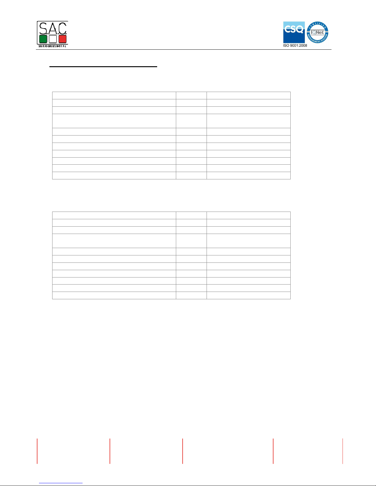
Dehumiditication (dry) mode
When the unit is in dry mode, the system will operate according to the following table:
Note: when dry mode is active, the temperature of the room could decrease below the setpoint
temperature if the thermal load of the room is low.
Auto mode
When the unit is in auto mode (auto cooling or auto heating), the system will switch between heating
and cooling mode to maintain the room air temperature (RAT) to the set point temperature (SPT).
The system will switch between heating and cooling mode if one of the following conditions is met:
-Cooling Heating if at least 3 minutes have passed since the compressor was stopped and ∆T ≤ -3
-Cooling Heating if at least hour have passed since the compressor was stopped and ∆T ≤ -
-Heating Cooling if at least 3 minutes have passed since the compressor was stopped and ∆T ≥ 3
-Heating Cooling if at least hour have passed since the compressor was stopped and ∆T ≥
where:
∆T = RAT – SPT
Fan mode
During fan mode, compressor is stopped and indoor fan will run at the selected speed.
RAT DRY LEVEL DESCRIPTION
≥ SPT + 2°C 0 Unit operates normally in cooling mode.
< SPT + 2°C
≥ SPT - °C
Unit operates with a fixed cooling demand.
Indoor fan switches between very low speed and
low speed every 30 seconds.
< SPT - °C
≥ 0°C 2
Unit cycles between a period of operation with a
fixed cooling demand (3 minutes) and a period of
non operation (9 minutes).
Indoor fan switches between very low speed and
low speed every 30 seconds.
< 0°C DRY OFF Unit is off.

Document Number: 38-9007-142 Revision: 02
S.A.C.
S.r.l.
Sede Legale: Via Varese, 90
Società a socio unico
I - 21013Gallarate (VA) Telefono: +390331755111
Fax: +390331 784513 Codice Fiscale e R.I. Varese 08930800159
Capitale Sociale Euro 8.287.000 Partita IVAIT01982420125
REAN. 221925 - Varese
6Components operation
Indoor Fan
When unit is switched on, indoor fan runs at the speed selected on the remote controller.
Auto fan speed
If Auto Fan speed is selected, the fan speed will be managed according to the graph below:
where TL is the thermal load of the room calculated by the controller.
Cold Draft protection
When unit is in heating mode, fan speed could be limited or stopped to prevent cold air drafts from the
heat exchanger when heat exchanger is not warm enough.
In this case, fan speed is managed accorging to the graph below:
(*): Values can vary based on “dynamic cold draft” algorithm.
MIN
Fan speed
3 °C
Remote controller set
0
ICT (
*)
37°C
MIN
Fan speed
0
LOW
HIGH
TL
MAX

Document Number: 38-9007-142 Revision: 02
S.A.C.
S.r.l.
Sede Legale: Via Varese, 90
Società a socio unico
I - 21013Gallarate (VA) Telefono: +390331755111
Fax: +390331 784513 Codice Fiscale e R.I. Varese 08930800159
Capitale Sociale Euro 8.287.000 Partita IVAIT01982420125
REAN. 221925 - Varese
Flap motor
Flap will be positioned according to the remote controller settings.
If Auto Swing or Full Swing option is selected, flap will be moved with a lower speed in order to better
distribute the air in the room.
If Auto Swing is selected:
-In cooling or dry mode, the flap will address the air to the upper part of the room
-In heating, the flap will address the air to the lower part of the room
Air ionizer
Air ionizer is activated or deactivated according to the remote controller setting.

Document Number: 38-9007-142 Revision: 02
S.A.C.
S.r.l.
Sede Legale: Via Varese, 90
Società a socio unico
I - 21013Gallarate (VA) Telefono: +390331755111
Fax: +390331 784513 Codice Fiscale e R.I. Varese 08930800159
Capitale Sociale Euro 8.287.000 Partita IVAIT01982420125
REAN. 221925 - Varese
7Remote controller settings and functions
Infrared transmitter frequency setting
The infrared frequency of the remote controller must be set to 38kHz to work properly with the indoor
unit. Is the frequency is not set, transmitting distance is reduced.
To set the correct frequency on the remote controller, follow this procedure:
Important: this procedure must be repeated every time batteries are changed.
IFeel
IFeel OFF
When IFeel is off, the unit controls the temperature of the room based on the value of the internal air
sensor.
If the unit is in heating mode, a heating shift is applied to the value read by the sensor. For example, it
the sensor reads 25°C, the actual temperature will be 22°C. The heating shift is indoor unit dependent.
IFeel ON, Remote Controller inside the range of the infrared receiver
In this case the unit controls the temperature of the room based on the value of the sensor of the
remote controller.
IFeel ON, Remote Controller outside the range of the infrared receiver
This condition occurs when IFeel is ON and the indoor unit doesn’t receive any signal from the remote
controller for more than 0 minutes, and lasts until a new signal is received from the remote. In this
case, the unit will control the temperature of the room based on the internal sensor and applying a
correction that depends on the difference between the last read temperature from the remote controller
and the internal sensor temperature at that moment, until a new signal is received from the remote
controller or IFeel is switched OFF.

Document Number: 38-9007-142 Revision: 02
S.A.C.
S.r.l.
Sede Legale: Via Varese, 90
Società a socio unico
I - 21013Gallarate (VA) Telefono: +390331755111
Fax: +390331 784513 Codice Fiscale e R.I. Varese 08930800159
Capitale Sociale Euro 8.287.000 Partita IVAIT01982420125
REAN. 221925 - Varese
Important: when IFeel mode is active, in order to have the best efficiency and fine control of the room
temperature:
-Leave the remote controller inside the range of the unit, where it can send clear signal to the unit.
-Don’t leave the remote controller under the airflow of the unit.
-Be sure that the batteries of the remote controller have a good charge.
-Be sure to have set the remote controller with 38kHz frequency.
Night Mode
When Night Mode is activated, fan speed is automatically reduced. hour after the Night Mode has been
activated, the setpoint of the unit will change according to the following table:
Heating mode Cooling or Dry Mode
Decresed by 2°C Increased by °C
To come back to the original setpoint, disable the Night Mode option.
High Power Mode (Turbo Mode)
When High Power Mode is activated:
-The unit will run to deliver the maximum capacity
-Indoor fan speed is increased to the maximum speed
Notes:
-If High Power Mode is active together with Night Mode, High Power Mode will prevail.
-High Power Mode remains active until it will be deactivated with the remote controller.
-During the high power operation the room temperature could not correspond to the set
temperature.

Document Number: 38-9007-142 Revision: 02
S.A.C.
S.r.l.
Sede Legale: Via Varese, 90
Società a socio unico
I - 21013Gallarate (VA) Telefono: +390331755111
Fax: +390331 784513 Codice Fiscale e R.I. Varese 08930800159
Capitale Sociale Euro 8.287.000 Partita IVAIT01982420125
REAN. 221925 - Varese
8Component description
Fan motor
AG-WT10-4 AG-WT10-7
Rated voltage 220-240V ~ 220-240V ~
Rated frequency 50 Hz 50 Hz
Number of poles 4 4
Insulation class E E
Rated power 20 W 50 W
Main:2 0±8% Ω Main:33±8% Ω
Resistance of enamel wire
(at 20°C) Aux: 360±8%Ω Aux: 33±8%Ω
Input current (No load) 92± 0% mA 97± 0% mA
Flap motor
AG-WT10-4 AG-WT10-7
Rated voltage 2V DC 2V DC
Number of phase 4 4
Insulation class E E
Resistance per phase (at
25°C) 200±7% Ω 30±7% Ω
Minimum static detent
torque 0.034 N•m 0. 7 N•m
Ion Generator
Rated voltage 220-240V ~ 50/60Hz
Power < 2W
Input current < 2mA
+ .2±0.6 V
Ion generating voltage (at
20°C) - 2.2±0.6 V

Document Number: 38-9007-142 Revision: 02
S.A.C.
S.r.l.
Sede Legale: Via Varese, 90
Società a socio unico
I - 21013Gallarate (VA) Telefono: +390331755111
Fax: +390331 784513 Codice Fiscale e R.I. Varese 08930800159
Capitale Sociale Euro 8.287.000 Partita IVAIT01982420125
REAN. 221925 - Varese
Sensors
ICT: Indoor Coil Temperature. Used for:
-EEV management at the outdoor unit
-Fan management
-Protection against overheating of the heat exchanger (heating mode)
-Protection against freeze up of the heat exchanger (cooling or dry mode)
RAT: Room Air Temperature. Used for:
-Thermal load calculation
-Fan management
T RAT ICT
[°C] Resistance
[Kohm] Voltage
[Vdc] Resistance
[Kohm] Voltage
[Vdc]
-20 131,090 2,158 192,000 2,173
-15 101,342 2,068 145,000 2,080
-10 78,585 1,962 110,300 1,972
-5 61,162 1,843 84,610 1,849
0 47,800 1,712 65,370 1,715
5 37,527 1,572 50,870 1,572
10 29,606 1,427 39,870 1,424
15 23,477 1,280 31,470 1,276
20 18,715 1,137 25,010 1,131
25 15,000 1,000 20,000 0,994
30 12,088 0,873 16,100 0,867
35 9,795 0,756 13,040 0,751
40 7,980 0,652 10,620 0,648
45 6,537 0,560 8,705 0,557
50 5,382 0,480 7,173 0,477
55 4,454 0,411 5,942 0,409
60 3,704 0,351 4,948 0,350
65 3,094 0,300 4,140 0,299
70 2,596 0,257 3,481 0,257
75 2,187 0,220 2,940 0,220
80 1,849 0,188 2,495 0,189
85 1,569 0,162 2,125 0,163

Document Number: 38-9007-142 Revision: 02
S.A.C.
S.r.l.
Sede Legale: Via Varese, 90
Società a socio unico
I - 21013Gallarate (VA) Telefono: +390331755111
Fax: +390331 784513 Codice Fiscale e R.I. Varese 08930800159
Capitale Sociale Euro 8.287.000 Partita IVAIT01982420125
REAN. 221925 - Varese
9Troubleshooting
Error
Meaning System behaviour Solution
E Error on the outdoor unit Fan is stopped and flap is
closed.
The system restarts
automatically as soon as the
problem on the outdoor unit
is solved.
Check the error code using the appropriate
LEDs on the PCB of the outdoor unit. Follow
the indications of the diagnosis for the
outdoor unit.
Check that connections between C and C2
on outdoor and indoor terminal block is
consistent (C terminals connected
together, C2 terminals connected
together).
Check that a shielded communication cable
for serial connection has been used.
Verify that the dip-switch SW for
communication address setting is in the
correct position.
Check that earth cables are properly
connected to every terminal.
Check that the shield of the communication
cable is properly connected to every
terminal.
Chech that all internal earth cable are
properly connected.
Check the communication fuse on outdoor
unit.
Check the communication fuse on indoor
unit.
Check that the outdoor unit has power
supply and that the unit is working.
Check that all the pcbs are powered on.
Be sure that power supply has not been
connected to the communication terminals.
Check that there are no burnt signes on the
pcbs, in particular close to communication
cables.
E3 Communication error
between the outdoor unit
and the indoor unit.
Fan is stopped and flap is
closed after 30 seconds of
missing communication.
The system restarts
automatically as soon as the
communication is recovered.
Check that the fan motor is not damaged
and doesn’t create short circuit on the
indoor pcb.
E4 ICT (Indoor Coil
Temperature) sensor fault.
Fan is stopped and flap is
closed.
The system restarts as soon
as the sensor is repaired.
Reconnect or replace the sensor.

Document Number: 38-9007-142 Revision: 02
S.A.C.
S.r.l.
Sede Legale: Via Varese, 90
Società a socio unico
I - 21013Gallarate (VA) Telefono: +390331755111
Fax: +390331 784513 Codice Fiscale e R.I. Varese 08930800159
Capitale Sociale Euro 8.287.000 Partita IVAIT01982420125
REAN. 221925 - Varese
E5 RAT (Room Air
Temperature) sensor fault.
Fan is stopped and flap is
closed.
The system restarts as soon
as the sensor is repaired.
Reconnect or replace the sensor.
Check that the fan motor is properly
connected to the PCB as shown in the
electrical wiring diagram.
Check that the fan motor is not locked.
E6 Fan motor error.
Fan is stopped and flap is
closed.
The system restarts
automatically after some
seconds.
Check that the fan motor is not damaged
and, if necessary, replace it.
E8 Combination between
outdoor unit and indoor
unit is not allowed.
Fan is stopped and flap is
closed.
Check the catalog for the allowed
combinations. Choose a correct indoor-
outdoor unit combination.

Document Number: 38-9007-142 Revision: 02
S.A.C.
S.r.l.
Sede Legale: Via Varese, 90
Società a socio unico
I - 21013Gallarate (VA) Telefono: +390331755111
Fax: +390331 784513 Codice Fiscale e R.I. Varese 08930800159
Capitale Sociale Euro 8.287.000 Partita IVAIT01982420125
REAN. 221925 - Varese
10 Component replacement
AG-WT10-4
Fan motor
) Unscrew the
receiver.
2) Unscrew the
terminal block window.
3) Unscrew the frontal
panel and remove it.
4) Remove the
electrical box cover.

Document Number: 38-9007-142 Revision: 02
S.A.C.
S.r.l.
Sede Legale: Via Varese, 90
Società a socio unico
I - 21013Gallarate (VA) Telefono: +390331755111
Fax: +390331 784513 Codice Fiscale e R.I. Varese 08930800159
Capitale Sociale Euro 8.287.000 Partita IVAIT01982420125
REAN. 221925 - Varese
5) Cut off the cable tie
of the electrical box
wires.
6) Remove the retainer
from the fan motor
connector.

Document Number: 38-9007-142 Revision: 02
S.A.C.
S.r.l.
Sede Legale: Via Varese, 90
Società a socio unico
I - 21013Gallarate (VA) Telefono: +390331755111
Fax: +390331 784513 Codice Fiscale e R.I. Varese 08930800159
Capitale Sociale Euro 8.287.000 Partita IVAIT01982420125
REAN. 221925 - Varese
7) Disconnect the
following wires:
- fan motor (J6-J7)
- sensors (J 7)
- ion generator(J 8-
J2 )
- step motor (J5)
8) Unscrew the brass
screw and disconnect
the evaporator ground
wire .
9) Remove the
electrical box by
slackening off the top
screw.
This manual suits for next models
4
Table of contents
Other Nibe Air Conditioner manuals

Nibe
Nibe BA-SVM 10-200 Series User manual

Nibe
Nibe VVM 310 EMK User guide

Nibe
Nibe AG-WT10 series User manual

Nibe
Nibe ACS 45 User guide

Nibe
Nibe ERS 10-500 User manual

Nibe
Nibe ACVM 270 User manual

Nibe
Nibe VVM 225 User guide

Nibe
Nibe Climate Master RGED Series User manual

Nibe
Nibe ACS 45 User guide

Nibe
Nibe BA-SVM 10-200 Series User manual
Popular Air Conditioner manuals by other brands

Celair
Celair Profile Series owner's manual

NEC
NEC RIH-6867 user manual

Soleus Air
Soleus Air GB-PAC-08E4 operating instructions

Mitsubishi Electric
Mitsubishi Electric MSC-GE20VB operating instructions

Mitsubishi Electric
Mitsubishi Electric Mr. Slim PUZ-M200YKA2.UK Service manual

Sanyo
Sanyo CH0971 Technical & service manual