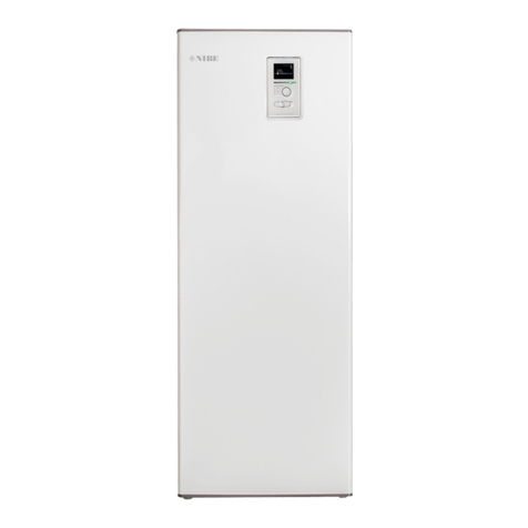
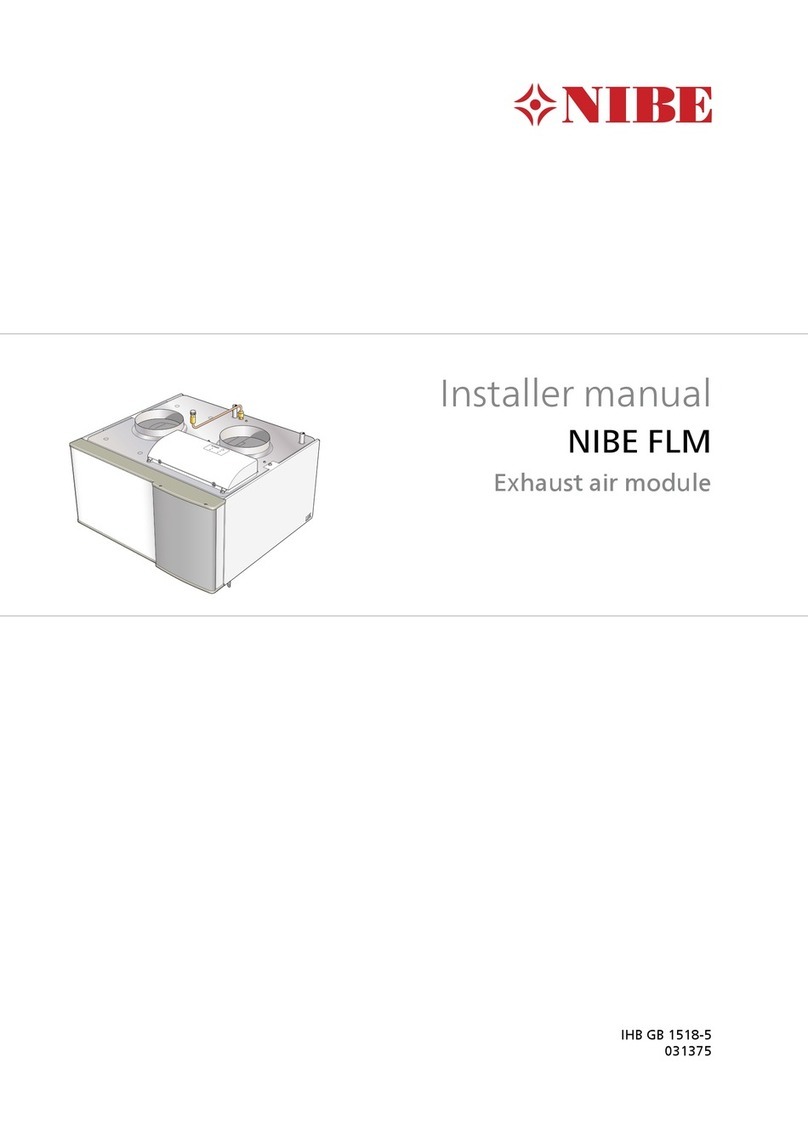
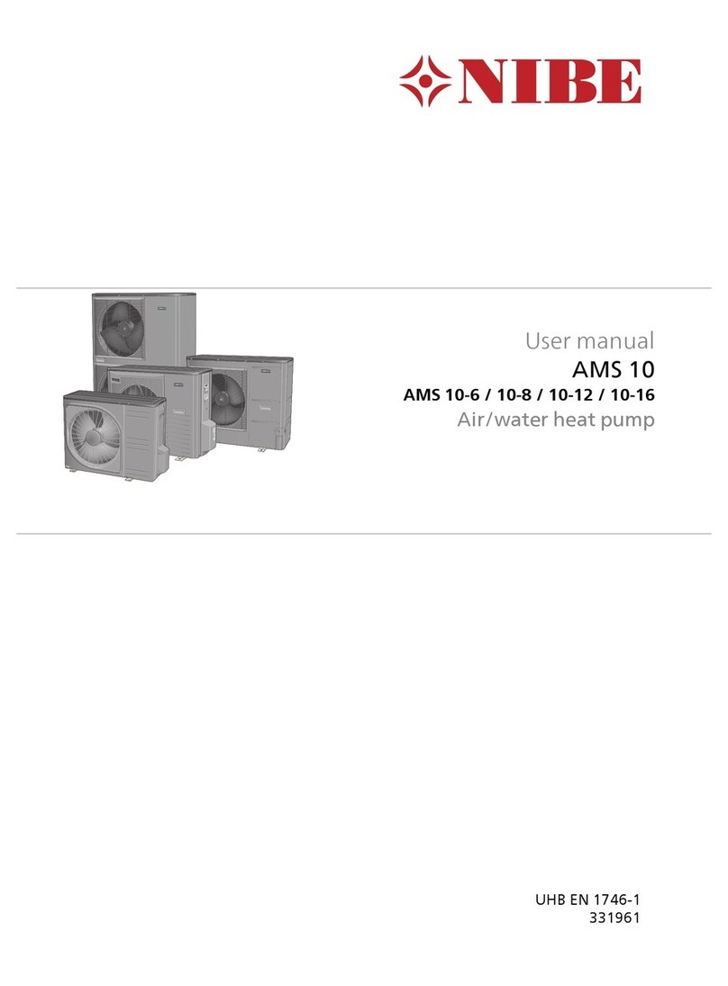
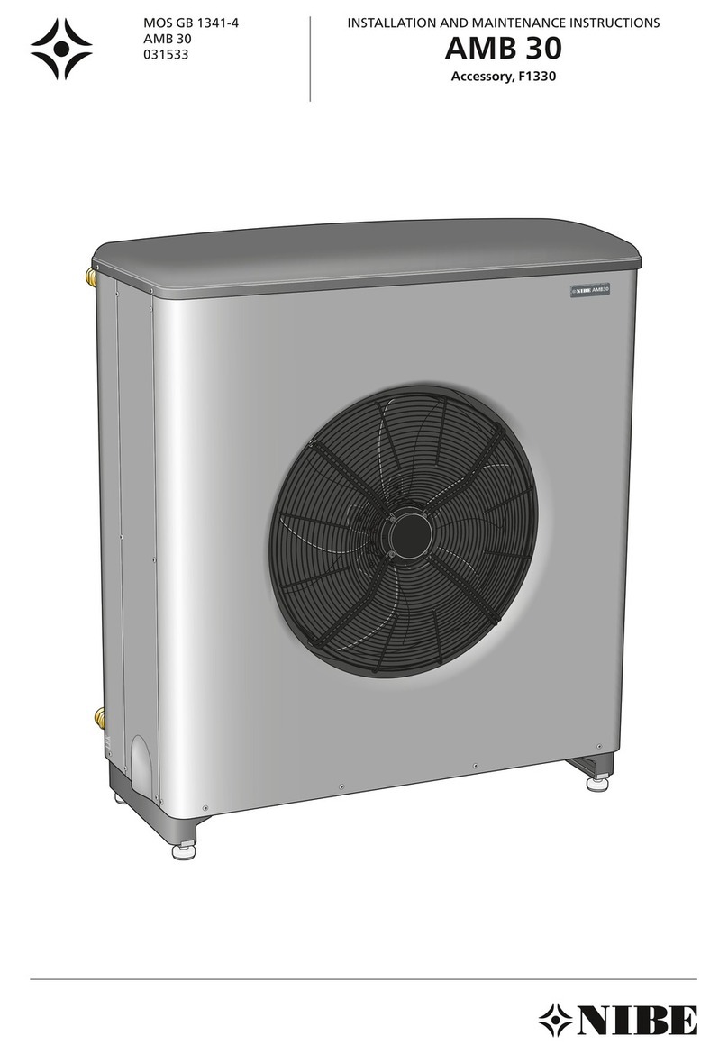
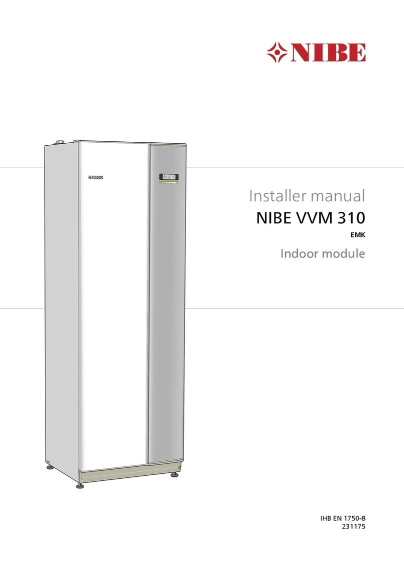
Nibe BA-SVM 10-200 Series User manual

21-01-2019
03-03-2021
Indoor module for air to water split systems
NIBE BA-SVM 10-200
SERVICE MANUAL


3NIBE BA-SVM 10-200
Table of Contents
1 Important information __________ 4
Safety information _______________________ 4
2 Design of the indoor unit _______ 6
BA-SVM10-200 _________________________ 6
3 System description _____________ 8
Principle of operation _____________________ 8
4 Description of functions _______12
Menu Tree ____________________________ 12
Menu 4 - MY SYSTEM ___________________ 14
Menu 5 - SERVICE ______________________ 15
Operating status________________________ 16
Heating ______________________________ 20
Addition _____________________________ 22
5 Current circuit__________________40
Load monitor __________________________ 40
6 Component description _______41
Components___________________________ 41
Sensors______________________________ 45
Electronics____________________________ 46
7 Troubleshooting ________________48
Alarm list_____________________________ 48
Troubleshooting guide____________________ 55
Function check, components _______________ 60
8 Component replacement______61
Main components_______________________ 62
Circuit board and electronics _______________ 69
9 Technical data __________________77
Electrical circuit diagram__________________ 77
Dimensions and pipe connections ___________ 86
Technical data _________________________ 87
10 Item Register _________________89
Item register __________________________ 89

4NIBE BA-SVM 10-200
1 Important information
Safety information
Serial number
Symbols
Marking
BA-SVM 10-200 is CE marked and
has an IP21 protection rating.
The CE mark confirms that NIBE
has ensured that the product
conforms to all applicable regula-
tions specified by the relevant EU
directives. The CE mark is man-
datory for most products sold in
the EU, regardless of where they
are made.
IP21 means that objects with a
diameter greater than or equal to
12.5 mm cannot penetrate and
cause damage and that the prod-
uct is protected against vertically
falling drops of water.
This appliance can be used by
children aged 8 years and above
and persons with reduced phys-
ical, sensory or mental capacity
or lack of experience and knowl-
edge, if they will be supervised
or have received instruction con-
cerning safe use of the appliance,
and if they understand the dan-
ger involved in its use. Children
must not play with the appliance.
Cleaning and basic maintenance
of the appliance must not be car-
ried out by children unsupervised.
The rights to make structural
changes are reserved.
©NIBE 2020
This manual contains installation
and service procedures for imple-
mentation by specialists.
The serial number is located at
the bottom of the identification
plate, on the top cover BA-SVM
10-200 and consists of 14 digits.
CAUTION
This symbol indicates danger
to the appliance or person.
NOTE
This symbol indicates im-
portant information to note
while operating or main-
taining the appliance.
TIP
This symbol indicates tips
that will make it easier to
operate the product. Serial number
BA-SVM
(PF3)
Section 1 | Important information
5NIBE BA-SVM 10-200 Section 1 | Important information
Waste disposal
Leave the disposal of the
packaging to the installer
who installed the product
or to a special waste dis-
posal facility. Improper disposal of the product by
the user may result in administrative
penalties in accordance with the ap-
plicable legislation.
Do not dispose of used products
with normal household waste. It
must be transported to a special
Inspection of the installation
The climate system must be inspected before commissioning. The inspection must be carried out by a suitably
qualified person. In addition, fill in the page for the installation data in the User Manual.
waste disposal facility or to a ven-
dor who provides this type of ser-
vice.

6NIBE BA-SVM 10-200
XL11 XL10 XL4 XL13 XL14
XL3
GP12
AA27
AA8
AA2:X4
AA2:X15
AA2
K2
BT64
XL2
XL1
EP2
QN12
BT12
BF1
CM1 BP4
EB1 BT15
BT63 BT3
BT6
BT7
X10
X0
BT30
FD1
X1
EB1
AA23
FA1
K1A-K3A
FA2
AA3
SF1
X2
AA7
EB2
BT71
XL5 BT25
QN10
Section 2 |
2 Design of the indoor unit
BA-SVM10-200
Design of the indoor unit

7NIBE BA-SVM 10-200
Pipe connections
XL1 Connection, heating medium, supply
XL2 Connection, heating medium, return
XL3 Connection, cold water
XL4 Connection, hot water
XL5 Connection, hot water circulation
XL10 Connection, cooling operation
XL11 Connection, safety assembly,
pressure gauge, vent
XL13 Connection, liquid refrigerant
XL14 Connection, gas refrigerant
HVAC components
CM1 Expansion vessel, closed
QN10 Reversing valve, hot water/climate system
QN12 Reversing valve, heating system/cooling
system
GP12 Circulation pump
EP2 Heat exchanger
Sensors
BP4 Pressure sensor, high pressure
BT3 Temp. sensor, heating medium return
BT6 Temp. sensor, hot water charging
BT7 Temp. sensor, hot water heater top
BT12 Temp. sensor, condenser out
BT15 Temp. sensor, liquid line
BT25 Temp. sensor, heating medium supply
BT63 Temp. sensor, supply heating medium
behind immersion heater
BT64 Temp. sensor, cooling operation system
supply
BT71 Temp. sensor, heating medium return
Electrical components
X0 Terminal block- 400V~
X1 Terminal block- 230V~
X2 Terminal block- 230V~
X10 Terminal block- 230V~
AA2:X4 Terminal block- low voltage
AA2: X15 Terminal block- low voltage
K1A-K3A Contactor for immersion heater
K2 Alarm relay
BT30 Standby mode thermostat
AA2 Main board
AA3 Sensor board
AA23 Communication board
AA7 Relay board
AA8 Titanium anode board
(Does not apply to BA-SVM 10-200 R)
AA27 Relay board
FD1 Thermal circuit breaker
FA1 Miniature circuit breaker (protecting the
indoor unit)
FA2 Miniature circuit breaker (protecting the
outdoor unit)
EB1 Electric additional heat
Miscellaneous
BF1 Energy meter
(Does apply to BA-SVM 10-200 E EM only)
SF1 Controller switch
EB2 Hot water tank
Section 2 | Design of the indoor unit

8NIBE BA-SVM 10-200
P
P
AA4
XL10
BT63
BT25
XL1
QN10
XL2
XL3
BT71
XL5
XL4
EB1
QN12
BT64
XL11
XL19 XL18
GP12
BT12
XL14
EP2
BT15
XL13
CM1
HS1
BP4
BT3
BT7
BT6
FL1
3 System description
Principle of operation
Pipe connections
XL1 Connection, heating medium, supply
XL2 Connection, heating medium, return
XL3 Connection, cold water
XL4 Connection, hot water
XL5 Connection, hot water circulation
XL10 Connection, cooling operation
XL11 Connection, safety assembly,
pressure gauge
XL13 Connection, liquid refrigerant
XL14 Connection, gas refrigerant
XL 18 Connection, return to add. heat source
XL 19 Connection, supply from add. heat source
FL1 Safety group
HVAC components
CM1 Expansion vessel, closed
QN10 Reversing valve, hot water/climate system
QN12 Reversing valve, heating system/cooling
system
Sensors etc.
BP4 Pressure sensor, high pressure
BT3 Temp. sensor, heating medium return
BT6 Temp. sensor, hot water charging
BT7 Temp. sensor, hot water heater top
BT12 Temp. sensor, condenser out
BT15 Temp. sensor, liquid line
BT25 Temp. sensor, heating medium supply
BT63 Temp. sensor, supply heating medium
behind immersion heater
BT64 Temp. sensor, cooling operation system
supply
BT71 Temp. sensor, heating medium return
EB1 Electric additional heat
AA4 Display
Section 3 | System description
GP12 Circulation pump
EP2 Heat exchanger
HS1 Drying filter

9NIBE BA-SVM 10-200
XL10
XL14 XL1
XL13 XL2
XL3
XL5
XL4
-EB101
-BT1
BA-SVM 10-200
-GP11
P
XL18XL19
HS1 -BP4
-BT15
-BT12
-BT3
-GP12 -BT25
-QN12 -BT63
-BT71
-QN10
-BT7
-BT6
P
EQ-BT25/BT64
Shut-off valve
Non-return valve
Shunt valve
Safety valve
Temperature sensor
Expansion vessel
Pressure gauge
Automatic air vent
KEY
Circulation pump
Electric heating
Cooling system filter
Compressor
Plate heat exchanger
Cooling operation
Heating system
(radiators)
Central heating system
(under floor heating sys-
tems)
Domestic hot water
Relief valve
Additional heat source
Buffer vessel
Fan coil
-BT64
A dotted line indicates
that you need to transfer
the temperature sensor
Basic diagram
Section 3 | System description

10 NIBE BA-SVM 10-200
XL10
XL1
XL2
-EB101
-BT1
BA-SVM 10-200
-GP11
P
XL18XL19
HS1 -BP4
-BT15
-BT3
-GP12 -BT25
-QN12 -BT63
-BT71
-QN10
-BT7
-BT6
P
-BT2
-BT3
-QN11
-GP20
AA25
EQ-BT25/BT64
-BT12
XL14
XL13
XL3
XL5
XL4
XL10
XL1
XL2
-EB101
-BT1
-BT64
BA-SVM 10-200
-GP13
P
XL18XL19
HS1 -BP4
-BT15
-BT12
-BT3
-GP12 -BT25
-QN12 -BT63
-BT71
-QN10
-BT7
-BT6
P
EQ-BT25/BT64
-GP11
XL14
XL13
XL3
XL5
XL4
Diagram of 2-pipe cooling operation
Diagram of 4-pipe cooling operation
Section 3 | System description

11NIBE BA-SVM 10-200
XL10
XL1
XL2
-EB101
-BT1
BA-SVM 10-200
-GP11
P
XL18XL19
HS1 -BP4
-BT15
-BT12
-BT3
-GP12 -BT25
-QN12 -BT63
-BT71
-QN10
-BT7
-BT6
P
EQ-BT25/BT64
XL14
XL13
XL3
XL5
XL4
Diagram showing connection of an additional heat source
NOTE
The maximum power of the additional heat source can-
not exceed 15kW.
Section 3 | System description

12 NIBE BA-SVM 10-200
4 Description of functions
Menu 1- INDOOR CLIMATE
Menu Tree
1-INDOOR CLIMATE 1.1 temperature 1.1.1- heating
1.1.2- cooling
1.2- ventilation 1
1.3- scheduling 1.3.1- heating
1.3.2- cooling
1.3.3- ventilation 1
1.9- advanced 1.9.1- curve 1.9.1.1- heating curve
1.9.1.2- cooling curve
1.9.2- external adjustment
1.9.3- min. flow line temp. 1.9.3.1- heating
1.9.3.2- cooling
1.9.4- room sensor settings
1.9.5- cooling settings
1.9.6- fan return time1
1.9.7- own curve 1.9.7.1- heating
1.9.7.2- cooling
1.9.8- point offset
1The ERS additional equipment is necessary.
Section 4 | Description of functions

13NIBE BA-SVM 10-200
Menu 2- HOT WATER
Menu 3- INFO
3- INFO 3.1- service info
3.2- compressor info
3.3- add. heat info
3.4- alarm log
3.5- indoor temp. log
2The AXC 30 additional equipment is necessary.
2- HOT WATER 2.1- temporary lux
2.2- comfort mode
2.3- scheduling
2.9- advanced 2.9.1- periodic increase
2.9.2- hot water recirc.2
Section 4 | Description of functions

14 NIBE BA-SVM 10-200
Menu 4- MY SYSTEM
4- MY SYSTEM 4.1- plus functions 4.1.1- pool 3
4.1.2- pool 2 3
4.1.3- internet 4.1.3.1- Uplink
4.1.3.8- tcp/ip settings
4.1.3.9- proxy settings
4.1.4- sms 4
4.1.5- SG Ready
4.1.6- smart price adapt.
4.1.7- smart home
4.1.8- smart energy source 4.1.8.1- settings
4.1.8.2- set. price
4.1.8.3- CO2 impact
4.1.8.4 - tariff periods, electricity
4.1.8.6 - tariff per, ext. shunt add
4.1.8.7- tariff per, ext. step add
4.1.8.8- tariff periods
4.1.10- solar electricity 5
4.2- op. mode
4.3- my icons
4.4- time & date
4.6- language
4.7- holiday setting
4.9- advanced 4.9.1- op. prioritisation
4.9.2- auto mode setting
4.9.3- degree minute setting
4.9.4- factory setting user
4.9.5- schedule blocking
4.9.6- schedule silent mode
3The POOL 40 additional equipment is necessary.
4The SMS 40 additional equipment is necessary.
5The EME 20 additional equipment is necessary.
Section 4 | Description of functions

15NIBE BA-SVM 10-200
Menu 5- SERVICE
5- SERVICE 5.1- operating settings 5.1.1- hot water settings 6
5.1.2 - max flow line temperature
5.1.3- max diff flow line temp.
5.1.4- alarm actions
5.1.5- fan sp. exhaust air 7
5.1.6- fan sp. supply air 7
5.1.12- addition
5.1.14- flow set. climate system
5.1.22- heat pump testing
5.1.23- compressor curve
5.1.25- time filter alarm
5.2 - system settings 5.2.2- installed slaves
5.2.3- docking
5.2.4- accessories
5.3- accessory settings 5.3.2 - shunt controlled add. heat
5.3.3- extra climate system 8
5.3.4- solar heating 9
5.3.6- step controlled add. heat
5.3.8- hot water comfort 6
5.3.11- modbus 10
5.3.12- exhaust/supply air module 7
5.3.14- F13511
5.3.15 - GBM communications module12
5.3.16- humidity sensor 13
5.3.21- flow sensor / energy meter 14
5.4- soft in/outputs
5.5- factory setting service
5.6- forced control
5.7- start guide
5.8- quick start
5.9- floor drying function
5.10- change log
5.11- slave settings 5.11.1- EB101 5.11.1.1- heat pump
5.11.1.2- charge pump (GP12)
5.11.2- EB102
5.11.3- EB103
5.11.4- EB104
5.11.5- EB105
5.11.6- EB106
5.11.7- EB107
5.11.8- EB108
5.12- country
6The AXC 30 additional equipment is necessary.
7The ERS additional equipment is necessary.
8The ECS additional equipment is necessary.
9The SOLAR 40 additional equipment is necessary.
10 The MODBUS 40 additional equipment is necessary.
11 The F135 additional equipment is necessary.
12 The OPT 10 additional equipment is necessary.
13 The HTS 40 additional equipment is necessary.
14 The EMK 300 additional equipment is necessary.
Section 4 | Description of functions

16 NIBE BA-SVM 10-200
Operating status
General
There are three operating modes available: Auto,
Manual and Add. heat only.
Operating
mode
(menu 4.2)
Selectable
functions Remarks
auto auto All operating
modes permitted
manual heating,
addition,
cooling
cooling only dis-
played if selected in
menu 5.2.
Cooling and heating
can be selected
simultaneously if:
• a room sensor is
installed and ac-
tivated
or
• 4-pipe cooling
system used.
add. heat
only
heating compressor
blocked
If addition is blocked it is permitted when:
• hot water lux, temporary or continuous.
• periodic hot water increase.
• auxiliary operation if the compressor is blocked.
• anti-freeze.
• cooling operation.
Blocking of additional heat regards heat production
but can to some degree also affect hot water pro-
duction.
Hot water production can be blocked in the schedule.
In Auto operating mode the control selects the oper-
ating mode based on the following parameters. The
temperatures are average temperature during the
time it is selected in “filter time”.
Menu Name Factory
setting
Remarks
4.9.2 Stop
addition
+5 °C Icons in the main
menu and in
menu 4.2 are dis-
played when addi-
tion is blocked.
Stop
heating
+17 °C Icons appear in
menu 4.2 when
heating is blocked.
Filter
time
24 hrs Time for average
temperature cal-
culation
Auxiliary operation
“Auxiliary operation” is a type of emergency mode
that can be selected manually when the alarm has
occurred.
This means that the heat pump produces heat and/or
hot water despite there being some kind of problem.
This can mean that the heat pump’s compressor is
not running. In this case the immersion heater pro-
duces heat and/or hot water.
Status lamp lights red in the event of a deployed aux-
iliary operation.
Section 4 | Description of functions

17NIBE BA-SVM 10-200
Anti-freeze climate system BA-SVM 10-200
If heating is actively shut-off and it becomes colder outdoors, heating is activated to prevent the heating system
from freezing.
If heating is blocked and the outdoor temperature (BT1) drops below +3°C, the anti-freeze function activates.
• Heating medium pump GP12 starts and the heating calculation with min supply line as set point value.
• Additional heat is permitted, even if another function has blocked it, but the compressor will remain blocked.
The alarm and load monitor can block/restrict the additional heat however.
• There is no anti-freeze for pool.
If the anti-freeze function is active and the outdoor temperature (BT1) exceeds +3.5°C, the anti-freeze function
deactivates.
Circulation pumps connected to accessory cards are active.
Anti-freezing outdoor unit
Frysskydd
av utedel
Givarfel på utetemp (1:a
hand OU_BT28
2:a hand EB100 - BT1) el.
OU_BT3 el. OU_BT12
Frysskydd
aktivt
Utedel
saknas
Tid i sek som GP12 stått
stilla sedan den senast
gick > f(utetemp)*
BT12 < 10
eller
BT3 < 10
BT12 > 40
och
BT3 > 40
BT12 > 20
och
BT3 > 20
Pump aktiv
> 1 min
Aktivera
frysskydd
Inaktivera
frysskydd
Avaktivera
frysskydd
Markera frysskydd
aktivt
Ja Nej
NejNej
Nej
Nej
Nej
Nej
Nej
Nej
Nej
Nej
Ja
Ja
Ja
Ja
Ja
Ja
Ja
Ja
Ja Ja
Frysskydd
inaktivt
Frysskydd
inaktivt
Frysskydd
aktivt
BT28 < 2°C
Frysskydd
aktivt
Frysskydd
aktivt
Frysskydd
aktivt
* f är en rät linje som anger tid mellan
pumpdrift som funktion av BT28.
f(utetemp)=90*utetemp+3000 (ute-
temp i °C).
Ex)
utetemp = 0°C => 3000 s (50 min)
utetemp = -30°C => 300 s (5 min)
utetemp = +10°C => 3900 s (65 min)
VVM 500 / 310 / 320
SMO 20/ SMO 40
Yes No
Yes
Yes
Yes
Yes
Yes
Yes
Yes
Yes
Yes
No
No
No
No
No
No
No
No
No
No
Anti-freeze
of outdoor unit
Anti-freeze
active
Activate
anti-freeze
Anti-freeze
active
Deactivate
anti-freeze
Anti-freeze
active
Anti-freeze
active
Anti-freeze
not active
BT28 <2°C
Sensor fault on outdoor
temp
(1st OU_BT28
2nd EB100 -BT1) el.
OU_BT3 el. OU_BT12
Outdoor unit
missing
Time in seconds that
GP12 has been
stationary since it last
ran > f(outdoor temp)*
BT12 <10
or
BT3 <10
Mark anti-freeze
active
BT12 >40
and
BT3 >40
Pump active
>1min
BT12 >20
and
BT3 >20
Deactivate
anti-freeze
Anti-freeze
not active
Anti-freeze
active
* sastraight line that indicates the
time between pump operations as a
function of BT28.
f(outdoor temp)=90*outdoor
temp+3000 (outdoor temp in °C).
E.g.
outdoor temp=0°C=> 3000 s (50
min)
outdoor temp=-30°C=> 300 s (5
min)
outdoor temp=+10°C=> 3900 s (65
min)
BA-SVM 10-200
Section 4 | Description of functions

18 NIBE BA-SVM 10-200
Emergency mode
Emergency mode is selected with the control switch,
and is indicated by a yellow lamp.
Internal circulation pump GP12 runs at full speed and
GP10 is external. Reversing valve (QN10) is open to-
wards the heating system.
The immersion heater power is set with the dip-
switch on the immersion heater card (AA1). The max
flow temperature can be set to between 35 and 45°C
on the emergency mode thermostat (FD1) .
External circulation pumps do not run.
Factory setting:
Immersion heater output 6 kW (Dipswitch setting,
immersion heater card (AA1): 101010)
Emergency mode thermostat set to 35 °C.
Add. heat only
To run the system without heat pump connected, its
pipe ends must be connected together to ensure cir-
culation in the charge circuit. Also check that there is
antifreeze.
Heat pump EB10X must be deactivated in menu 5.2.2
to prevent communication alarm.
Operating mode must be set to only additional heat.
Sensor calibration
Sensors are calibrated to increase accuracy of control
and energy measurement. Calibration occurs at start-
up and every 3 months. If BA-SVM 10-200 restarts
calibration starts again and the correction value is = 0.
In BA-SVM 10-200, EB 101-BT3 is calibrated to EB101-
BT12 and GP12 runs, gives info alarm. 354. There-
after, with the calibrated and adjusted EB101-BT3,
BT63 is adjusted, gives info alarm 355.
Calibration sequence:
• When neither compressor nor internal immersion
heater work towards any demand, GP12 runs at
maximum permitted speed, all reversing valves
must be set to heating.
• When GP12 has run for 6 minutes and the com-
pressor as well as the internal immersion heater
have not been active, the average value of EB101-
BT3 and EB101-BT12 are taken and calibrated
against each other during the last minute.
• Then the two average values are compared and
the two sensors (EB101-BT3 and EB101-BT12) are
adjusted equally, the BT63 is adjusted according
to the calibrated and adjusted EB101-BT3.
• If calibration fails 3 times, info alarm 354 and BA-SVM
10-200 cease calibration until EB101 is restarted.
Reasons to cancel or not start calibration:
• Forced control active
• Demand other than OFF on compressor
• Start guide active
• Flow guide active
• Phase detection active
• Sensor fault on supply/return sensor
• Compressor active
• Electric additional heat active
• Alarm or info alarm active
• Heating not permitted
• Cooling permitted as well as two-pipe cooling active
Hot water
General
Three hot water temperatures can be selected. Econ-
omy, Normal and Lux.
The demand for, charging and energy type is based on
the settings for hot water comfort. Hot water may only
be produced by compressor except in cases where:
• DM less than Start_DM-Start_DM_additional heat
and Start_DM_additional heat is greater than 0
• DM less than Start_DM+Start_DM_additional
heat and Start_DM_additional heat is less than 0
Priority sequence
Hot water is produced according to the following
function/setting:
1. Selecting hot water production. (Yes/No.)
2. Alarms are handled in relation to the selected
alarm action.
3. Temporary lux.
4. AUX input ”temporary lux”.
5. Holiday setting.
6. Periodic increase.
7. Scheduling hot water.
8. Normally set comfort mode.
Hot water capacity
The main menu displays a water drop with 3 fields to
indicate how much hot water is available.
Average temp Number of fields
Above 52 °C 3
Between 46 and 52 °C 2
Between 40 and 46 °C 1
Below 40 °C 0
Section 4 | Description of functions

19NIBE BA-SVM 10-200
The capacity is calculated on the average tempera-
ture of BT6 and BT7 if BT7 is connected, otherwise
the values apply from BT6.
Hot water production Economy
Hot water demand occurs when:
• the temperature falls below the start temp on
BT6.
Hot water demand ceases when one of the following
conditions is filled:
• the temperature is above the stop temp on BT6.
• Condenser supply line: BT12 ≥ max condenser
out -1K. (different depending on which external
part is installed).
• Condenser return line: BT3 ≥ max condenser in
- 1K. (different depending on which outdoor unit
is installed).
Default values
Menu Start temp.
economy
Stop temp.
economy
5.1.1 39 °C 43 °C
Limited so that the difference between start and stop
temperature is at least 3 K.
Hot water production Normal
TIP
Selection of comfort mode (economy, normal
and lux) made in menu 2.2.
TIP
Selection of comfort mode (economy, normal
and lux) made in menu 2.2.
TIP
Selection of comfort mode (economy, normal
and lux) made in menu 2.2.
Hot water demand occurs when:
• the temperature falls below the start temp on
BT6. Hot water demand ceases when one of the
following conditions is filled:
• the temperature is above the stop temp on BT6.
• Condenser supply line: BT12 ≥ max condenser
out -1K. (different depending on which external
part is installed).
• Condenser return line: BT3 ≥ max condenser in
- 1K. (different depending on which outdoor unit
is installed).
Default values
Menu start temp.
normal
stop temp.
normal
5.1.1 42 °C 46 °C
Limited so that the difference between start and stop
temperature is at least 3 K.
Hot water production Lux
Hot water is produced by the compressor until the ex-
ternal part’s maximum supply temperature (BT12) or
maximum return temperature (BT3) is reached minus
one degree and thereafter by the set additional heat.
Hot water demand occurs when:
• the temperature falls below the start temp on BT6.
Hot water demand stops when:
• the compressor cannot produce as above and the
internal additional heat is blocked.
• the temperature is above the stop temp on BT6.
• the compressor can no longer produce and the
internal additional heat is defined as 0 kW and
there is no external additional heat.
Default values
Menu Start temp.
economy
Stop temp.
economy
5.1.1 45 °C 49 °C
Limited so that the difference between start and stop
temperature is at least 3 K.
Hot water production below the balance point
Produces heating and hot water alternately.
Hot water production with internal immer-
sion heater
When hot water production only occurs with the im-
mersion heater, the max permitted electrical output
is used according to menu 5.1.12.
Temporary lux
Temporary lux can be selected in menu 2.1. Selecta-
ble modes 3 h, 6 h, 12 h and Off.
No increase occurs if comfort mode Lux is selected.
Section 4 | Description of functions

20 NIBE BA-SVM 10-200
Heating
Heating
Heat produced with selected outdoor unit.
Heating can also be created with one of the following:
• Internal electric additional heat before. QN10
• External additional heat
Continuous circulation of heat in the heating system
occurs:
• GP12 circulates the heating system during heat-
ing operation and waiting mode.
Desired supply temperature calculated as function of
filtered outdoor temperature with heat curve and any
offset.
Degree minutes
The heating requirement is calculated every minute
using the following formula (DM = Degree minutes):
New DM = Previous DM + (actual value- set point value)
Actual value is the temperature on BT2.
Actual value is the temperature on BT25. If not avail-
able, BT2 is used.
Set point value is the calculated flow temperature.
Degree minutes (DM):
• DM is calculated every minute.
• DM is calculated in steps of 0.1 and displayed in
whole units.
• Manual change of DM occurs in units of ten,
menu 4.9.3.
• At start-up DM is always 0.
• When heating is not permitted DM is locked on 0.
• Highest DM value is +100.
• Lowest DM value is the value of the last addi-
tional heat step connection plus the difference
between additional heat steps.
Menu Name Factory setting
4.9.3 Start comp -60
Start addition 400
Diff between
additional heat step
30
Forced control of degree minutes
Forced control is used to stop the compressor and
auxiliary heater when the actual value is too high in
relation to the set point value.
NOTE
Forced control is not active during and 5 minutes after
a start or a shift from one demand to another.
Menu Name Factory
setting
Remarks
5.1.3 Max diff. 10 °C Sets DM to:
+1
Max diff.
additional
heat
7 °C Sets DM to:
Start addi-
tional heat
+ diff
between
additional
heat step +1
Heating curve
Curve coefficient and offset are used for setting of
correct set point value.
15 heat curves can be used.
Menu Name Factory setting
1.9.1 Curve coefficient 7
Curve offset 0
Point offset
With point offset, the heating curve can be changed
at a specific outdoor temperature. The change starts
5 °C below and stops 5 °C above the set outdoor
temperature point.
Menu Name Factory setting
1.9.8 Outdoor tempera-
ture point
0 °C
Change in curve 0 °C
Own curve
In own curve the desired flow temperature is select-
ed at fixed outdoor temperatures from-30 to +30 °C .
Menu Name Factory setting
1.9.7 Flow.temp-30 C 45 °C
Flow.temp-20 C 40 °C
Flow.temp-10 C 35 °C
Flow.temp 0 C 32 °C
Flow.temp 10 C 26 °C
Flow.temp 20 C 15 °C
Flow.temp 30 C 15 °C
Section 4 | Description of functions
Other manuals for BA-SVM 10-200 Series
1
Table of contents
Other Nibe Air Conditioner manuals
Popular Air Conditioner manuals by other brands

Samsung
Samsung AW Series Manual de instrucciones

Mitsubishi Electric
Mitsubishi Electric PQRY-P200YEM-A Service handbook

Electrolux
Electrolux FAC124P1A installation instructions

LG
LG VR122HL NB1 owner's manual

INVENTOR
INVENTOR LV6LI-12WiFiR installation manual

Mitsubishi
Mitsubishi PCFY-P VKM-E installation manual