Nibe DVC 10-50 User manual

USER’S MANUAL
Heat recovery single-room
reversible ventilator
DVC 10-50
DVC 10-50L
DVC 10-50W
DVC 10-50WL

www.nibe.com
2
DVC 10-50 (W)
Read the user’s manual carefully prior to installing and operating the unit.
Fulfil the user’s manual requirements as well as the provisions of all the applicable local and national construction, electrical and technical norms and
standards.
The warnings contained in the user’s manual must be considered most seriously since they contain vital personal safety information.
Failure to follow the rules and safety precautions noted in this user’s manual may result in an injury or unit damage.
After a careful reading of the manual, keep it for the entire service life of the unit.
While transferring the unit control the User’s manual must be turned over to the receiving operator.
Symbol legend:
The user’s manual consisting of the technical details, operating instructions and technical specification applies to the installation and mounting of the single-
room reversible ventilator with energy regeneration NIBE DVC 10 (hereinafter «the unit» as mentioned in the «Safety Requirements» and «Manufacturer’s
Warranty» sections as well as in warnings and information blocks).
CONTENTS
SAFETY REQUIREMENTS
Safety requirements....................................................................................................................................2
Purpose...............................................................................................................................................................4
Delivery set.......................................................................................................................................................4
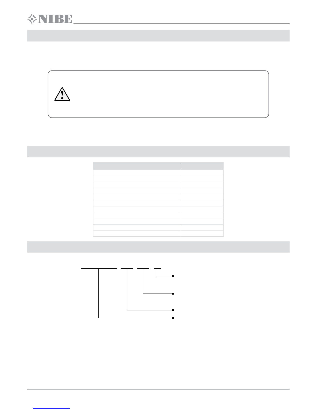
Designation key.............................................................................................................................................4
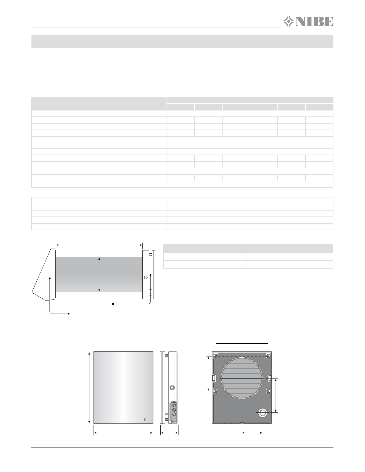
Technical data.................................................................................................................................................5
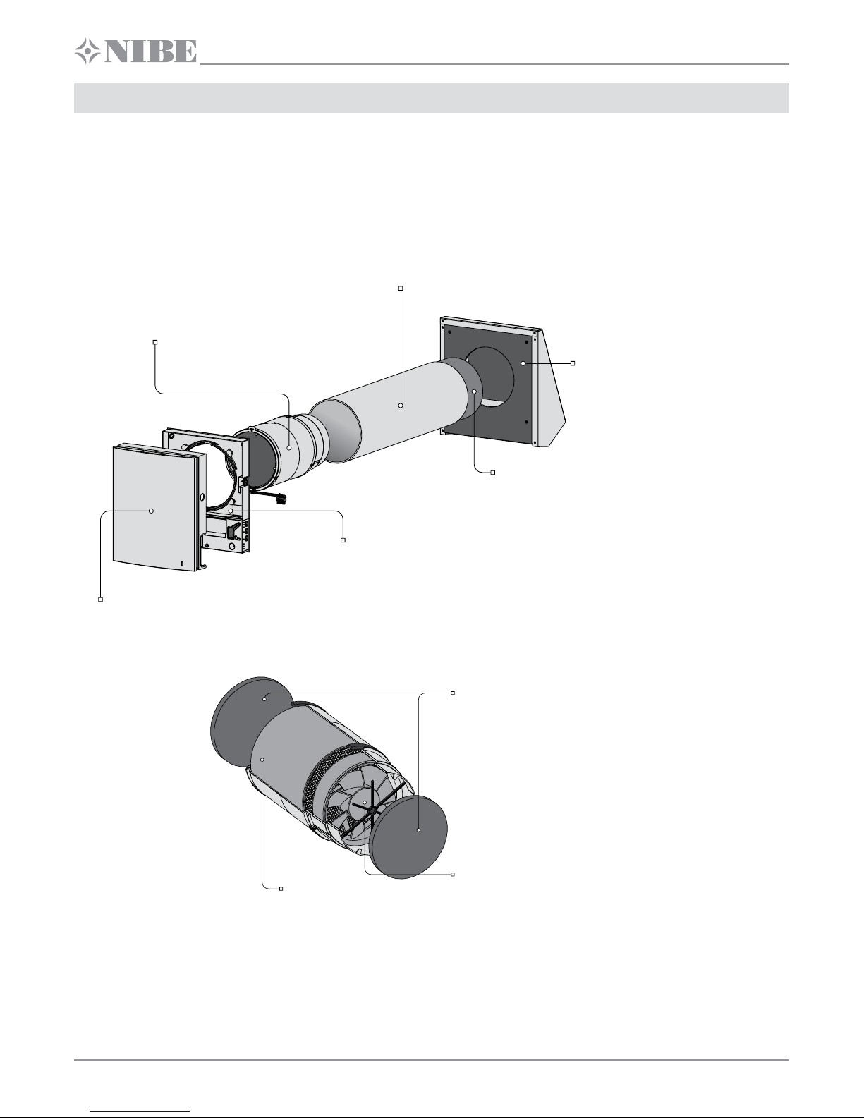
Design and functioning ...........................................................................................................................6
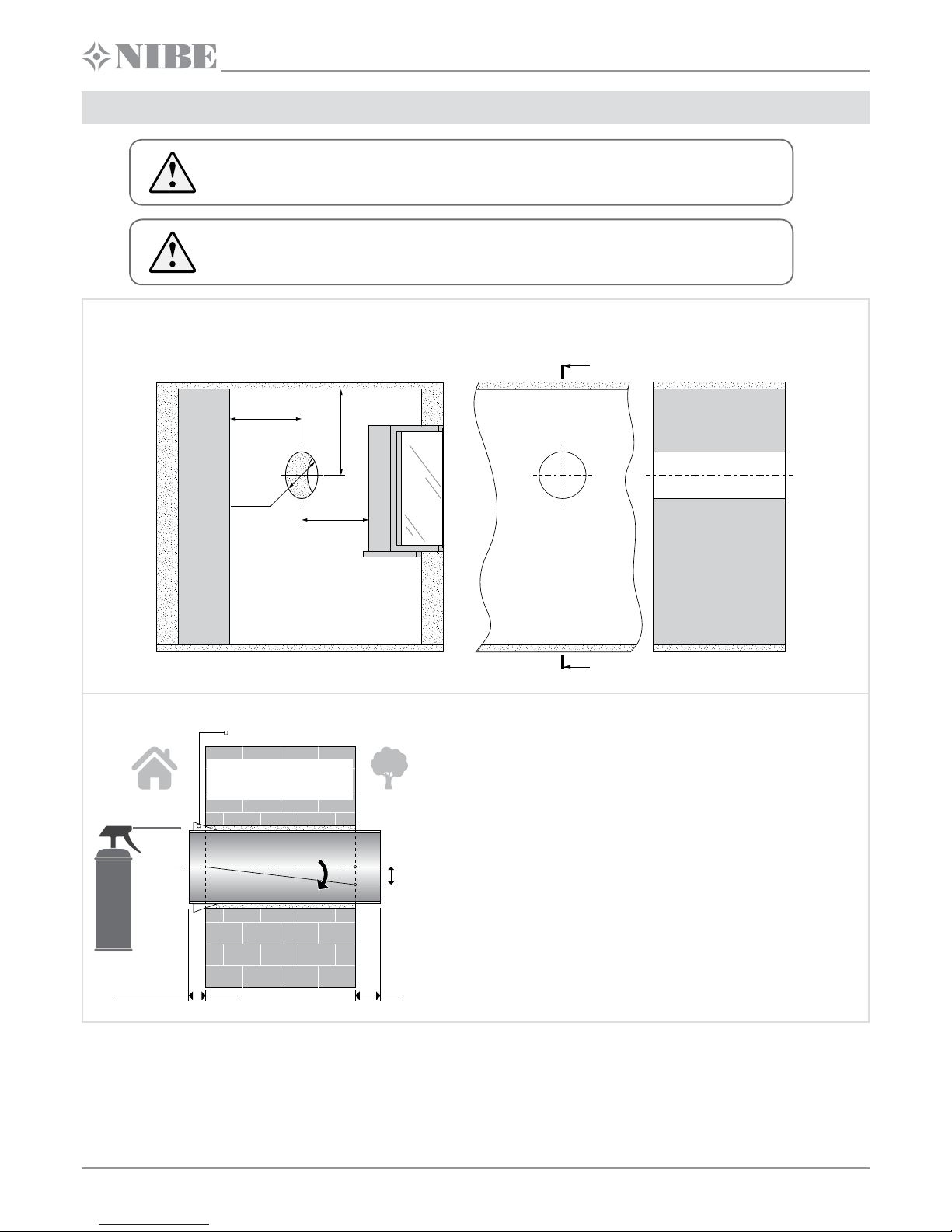
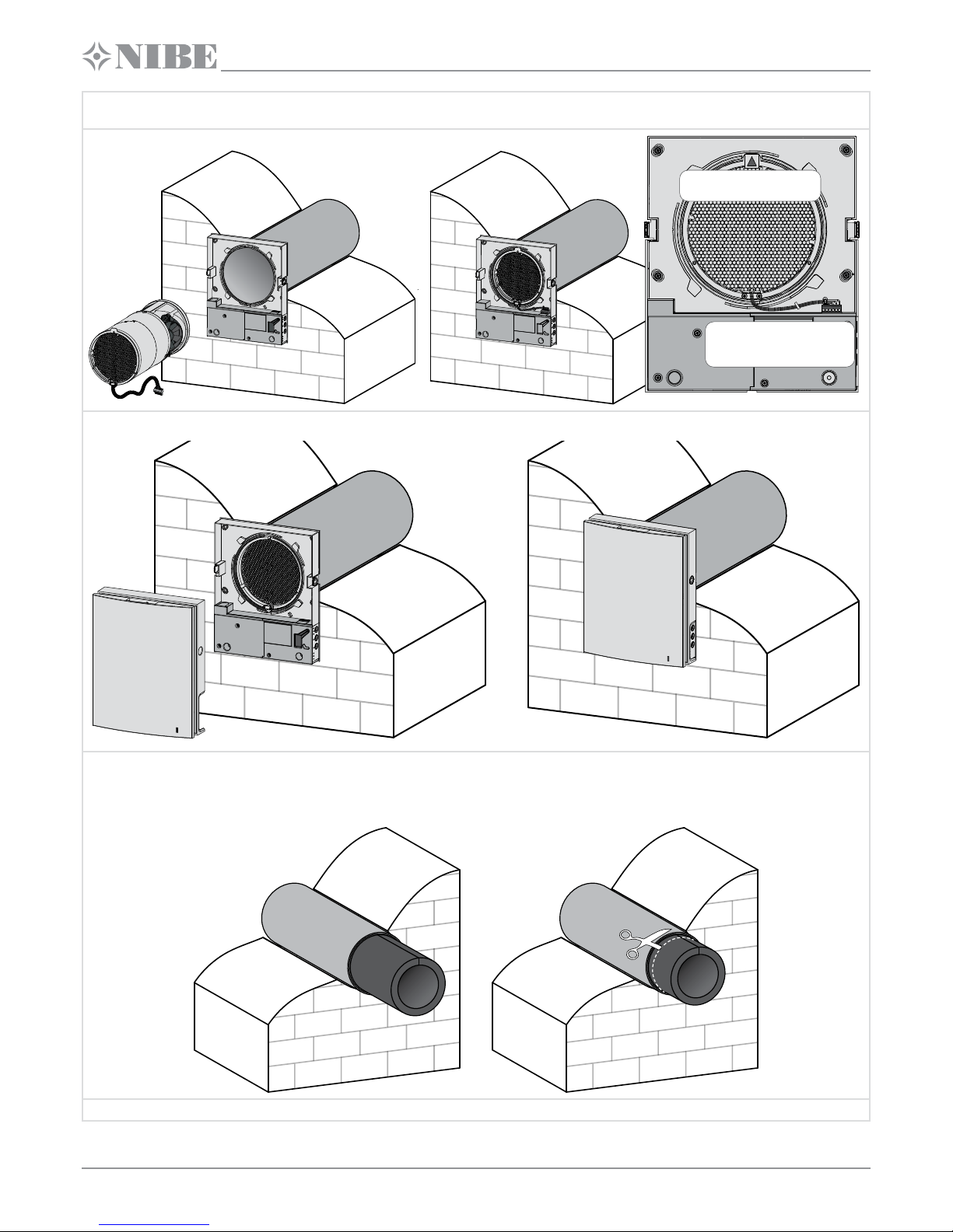
Mounting and set-up.................................................................................................................................8
Connection to power supply and control.................................................................................11
Maintenance.................................................................................................................................................28
Troubleshooting.........................................................................................................................................30
Storage and transportation regulations ....................................................................................30
Manufacturer’s warranty.......................................................................................................................31
Acceptance certificate ...........................................................................................................................32
Seller information......................................................................................................................................32
Installation certificate..............................................................................................................................32
Warranty card...............................................................................................................................................32
WARNING!
DO NOT!
UNIT MOUNTING AND OPERATION SAFETY PRECAUTIONS
• Disconnect the unit from power mains prior to
any installation operations. • Unpack the unit with care.
• Do not lay the power cable of the unit in close
proximity to heating equipment.
• While installing the unit follow the safety
regulations specific to the use of electric tools.
• Do not use damaged equipment or cables
when connecting the unit to power mains.
• Do not operate the unit outside the
temperature range stated in the user's manual.
• Do not operate the unit in aggressive or
explosive environments.

www.nibe.com
3
• Do not touch the unit controls with wet hands.
• Do not carry out the installation and
maintenance operations with wet hands.
• Do not wash the unit with water.
• Protect the electric parts of the unit against
ingress of water.
UNIT MOUNTING AND OPERATION SAFETY PRECAUTIONS
• Do not allow children to operate the unit. • Disconnect the unit from power mains prior to
any technical maintenance.
• Do not store any explosive or highly flammable
substances in close proximity to the unit.
• When the unit generates unusual sounds, odour
or emits smoke disconnect it from power supply
and contact the Seller.
• Do not open the unit during operation. • Do not direct the air flow produced by the unit
towards open flame or ignition sources.
• Do not block the air duct when the unit is
switched on.
• In case of continuous operation of the unit
periodically check the security of mounting.
• Do not sit on the unit and avoid placing foreign
objects on it. • Use the unit only for its intended purpose.
THE PRODUCT MUST BE COLLECTED SEPARATELY AT THE END OF SERVICE LIFE.
DO NOT DISPOSE OF AS UNSORTED MUNICIPAL WASTE.

www.nibe.com
4
DVC 10-50 (W)
The ventilator is designed to ensure continuous mechanical air exchange in houses, offices, hotels, cafes, conference halls and other utility and public
spaces. The ventilator is equipped with a ceramic regenerator that enables supply of fresh filtered air heated by means of extract air heat energy
regeneration.
The unit is designed for through-the-wall mounting.
PURPOSE
The unit is rated for continuous operation.
Transported air must not contain any flammable or explosive mixtures, evaporation of chemicals, sticky substances, fibrous materials, coarse dust, soot
and oil particles or environments favourable for the formation of hazardous substances (toxic substances, dust, pathogenic germs).
THE UNIT MAY NOT BE OPERATED BY CHILDREN OR PERSONS WITH REDUCED PHYSICAL,
MENTAL OR SENSORY CAPACITIES, OR LACKING THE APPROPRIATETRAINING.
THE UNIT MUST BE INSTALLED AND CONNECTED ONLY BY PROPERLY QUALIFIED PERSONNEL
AFTER THE APPROPRIATE BRIEFING.
THE CHOICE OF UNIT INSTALLATION LOCATION MUST PREVENT UNAUTHORIZED ACCESS BY
UNATTENDED CHILDREN.
DELIVERY SET
Name Quantity
Indoor unit 1 item
Air duct 1 item
Sound absorbing material 1 item
Cartridge 1 item
Outer ventilation hood 1 item
Remote control 1 item
Cardboard template 1 item
Fastening kit 2 boxes
User's manual 1 item
Outer hood installation instruction 1 item
Packing box 1item
DESIGNATION KEY
DVC 10-50 W L
Air duct length
_: 500 mm
L: 700 mm
Rated air capacity [m3/h]
Automation type
_: cable connection of the units
W: wireless connection of the units
Ventilator series

www.nibe.com
5
TECHNICAL DATA
The unit is rated for indoor application with the ambient temperature ranging from -30 °C up to +50 °C and relative humidity up to 97 %.
The unit is rated as a class II electric appliance.
Ingress Protection (IP) rating from solid objects and liquids IP24.
The unit design is regularly improved, so some models may slightly differ from those ones described in this manual.
TECHNICAL DATA
Speed DVC 10-50 (L) DVC 10-50W (L)
I II III I II III
Supply voltage, 50-60 Hz [V] 1~ 100 - 240 1~ 100 - 240
Power consumption [W] 3.61 4.15 5.2 4.45 5.08 7.06
Current consumption [A] 0.025 0.030 0.039 0.035 0.040 0.059
Air capacity [m3/h] 15 30 50 15 30 50
Filters G3 (MERV 7);
F8 (MERV 13) option
G3 (MERV 7);
F8 (MERV 13) option
Transported air temperature [˚C] (˚F) from -30 (-22) to 50 (122)
Noise level, 1 m [dB(A)] (Sones) 20 27 30 20 27 30
Noise level, 3 m [dB(A)] (Sones) 11 18 21 11 18 21
Noise level attenuation [dB(A)] (Sones) 42 42
Heat recovery efficiency [%] 97 90 82 97 90 82
Ingress Protection (IP) IP24 IP24
WIFI TECHNICAL DATA APPLICABLE FOR DVC 1050WL ONLY
Standard: IEEE 802.11 b/g/n
Frequency band [GHz] 2.4
Transmission power [mW] (dBm) 100 (+20)
Network DHCP
WLAN safety WPA, WPA2
The air duct length depends on the unit model, refer the Designation Key.
Air duct length
DVC 10-50 (W) 250-500
DVC 10-50 (W)L 250-700
The ventilation hood model depends on the unit model. The overall dimensions of the
outer ventilation hood are stated in the mounting instruction for the outer hood.
The overall dimensions of the front panel see below.
Φ
160
Front panel
Outer ventilation hood
Air duct length
285
235 71 85
137
138
207
OVERALL DIMENSIONS OF THE INDOOR ASSEMBLY UNIT MM

www.nibe.com
6
DVC 10-50 (W)
DESIGN AND FUNCTIONING
The ventilator consists of an indoor assembly unit with a decorative front panel, a cartridge, an air duct with a sound absorbing material and an outer
ventilation hood.
Cartridge is the basic functioning part of the unit.
It consists of a fan, a regenerator and two filters that ensure primary air filtration and prevent ingress of dust and foreign objects into the regenerator
and the fan.
The air shutters in the indoor unit close during the unit standstill and prevent back air drafting.
The ventilation hood to be installed on the outer wall prevents ingress of water and foreign objects into the unit.
Front part of the indoor unit
For decoration purpose and closing
of the air duct during the ventilator standstill.
Back part of the indoor unit
Consists of the control board and basic controls
on the side wall of the indoor unit.
Sound absorbing material
Prevents ingress of outer noise into the room.
Outer ventilation hood
Prevents ingress of water and foreign
objects into the unit. Each ventilator model
has a matching outer hood model.
Air duct
Plastic air duct.
Cartridge
It is an built-up structure consisting of a fan,
a regenerator and filters. It is designed for air flow
generation, energy regeneration and air filtration.
VENTILATOR DESIGN
Filters
Designed for filtration of the air stream
of dust and foreign objects and prevention
of the regenerator contamination.
Fan
Designed for air flow generation.
Regenerator
Designed for extract air energy
regeneration for warming up of supply air flow.
Cartridge is a solid block and cannot be dismantled.
NIBE DVC 10 has a cartridge with removable filters. They are removed for maintenance needs.
A socket connector to be connected to the control board in the back part of the indoor unit is routed from the cartridge.
CARTRIDGE DESIGN

www.nibe.com
7
VENTILATOR OPERATION MODES
Ventilation: the ventilator operates in the permanent air supply or air extract mode at set speed.
Regeneration: the ventilator operates in reversible mode with heat and humidity regeneration in two cycles.
Air supply (available from a mobile device only for DVC 10-50W(L)). All the connected ventilators in the network switch to the air supply mode.
In Regeneration mode each operation cycle lasts 70 seconds.
Cycle I.
Warm stale air is extracted from the room. As it flows through the regenerator, it heats and moisturizes the regenerator, transferring up to 97 % heat
energy.
In 70 seconds as the ceramic regenerator gets warmed the unit is switched to the air supply mode.
Cycle II.
Fresh intake air from outside flows through the ceramic regenerator and absorbs accumulated moisture and heat up to the room temperature.
In 70 seconds after cooling of the ceramic regenerator the unit is switched to the air extract mode and the cycle is renewed.
Shutters are closed. Shutters are open. The indoor unit is equipped with air shutters.
During the unit operation the shutters open to let the air stream flow
freely though the unit.
After the unit shutdown the shutters close within 2 minutes.
FUNCTIONING OF THE LOUVRE SHUTTERS

www.nibe.com
8
DVC 10-50 (W)
READ THE USER’S MANUAL PRIOR TO MOUNTING THE UNIT.
DO NOT BLOCK THE AIR DUCT OF THE INSTALLED UNIT WITH DUST ACCUMULATING
MATERIALS, SUCH AS CURTAINS, CLOTH SHUTTERS, ETC. AS IT PREVENTS AIR CIRCULATION
IN THE ROOM.
MOUNTING AND SETUP
1. Prepare a round core hole in the outer wall. The hole size in the wall is shown below. While preparing a core hole make preparations for layout of
the power cable and other required cables.
Ø 180
min 500
min 500
min 500
A
A
A-A
2. Insert the air duct in the wall using the supplied polystyrene wedges.
0 - 3 mm
(0 - 1/8")
Fill the gap between
the air duct and the wall
with mounting foam.
A
Polystyrene wedge
min 3 mm
Install the air duct in the wall in such a way as shown on the left.
Install the air duct with the minimum slope 3 mm downwards on the
outside.
On the outer wall side the air duct end must protrude to a distance that
enables installation of the outer ventilation hood. Distance Ais stated in
the installation instruction for the ventilation hood.
Adjustment of the air duct length is possible before and after fixation
of the air duct in the wall. In the first case the required length must be
calculated before mounting and in the second case sufficient access
must be provided on the outer wall after installation of the air duct.

www.nibe.com
9
3. Glue the supplied cardboard mounting template with a sealing tape on the indoor wall. Mate the large hole in the template with the air duct. Use
a builder’s level for horizontal alignment of the mounting template.
Mark the openings for dowels from the fastening kit and drill holes to a required depth. Route the power cable from the ventilator outside through
the marked opening on the mounting template.
4. Press the side tabs to detach the front part of the indoor unit from its back part.
Prior to mounting the front
panel make sure that the
thermal actuator rod is in
the lowest position and the
light indicator is at least two
minutes off.
5. Fix the back part of the indoor unit on the wall with the supplied screws. Remove the two screws from the left transparent cover to enable access
to the terminals.
6. Route the power cable as shown in the figure and connect the ventilator
to power supply in compliance with the wiring diagram. Fix the power
cable and the control cables with the cable clamp. After connection re-
install the transparent cover.
Cable clamp Cable clamp

www.nibe.com
10
DVC 10-50 (W)
7. Insert the cartridge in the air duct as shown below. Be sure the pointer is directed upwards. Then fix the cable with a clamp and connect the socket
connector to the control board.
Lay the cables under the
clamp and connect the socket
connector to the control board.
The pointer must
be directed upwards
8. Install the front part of the indoor unit.
9. Roll the sound absorbing layer to match the air duct diameter with the protecting paper layer outside. Do not remove the paper layer! Insert the
sound absorbing roll into the air duct from outside. Insert the roll in the air duct against stop to the cartridge. Make a mark at the end of the air duct,
remove the material and cut the roll as marked.
Insert the ready roll into the air duct.
10. Install the outer ventilation hood. For mounting guidelines please refer to the installation instruction for the outer hood.

www.nibe.com
11
CONNECTION TO POWER SUPPLY AND CONTROL
DISCONNECT THE UNIT FROM POWER SUPPLY PRIOR TO ANY ELECTRIC INSTALLATION
OPERATIONS.
INSTALLATION SHALL ONLY BE PERFORMED BY A PROFESSIONAL ELECTRICIAN QUALIFIED
FOR UNASSISTED OPERATIONS WITH ELECTRICAL INSTALLATIONS UP TO 1000 V AFTER
CAREFUL STUDY OF THE PRESENT USER’S MANUAL.
THE RATED ELECTRICAL PARAMETERS ARE STATED ON THE RATING PLATE. ANY TAMPERING
WITH THE INTERNAL CONNECTIONS IS PROHIBITED AND WILL VOID THE WARRANTY.
The ventilator is rated for connection to single-phase ac 100-230 V/ 50-60 Hz power mains.
The automatic circuit breaker (not included in the delivery set) must be integrated in the home electrical wiring. The external circuit breaker position
must ensure prompt access for emergency shutdown of the unit.
Connect the ventilator to power mains using the pre-wired power cable with the Euro Plug XP.
For electric installations use insulated, durable and heat-resistant electric leads (cables, wires). The minimum total cross section is 0.5 up to 0.75 mm2for
the power cable and 0.25 mm2for the control cables. The above wire cross section value is tentative. The control cable must be shielded. While selecting
the required wire cross section consider the cable type, its maximum heating temperature, insulation, length and installation method. The installation
steps for layout of power and signal cables is shown in «Mounting and setup».
Use copper wires only for all the electric connections!
Connect the wires to the terminal block located on the control board in compliance with the wiring diagram and terminal designations.
EXTERNAL WIRING DIAGRAM
DVC 10-50(L) DVC 10-50W(L)
N
L
N
L (~)
N (~)
L
In
Gnd
NO1
NO2
+12V
Power supply
to the next ventilator
Control signal input from
the previous ventilator
NO contact
of an external control unit
100-230 V
50-60 Hz
power supply
Gnd
Out
Control signal output
to the next ventilator
N
L
N
L (~)
N (~)
L
In
Gnd
NO1
NO2
+12V
Power supply
to the next ventilator
Input for 0-10 V
analogue sensor
NO contact
of an external control unit
100-230 V
50-60 Hz
power supply
The ventilator design enables connection of external devices with normally
open contacts (no-contacts), such as CO2sensor, humidity sensor, switch,
etc.
On power supply 110-240 V 50/60 Hz to the NO1 and NO2 terminals the
ventilator switches to the high speed.
Several ventilators may be series connected and integrated into a network
and operated with one Master unit. Two ventilators may be parallel
connected by means of connecting their power inputs to the output of the
previous ventilator.
In case of series connection or parallel connection of several ventilators
power is supplied from a previous ventilator or directly from power mains.
The ventilator design enables connection of external devices with
normally open contacts (no-contacts), such as CO2sensor, humidity
sensor, switch, etc.
On power supply 110-240 V 50/60 Hz to the NO1 and NO2 terminals
the ventilator switches to the high speed.
The ventilator design enables connection of an analogue sensor with
0-10 V output voltage (applicable only for DVC 10-50W(L)).

www.nibe.com
12
DVC 10-50 (W)
Master Slave 1 Slave N
N
L
N
L
In
Gnd
Gnd
Out
NO1
NO2
+12V
N
L
N
L
In
Gnd
Gnd
Out
NO1
NO2
+12V
N
L
N
L
N
L
In
Gnd
Gnd
Out
NO1
NO2
+12V
100-230 V / 50-60 Hz
power input
To the next ventilator
SERIES CONNECTION OF DVC 1050 VENTILATORS
PARALLEL CONNECTION OF DVC 1050 VENTILATORS
N
L
N
L
In
Gnd
Gnd
Out
NO1
NO2
+12V
N
L
N
L
In
Gnd
Gnd
Out
NO1
NO2
+12V
N
L
N
L
N
L
In
Gnd
Gnd
Out
NO1
NO2
+12V
100-230 V / 50-60 Hz
power input
To the next ventilator
Master Slave 1 Slave N
VENTILATOR SETUP
DVC 1050L DVC 1050WL
Open the rubber cover
DIP switch under
the cover
12345678
ON DIP
1 2 3 4
DIP switch
and USB socket
under the cover
Prior to operating the ventilator set it up using the DIP switch located
on the control board. For accessing the DIP switch take off the front
part of the indoor unit and uplift the rubber cover.
Prior to operating the ventilator set it up using the DIP switch located on
the control board. For accessing the DIP switch take off the front part of
the indoor unit and uplift the rubber cover.
The USB socket that enables connection of the unit to a PC is located
under the rubber cover.

www.nibe.com
13
POSITIONING OF THE DIP SWITCH FOR DVC 1050L
1
Complete shutdown of the ventilator is enabled.
In this switch position the ventilator may be turned off by means of the button on the side control panel.
1
Complete shutdown of the ventilator is disabled.
In this switch position the ventilator may not be turned off by means of the button on the side control panel.
Fan rotation direction
Use a paired quantity of the ventilators and integrate those with a signal cable to ensure quality balanced ventilation.
Set one half of the ventilators to operate in the supply mode and the other half in the exhaust mode.
2
Air supply
In the switch position the ventilator supplies air in the Ventilation mode.
In the Regeneration mode the ventilator starts operation from the air supply phase.
2
Air exhaust
In the switch position the ventilator extracts air in the Ventilation mode.
In the Regeneration mode the ventilator starts operation from the air extract phase.
Set humidity point
The extract air humidity is detected by the humidity sensor in the ventilator. The ventilator goes to the high speed once the indoor air humidity exceeds the set point.
Once the indoor air humidity drops down below the set humidity point, the ventilators reverts to the previous speed settings after countdown of the turn-off delay
timer.
Humidity control is o Set point
40 %
Set point
50 %
Set point
60 %
Set point
70 %
Set point
80 %
345
345
345
345
345
345
Turn-o delay timer
After activation of the humidity sensor or a connected external device the ventilator goes to the high speed. After return of the humidity and other parameters to rated
values the ventilator reverts to the previous operation mode in set time period.
Time delay
0 minutes
Time delay
5 minutes
Time delay
15 minutes
Time delay
30 minutes
6 7
6 7
6 7
6 7
POSITIONING OF THE DIP SWITCH FOR DVC 1050WL
Ventilator operation modes
1 2
User parameters of the unit and Wi-Fi: set the first and the second jumper to OFF position.
Turn power supply to the unit off and on to apply the parameters.
1 2
Slave demo-mode: set the first jumper to ON position and set the second jumper to OFF position.
This mode is described in details below.
Turn power supply to the unit off and on to apply the parameters.
1 2
Master demo-mode: set the first and the second jumper to ON position.
This mode is described in details below.
Turn power supply to the unit off and on to apply the parameters.
1 2
To reset the ventilator to the factory settings set the first jumper to OFF position and the second jumper to ON position.
Turn power supply to the unit off and on to apply the parameters.
Reset of lter timer
3
To reset the filter timer set the third jumper to ON position and then reset it to OFF position.
Service mode
4
Basic rmware download mode: set the fourth jumper to OFF position.
Turn power supply to the unit off and on to apply the parameters.
4
Normal operation mode: set the fourth jumper to ON position.
Turn power supply to the unit off and on to apply the parameters.

www.nibe.com
14
DVC 10-50 (W)
Turning unit ON/OFF
Party mode.
Activation of the high speed
timer (by default for 4 hours).
Night mode.
Activation of the low speed timer
(by default for 4 hours).
Speed selection
Ventilation mode
The unit operates in the supply or
extract mode at set speed.
Regeneration mode
In this mode the fan rotation
direction changes to opposite every
70 seconds. This operation mode
enables heat recovery.
The speed selection sequence is
follows: low-medium-high
speed-Off.
Buttons on
the unit casing
Remote control
VENTILATOR CONTROL
The ventilator is operated with the remote control or the buttons on the
side part of the indoor unit, see the picture on the right.
In case of series connection or parallel connection of several ventilators
the signal from a control unit is received by the Master unit only.
OPERATION OF THE VENTILATOR WITH THE BUTTONS ON THE INDOOR UNIT
The speed selection sequence is as follows: low-medium-high-OFF.
All the units integrated in a single network operate according to the speed settings of the Master unit.
I: permanent glowing of the lamp indicator indicates operation of the unit with low speed.
Blinking of the lamp indicates activation of the low speed mode timer.
Iand II: permanent glowing of the lamp indicators I and II indicates operation of the unit with medium speed.
I, II and III: permanent glowing of the lamp indicators I, II and III indicates operation of the ventilator with the medium speed.
Blinking of the lamp indicators I, II and III indicates activation of the party mode timer or the turn-off delay timer triggered by any connected
external sensors or the integrated humidity sensor.
Regeneration mode.
The fan rotation direction changes to opposite every 70 seconds. This mode enables heat recovery.
Ventilation mode.
DVC 10-50(L)
The ventilator operates in the supply or extract mode with a set speed. The fan rotation direction depends on DIP-switch positioning setting
(extract mode by default).
DVC 10-50W(L)
The ventilator operates in the supply or extract mode with a set speed. The fan rotation direction depends on PC setting (extract mode by default).
DVC 10-50W(L)
No glowing of the indicator lamps «Regeneration» and «Ventilation» indicates forced operation of the ventilator in the supply mode. This mode may be activated via the
mobile application only.
Filter
Filter replacement indicator. 90 days after installation of the cartridge the filter replacement indicator starts glowing (in case of non-sop
operation). In this case replace or clean the filters as described in Maintenance section.
DVC 10-50(L)
In case of a series connection the indicator of the first ventilator is permanently on.
The filter timer is reset once the cartridge socket connector is disconnected from the circuit board.
DVC 10-50W(L)
After replacement of the filters reset the timer using the DIP switch, the mobile application or PC application.
Alarm
Emergency shutdown indicator.
Permanent glowing of the Alarm indicator of the Master unit indicates an alarm in the network of the connected ventilators. Its blinking indicates
shutdown of a specific ventilator in the network.
In case of an emergency shutdown of a ventilator the defective ventilator is marked with the blinking Alarm indicator. All the connected ventilators
are also stopped.
Master
Permanent glowing of the lamp indicator indicates the leading unit in the network (Master unit). Only for DVC 10-50W(L): blinking of the indicator
means it is a driven unit (Slave) and it has no connection to the Master unit.
No glowing of the lamp indicator means that this ventilator is a Slave unit and it is connected to the Master unit.
DVC 10-50W(L)
Synchronous blinking of all the lamp indicators on the casing of the ventilator means activated setup mode via a PC. In this case the fan shuts down.

www.nibe.com
15
REMOTE CONTROL OF THE VENTILATOR
Turning the unit on/off. The unit may be turned off only if it is enabled by the settings.
Reset of alarm and timer settings.
Speed selection: high-medium-low respectively.
Regeneration mode.
The fan rotation direction changes to opposite every 70 seconds. This mode enables heat recovery.
Ventilation mode.
The ventilator operates in the supply or extract mode with a set speed. The fan rotation direction depends on DIP-switch positioning (extract
mode by default).
Party mode: the timer activates operation of the unit with the high speed for a set time period, 4 hours by default. The setting may be edited
during setup of the ventilator or using the mobile application.
Night mode: the timer activates operation of the ventilator with the low speed for a set time period, 8 hours by default. The timer setting
may be changed during setup of the ventilator or using the mobile application.
The ventilator reverts to operation with a previous speed setting upon elapse of the set time period.
Press any speed key to deactivate the timer or press the timer control button once again.

www.nibe.com
16
DVC 10-50 (W)
VENTILATOR SETUP
Download and install the software to setup the ventilator.
Download link: http://www.nibe.se/dvc10
Download the programme to control the ventilator and install it to your smart phone or tablet.
Download link: https://play.google.com/store/apps/details?id=com.embarcadero.NIBE_DVC_10
https://itunes.apple.com/us/app/nibe-dvc-10/id1176860822?mt=8
Connection of the ventilator to PC:
•Start the application NIBE DVC 10.exe at your PC.
•Take off the front part of the indoor unit for accessing the DIP switch and USB connector on the control board under the rubber cover. For details, please
refer to Ventilator Setup).
•Connect the ventilator and PC using a USB to mini USB cable.
•Select the menu language prior to starting operation (3).
•Select a required unit from the dropdown list Select device (1). When a ventilator is connected to a PC, the program automatically detects the connected
ventilator and it is displayed in the dropdown list Select device.
•Select an operation mode for the ventilator in the network (2). Available parameters for the Master mode: 4-13. Available parameters for the Slave mode: 4-5.
1
2
Fan
tab
4
7
6
9
10
11
3
5
8
12
13
14
Ventilator setup
Prior to starting setup of the unit open the tab Fan.
• Receive current parameters: reading the settings from the connected unit and saving the in the program.
• Restore default parameters: resetting the factory settings in the connected unit.
• Available OFF device (active by default): enabling/disabling of the unit turning off. The attempt to turn the unit off will turn it to low speed
mode. To disable the function uncheck «Available OFF device».
• Direction: setting rotation direction of the fan in the Ventilation mode. This parameter sets the fan rotation direction in the Regeneration mode too.
IF SEVERAL VENTILATORS ARE INTEGRATED IN A COMMON NETWORK
IT IS RECOMMENDED TO SET OPPOSITE ROTATION DIRECTION FOR EACH VENTILATION SET
CONSISTING OF 2 UNITS TO AVOID EXCESSIVE OR NEGATIVE PRESSURE IN A PREMISE.
• Turn-o delay timer: setting reset time to a previous operation mode for the ventilator after activation of any connected sensors or the built-in
humidity sensor.
• Night mode timer: setting reset time to the low speed mode after activation of the night mode, factory setting 8 hours.
• Party mode timer: setting changeover time for high-speed mode after activation of the Party mode, factory setting 4 hours.
• Humidity sensor: activation of the humidity sensor. When the indoor humidity exceeds the set point (12), the unit changes to the high speed.
When the indoor humidity drops down below the set point, the turn-off timers starts countdown and then the unit changes to the previous speed.
• Relay sensor: activation of the external relay sensor (10). When the no-contact of the external relay sensor is closed, the unit changes to the high
speed. When the no-contact is open the turn-off timers starts countdown and then the unit changes to the previous speed.
• 0 - 10 V sensor: activation of the external analogue sensor 0-10 V. When a 0-10 V control signal value exceed the set point (13), the ventilator
changes to the high speed. As the control signal value falls down below the set point, the turn-off timer starts its countdown and upon its elapsing
the ventilator reverts to operation with the previous speed.
• Apply: press the button (14) to apply the parameters in the selected tab.

www.nibe.com
17
RESET FILTER TIMER FOR DVC 1050WL
•Start the program NIBE DVC 10.exe at your PC.
•Connect the ventilator and PC using a USB to mini USB cable.
•Select a required unit from the dropdown list Select device (1).
•Select the tab Filter.
•Press the button Reset lter timer (3) to reset the timer. After replacement of the filters the operating hours are displayed above the button (2).
EMERGENCY SHUTDOWN OF THE UNIT DVC 1050WL
Emergency shutdown of all the ventilators happens if the fan shutdown lasts above 5 seconds. In case of emergency shutdown of any ventilator in a
network all the other ventilators also stop.
Alarm is confirmed by a respective alarm indication for all the ventilators in the network, see page 14.
To reset the alarm troubleshoot the motor jam, turn the ventilator off and restart it using the button on the indoor unit or the button on
the remote control.
If the alarm indication is still active, please refer to the Seller. Cut off power supply to a defective unit to enable operation of the other units in the network.
3
1
2

www.nibe.com
18
DVC 10-50 (W)
VENTILATOR OPERATION WITH THE MOBILE APPLICATION FOR DVC 1050WL
To enable operation of the unit with a mobile device install the NIBE DVC 10 application to your mobile device. The application is available for download
at App Store, Google Play or via the QR code at the bottom of the page.
You mobile device must have the operation system matching the following parameters:
•Version 7 or later for iOS. Compatible with iPhone, iPad, iPod.
•Version 4 or later for Android.
After installation of the application turn the unit on and connect your mobile device to a wireless access point. Start the application for operation of the
unit at your mobile device. Detailed description of the connection to Wi-Fi read at page 21, 24.
Download application at App Store Download application at Google Play
Turn unit on/off.
Selection of pre-set speed. Low, medium, high speed respectfully.
Manual speed setup. To activate the scroll bar check it.
Ventilation mode.
The ventilator operates in the supply or extract mode with a set speed. The fan rotation
direction depends on PC setting (extract mode by default).
Regeneration mode.
The fan rotation direction changes every 70 seconds. This mode enables heat recovery.
Supply mode. The ventilator operates exclusively in the supply mode.
Night mode: low speed timer activation for set speed, by default for 8 hours. The timer setting
is set during setup of the ventilator via a PC or the mobile application.
Party mode: high speed timer activation, by default for 4 hours. The timer setting is set during
unit setup via a PC or the mobile application.
Current type of connection to the ventilator.
Home connection or connection via a cloud server through Internet respectively.
Wi-Fi connection indicator.
High speed activation indicator. It goes on after activation of any sensor.
This mode has higher priority as compared to the Party timer or Night timer mode.
When this mode is activated, all the other modes are deactivated. Upon elapse of the turn-off delay timer countdown (from 0 up to
24 hours, factory setting 30 minutes) the ventilator reverts to the previous mode. Press Power to deactivate this operation mode.
Humidity indicator. It glows if the indoor humidity is above the set point.
Indicator of external relay sensor. It glows if the external relay sensor is activated.
Indicator of external analogue sensor 0-10 V. It glows if a set value of the external sensor is exceeded.
Emergency shutdown indicator. It glows in emergency case.
Indicator button for resetting the filter timer. It glows after 90 days of non-stop operation of the unit. Pressing the button will reset the filter
timer of the Master unit only. All the units are equipped with a filter timer that has a nonvolatile medium. To reset the filter timer of the Slave
units set the DIP switch 3 to a respective position or use a downloaded program at your PC.

www.nibe.com
19
Conguration menu
Press the Menu button ( ) to open the configuration menu and select item Settings.
This menu settings are similar to the settings described for the application for PC, page 15.
WIRELESS CONNECTION OF SEVERAL VENTILATORS
The unit operates in two modes:
Master. The unit acts as a leading unit in the network. All the Slave unit and mobile devices are connected to the Master unit via Wi-Fi. The Master unit
is operated by means of a mobile device, the remote control or the touch buttons on the unit casing. The control signal is automatically transferred to
the connected Slave units. In this mode the unit responds to a signal from sensors, as a humidity sensor, an external digital sensor, an external analogue
sensor 0-10 V and changes its operation mode respectively.
Slave. The unit acts as a driven unit in the network. The Slave unit responds to a signal from the Master unit only. Any other signals from other controls
are ignored. In this mode the ventilators ignore any other signals from the sensors. In case of communication loss with the Master unit above 10 seconds
the unit is turned off.
There are two wireless connection options:
1. Connection of up to 4 Slave units or mobile devices to the Master unit
with its own wireless access point.
In case of connection of four Slave units to the Master unit with its own
wireless access point a mobile device may not be connected.
2. The Master units, the Slave units and the mobile devices are connected
to a wireless access point of the Wi-Fi router.
In this case the Master unit is able to operate 32 Slave units.
Please note that the Wi-Fi routers may have individual limitations for the
maximum number of connected devices.
Master with its
wireless
access point
Slave №1 Slave №2 Slave №3 Mobile
device
Router with its
wireless access
point
Master Slave №1 ... ...
Slave №32 Mobile device Mobile device

www.nibe.com
20
DVC 10-50 (W)
If the Wi-Fi router capacity is not enough to connect a required number
of the units, you may use an extra wireless access point to connect the
other units. Optionally connection of several Master units to the network
for arranging a zone control is also possible.
Router with its
wireless access
point
Master Slave №1 ... Slave № n Mobile device
Extra wireless
access point
Slave № n ... ...
Slave №32 Mobile device Mobile device
CONFIGURING THE UNIT IN MASTER MODE ACCORDING TO THE DIAGRAM NO. 1:
• Start the software at your PC to set up the unit.
• Connect the unit and PC using a USB to mini USB cable.
• Select a required device from the dropdown list (1).
• Select Master for required device mode (2).
• Select No Wi-Fi router for the connection type (3).
• Open the tab Wi-Fi (4).
• Select the type of security for the Master point (5). It is an optional requirement.
• Open means no password protection.
• WPA_PSK means a password protected encryption.
• WPA2_PSK means a password protection encryption.
• WPA_WPA2_PSK means a password protection encryption.
Enter a password for the Master wireless access point (6). The default Wi-Fi password is 11111111.
Select a channel for the Master wireless access point (7). It is an optional requirement.
Apply and save the selected parameters (8).
S/N: a unique serial number of the device. It is displayed in the name of the Master wireless access point and is stated on the unit control board.
1
4
5
6
7
23
This manual suits for next models
3
Table of contents
Other Nibe Fan manuals

Nibe
Nibe Contura C500 Style User manual

Nibe
Nibe ESV 20 User manual

Nibe
Nibe ERS S10-400 User manual

Nibe
Nibe GV-HR 130 User guide

Nibe
Nibe ERS S40-350 User guide

Nibe
Nibe Contura C30 User manual

Nibe
Nibe Contura C34T User manual

Nibe
Nibe Flakt Contura C600 User manual

Nibe
Nibe IEC VDY Instruction manual

Nibe
Nibe FLM 40 User manual
Popular Fan manuals by other brands

Delta Electronics
Delta Electronics BFB0505HA Dimensions and installation information

Midea
Midea AMS150F-MDLW Service manual

Wito
Wito CUBE LINE 04-2T Instructions for installation and use

Regency
Regency Deuce Hugger owner's manual

Hunter
Hunter 20578 Parts guide

Excelair
Excelair ETF 45RI instruction manual