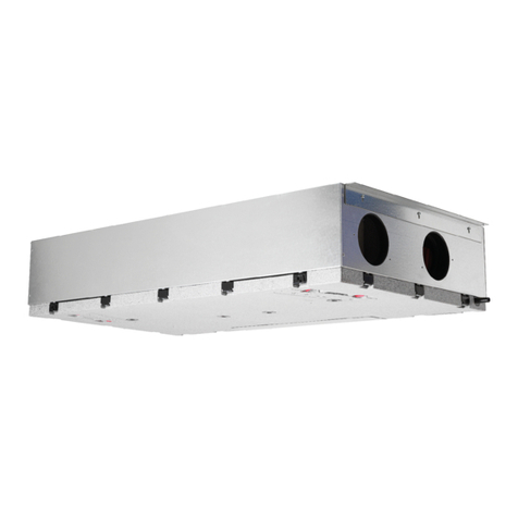
Nibe FLM S45 User manual

UHB EN 1926-1
531275
USER MANUAL
Exhaust air module
FLM S45

LEK
LEK
LEK

41 Important information
4Installation data
5Safety information
5Serial number
5Compatible NIBE heat pumps
6
2 The heating installation – the heart of the
house
6Exhaust air module function
7Maintenance of FLM S45
93 Disturbances in comfort
10Item register
11Contact information
3Table of ContentsFLM S45
Table of Contents

Installation data
FLM S45Product
Serial number
Installation date
Installer
SetFact.
sett.
NameNo.
XDifferential brine in-/outX
100%Exhaust air fan (fan speed, normal mode)X
Serial number must always be given
Certification that the installation is carried out according to instructions in the accompanying installer manual and applicable regulations.
__________________________________________Signed______________________________Date
FLM S45Chapter 1 | Important information4
1 Important information

Safety information
This appliance can be used by children
aged from 8 years and above and persons
with reduced physical, sensory or mental
capabilities or lack of experience and
knowledge if they have been given super-
vision or instruction concerning use of the
appliance in a safe way and understand
the hazards involved. Children shall not
play with the appliance. Cleaning and user
maintenance shall not be made by children
without supervision.
Rights to make any design or technical
modifications are reserved.
©NIBE 2019.
If the supply cable is damaged, only NIBE,
its service representative or similar author-
ised person may replace it to prevent any
danger and damage.
SYMBOLS
NOTE
This symbol indicates danger to person or ma-
chine .
Caution
This symbol indicates important information
about what you should observe when maintain-
ing your installation.
Serial number
The serial number can be found at the bottom left inside
the front cover.
LEK
Caution
You need the product's (14 digit) serial number
for servicing and support.
Compatible NIBE heat
pumps
FLM S45 ventilates the building and preheats the brine,
regardless of which ground source heat pump is in-
stalled, but when FLM S45 is installed together with a
compatible ground source heat pump, it is possible to
adjust settings and read off sensor values etc. in the
heat pump’s display.
COMPATIBLE PRODUCTS
• S1255• S1155
5Chapter 1 | Important informationFLM S45

0 ºC
-3 º C
22 ºC
-3 º C 0 ºC
0 ºC
5 ºC-4 ºC
100 ºC
35 ºC25 ºC
Brine
Refrigerant
Evaporator
Condenser
Expansion valve
Compressor
1
2
Heat source
Czynnik obiegu dolnego źródła
Exhaust air module
function
An exhaust air module uses the heat that is in the
building's ventilation air to heat up the brine.
Brine circuit
An anti-freeze liquid (brine) circulates in a hose (collector)
from the heat pump out to the heat source
(rock/ground/lake). The energy from the heat source is
stored by it heating the brine a few degrees, from about
–3 °C to about 0 °C.
A
The collector then routes the brine to the heat pump’s
evaporator. Here, the brine releases heat energy and the
temperature drops a few degrees. The liquid then returns
to the heat source to retrieve energy again.
B
Refrigerant circuit
Another liquid circulates in a closed system in the heat
pump, a refrigerant, which also passes the evaporator.
The refrigerant has a very low boiling point. In the evapor-
ator the refrigerant receives the heat energy from the brine
and starts to boil.
C
The gas that is produced during boiling is routed into an
electrically powered compressor. When the gas is com-
pressed, the pressure increases and the gas’s temperature
increases considerably, from approx. 5°C to approx. 100°C.
D
From the compressor, gas is forced into a heat exchanger,
condenser, where it releases heat energy to the heating
system in the house, whereupon the gas is cooled and
condenses to a liquid form again.
E
As the pressure is still high, the refrigerant can pass an
expansion valve, where the pressure drops so that the
refrigerant returns to its original temperature. The refriger-
ant has now completed a full cycle. It is routed to the
evaporator again and the process is repeated.
F
Heat medium circuit
The heat energy that the refrigerant produces in the con-
denser is retrieved by the climate system's water, heating
medium, which is heated to 35 °C (supply temperature).
G
Ventilation
The hot air is transferred from the rooms to the heat pump
via the exhaust air module.
J
The fan then routes the air to the exhaust air module heat
exchanger. Here, the air releases the heating energy to
the brine and the air's temperature drops significantly. The
cold air is then blown out of the house.
K
The temperatures are only examples and may vary between different installations and time of year.
FLM S45Chapter 2 | The heating installation – the heart of the house6
2 The heating installation – the
heart of the house

Maintenance of
FLM S45
REGULAR CHECKS
Your exhaust air module requires minimal maintenance
after commissioning. On the other hand, it is recommen-
ded that you check your installation regularly.
If FLM S45 is installed with a compatible heat pump and
something untoward occurs, a message appears regard-
ing the malfunction in the form of various alarm texts in
the heat pump display.
Cleaning the ventilation devices
The building’s ventilation
devices should be cleaned
regularly with, for example,
a small brush to maintain the
correct ventilation.
The device settings must
not be changed.
NOTE
If you take down more than one ventilation
device for cleaning, do not mix them up.
Cleaning the air filter
Clean the FLM S45's air filter regularly, how often de-
pends on the amount of dust in the ventilation air. Select
what is most suitable for your installation.
Caution
The efficiency of the installation can be im-
paired by a dirty air filter.
If FLM S45 is connected to a compatible heat pump,
you receive a reminder to clean the filters in the display.
The default setting for the reminder is every three
months; however, if the power to the heat pump is in-
terrupted, the countdown starts from zero again.
1. Switch off the heat pump.
2. Remove the front hatch by pulling it straight out.
3. Pull out the filter cassette.
4. Remove the filter and shake/vacuum it clean.
5. Check the condition of the filter.
6. Carry out assembly in reverse order.
Even if the filter appears clean, dirt collects in it and this
affects the efficiency of the filter. Therefore, replace it
after 1 years. New filters can be ordered via the installer.
NOTE
Water or other liquids must not be used for
cleaning.
LEK
LEK
Filter
7Chapter 2 | The heating installation – the heart of the houseFLM S45

Checking the condensation water seal
LEK
The condensation hose from FLM S45 has to be shaped
into a water seal. On the rear of S1255 there is a groove
in the insulation for the condensation hose; other com-
patible heat pumps do not have this groove.
Check that there is water in the water seal. If it is empty,
or has a very low water level so that it “gurgles”, it must
be topped up with water.
After a period of operation dust and other particles can
clog the water seal, consequently, you should check
this regularly and clean when necessary.
FLM S45Chapter 2 | The heating installation – the heart of the house8

In most cases, the compatible heat pump notes a mal-
function (a malfunction can lead to disturbance in com-
fort) and indicates this with alarms and action instruc-
tions in the display.
If the malfunction does not appear in the display or
FLM S45 is not connected to a compatible heat pump,
the following tips can be used:
BASIC ACTIONS
Start by checking the following items:
• That the heat pump is running or that the supply cable
to FLM S45 is connected.
• Group and main fuses of the accommodation.
• The property's earth circuit breaker.
LOW OR A LACK OF VENTILATION
• Filter blocked.
– Clean or replace filter (see page 7).
• The ventilation is not adjusted.
– Order ventilation adjustment.
• Exhaust air device blocked or throttled down too
much.
– Check and clean the exhaust air devices (see page
7).
• Fan speed in reduced mode.
– 1.2.1 and select "normal".
If FLM S45 is connected to a compatible heat pump:
Enter menu 1.2.1 and select "normal".
If FLM S45 is connected to another heat pump:
Contact your installer!
• External switch for changing the fan speed activated.
– Check any external switches.
HIGH OR DISTRACTING VENTILATION
• Filter blocked.
– Clean or replace filter (see page 7).
• The ventilation is not adjusted.
– Order ventilation adjustment.
• Fan speed in forced mode.
–If FLM S45 is connected to a compatible heat pump:
Enter menu 1.2.1 and select "normal".
If FLM S45 is connected to another heat pump:
Contact your installer!
• External switch for changing the fan speed activated.
– Check any external switches.
GURGLING SOUND
• Not enough water in the water seal.
– Fill the water seal with water (see page 8)
• Choked water seal.
– Check and adjust the condensation water hose (see
page 8).
9Chapter 3 | Disturbances in comfortFLM S45
3 Disturbances in comfort

C
Compatible NIBE heat pumps, 5
D
Disturbances in comfort, 9
Troubleshooting, 9
G
General pipe connections
Compatible NIBE heat pumps, 5
I
Important information
Installation data, 4
Serial number, 5
Installation data, 4
M
Maintenance of FLM S45, 7
Regular checks, 7
R
Regular checks, 7
S
Serial number, 5
T
The function of the exhaust air module, 6
The heating installation – the heart of the house, 6
Troubleshooting, 9
FLM S45Item register10
Item register

Contact information
DENMARKCZECH REPUBLICAUSTRIA
Vølund Varmeteknik A/S
Industrivej Nord 7B, 7400 Herning
Tel: +45 97 17 20 33
volundvt.dk
Družstevní závody Dražice - strojírna
s.r.o.
Dražice 69, 29471 Benátky n. Jiz.
Tel: +420 326 373 801
nibe.cz
KNV Energietechnik GmbH
Gahberggasse 11, 4861 Schörfling
Tel: +43 (0)7662 8963-0
knv.at
GERMANYFRANCEFINLAND
NIBE Systemtechnik GmbH
Am Reiherpfahl 3, 29223 Celle
Tel: +49 (0)5141 75 46 -0
nibe.de
NIBE Energy Systems France SAS
Zone industrielle RD 28
Rue du Pou du Ciel, 01600 Reyrieux
Tél: 04 74 00 92 92
nibe.fr
NIBE Energy Systems Oy
Juurakkotie 3, 01510 Vantaa
Tel: +358 (0)9 274 6970
nibe.fi
NORWAYNETHERLANDSGREAT BRITAIN
ABK AS
Brobekkveien 80, 0582 Oslo
Tel: (+47) 23 17 05 20
nibe.no
NIBE Energietechniek B.V.
Energieweg 31, 4906 CG Oosterhout
Tel: +31 (0)168 47 77 22
nibenl.nl
NIBE Energy Systems Ltd
3C Broom Business Park,
Bridge Way, S41 9QG Chesterfield
Tel: +44 (0)845 095 1200
nibe.co.uk
SWEDENRUSSIAPOLAND
NIBE Energy Systems
Box 14
Hannabadsvägen 5, 285 21 Markaryd
Tel: +46 (0)433-27 3000
nibe.se
EVAN
bld. 8, Yuliusa Fuchika str.
603024 Nizhny Novgorod
Tel: +7 831 419 57 06
nibe-evan.ru
NIBE-BIAWAR Sp. z o.o.
Al. Jana Pawla II 57, 15-703 Bialystok
Tel: +48 (0)85 66 28 490
biawar.com.pl
SWITZERLAND
NIBE Wärmetechnik c/o ait Schweiz
AG
Industriepark, CH-6246 Altishofen
Tel. +41 (0)58 252 21 00
nibe.ch
For countries not mentioned in this list, contact NIBE Sweden or check nibe.eu for more information.

NIBE Energy Systems
Hannabadsvägen 5
Box 14
SE-285 21 Markaryd
nibe.eu
UHB EN 1926-1 531275
This manual is a publication from NIBE Energy Systems. All product illustrations, facts and
data are based on the available information at the time of the publication’s approval.
NIBE Energy Systems makes reservations for any factual or printing errors in this manual.
©2019 NIBE ENERGY SYSTEMS 531275
WS name: -Gemensamt
WS version: a669
WS release date: 2019-06-28 07:20
Publish date: 2019-08-14 11:18
Other manuals for FLM S45
1
Table of contents
Other Nibe Fan manuals

Nibe
Nibe SAM 42 User manual

Nibe
Nibe Contura C34T User manual

Nibe
Nibe ERS S10-400 User guide

Nibe
Nibe DVC 10-50 User manual

Nibe
Nibe ERS S40-400 User manual

Nibe
Nibe Contura C500 Style User manual

Nibe
Nibe Flakt Contura C600 User manual

Nibe
Nibe ERS S10-400 User manual

Nibe
Nibe GV-HR 130 User guide

Nibe
Nibe Contura C500 Style User manual