manuals.online logo
Brands
  1. Home
  2. •
  3. Brands
  4. •
  5. Nibe
  6. •
  7. Indoor Fireplace
  8. •
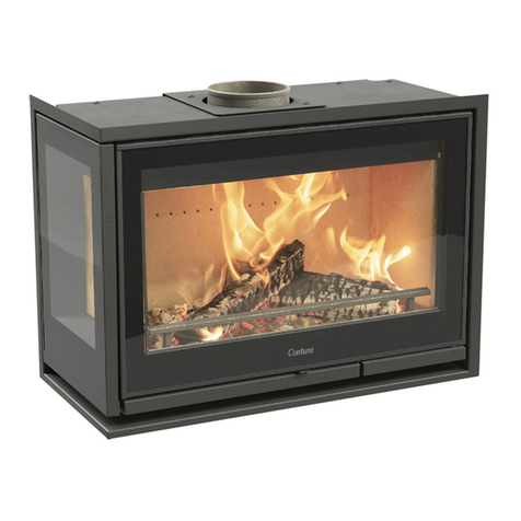
  9. Nibe Contura Ci2 User manual

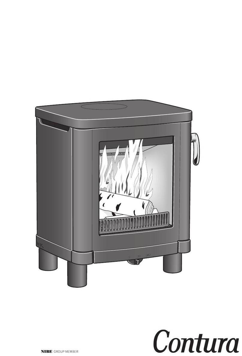
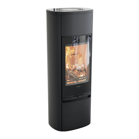
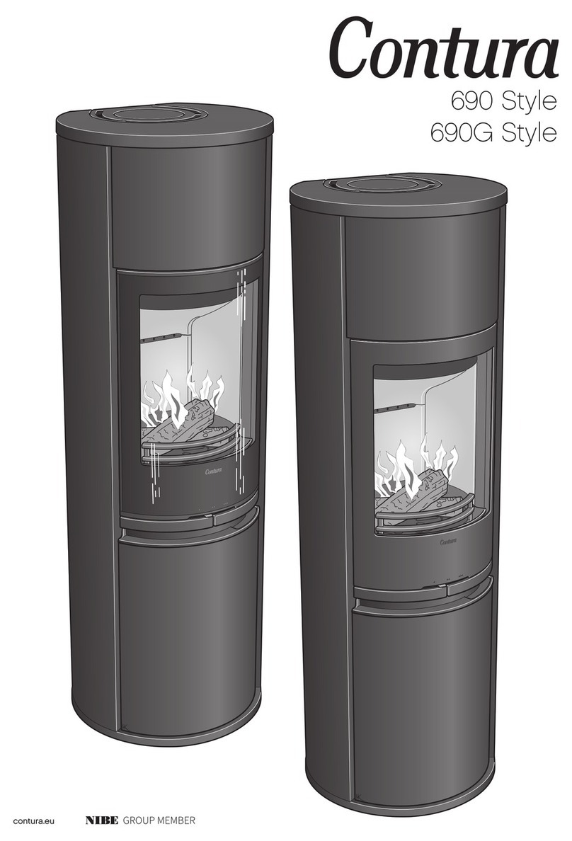
Nibe Contura Ci2 User manual

Ci2
Ci2G
contura.eu
SE
NO FR
GB
Données techniques 25
Déclaration des performances 26
Déclaration CE/UE de conformité 27
Schéma dimensionnel 28
Exemple d’encastrement 30
Montage 32
Fakta 3
Prestandadeklaration 4
EU-försäkran om överrensstämmelse 5
Måttskiss 6
Inbyggnadsexempel 8
Montering 32
Fakta 18
Ytelseserklæring 19
EU-samsvarserklæring 20
Målskisse 21
Innbyggingseksempel 23
Montering 32
Facts 10
Declaration of performance 11
EU Declaration of Confirmit 12
Dimensions diagram 13
Recess example 15
Assembly 32
GB
10
5 kW 600 / 615 mm 550 mm 350 mm 80 kg
Facts
!
Contura reserves the right to change dimensions and procedures specified in these instructions
at any time without notice. Access the latest version at www.contura.eu
Nominal output 5 kW
Efficiency 80,3%
Meets requirements of:
European standard EN-13229
Clean Air Act. (UK)
NS 3059 (NO)
Installation by authorised
technician
This manual contains instructions about how
the insert must be assembled and installed. To
ensure the function and safety of the insert,
the installation should be carried out by a Hetas
trained engineer. Contact one of our dealers who
can recommend suitable installer. When completed,
the installer should inform the local Council/
authority about the new installation.
Building application
These main instructions may give guidance which
would contravene national building regulations.
Please refer to supplementary instructions or ask
your local authority for advice regarding building
regulations.
Before installing a stove or erecting a chimney it
is necessary for you to make a building application
permission to your local authority.
The owner of the house is personally responsible
for ensuring compliance with the mandatory safety
requirements and must have the installation
approved by a qualified inspector. Your local
chimney sweep must also be informed about the
installation as this will affect the routines for
regular chimney-sweeping services.
Structural support
Check that the wood joists are strong enough to
bear the weight of the stove and chimney. The
stove and chimney can usually be placed on a
normal wooden joist in a single occupancy house if
the total weight does not exceed
400 kg.
Hearth plate
Due to the risk of falling embers, a flammable
floor must be protected by a hearth plate. It must
extend 300 mm in front of the stove and 100
mm on each side of the stove, or have a 200 mm
extension on each side of the opening. The hearth
plate can consist of natural stone, concrete, metal
plate or glass. A glass hearth plate is available as
an accessory for these models.
Final inspection of the
installation
It is extremely important that the installation
is inspected by an authorised chimney sweep
before the stove is used. Also read the ”Lighting
instructions”, before lighting for the first time.
The insert becomes very hot
During operation, certain surfaces of the
insert become very hot and can cause
burn injury if touched. Be aware of the
strong heat radiated through the hatch
glass. Placing flammable material closer
than the safe distance indicated may
cause a fire. Pyre lighting can cause quick
gas ignition with the risk of damage to
property and personal injury.
Connection to chimney
• The insert must be connected to a chimney designed to withstand flue gas
temperatures of up to 400°C.
• The stove should not be installed in a chimney serving more than one
appliance.
• The diameter of the connection sleeve is designed to fit chimney pipes
with an external diameter of Ø125 mm. A connection sleeve is available,
as an optional extra, for chimney pipes with an internal diameter of Ø150
mm.
• Normal chimney draw under nominal operation should be between 20-25
Pa close to the connector. The draft is affected both by the length and
area of the chimney, and by how well sealed it is. Minimum recommended
chimney length is 3.5 m and suitable cross section area is 120-175 cm²
(125-150 mm in diameter).
• A flue with sharp bends and horizontal routing reduces the draught in
the chimney. Maximum horizontal flue is 1 m, on the condition that the
vertical flue length is at least 5 m.
• It must be possible to sweep the full length of the flue and the soot
hatches must be easily accessible.
• Carefully check that the chimney is sealed and that there is no leakage
around soot hatches and flue connections.
Supply of combustion air
When an insert is installed, the need for an adequate supply of air to the
room increases. Air can be provided indirectly via a vent in the outer wall or
via a duct from the outside that connects to the sleeve on the underside of
the insert. The required volume of combustion air is about 20 m3/hour.
The connector (accessory) for the combustion air has an external diameter
of 80 mm. When duct routing further than 1 m the pipe diameter must
be increased to 100 mm and a correspondingly larger wall vent must be
selected.
In hot areas, the duct should be insulated with 30 mm mineral wool with a
moisture inhibiting outer cover. It is also important to seal around the hole
in the wall (or floor) of the lead-in using sealant.
A 1 m length of condensation insulated ducting for combustion air is
available as an accessory.
GB
11
PRODUCT
Type Wood burning insert
Trade name Contura i2
Intended area of use Heating of rooms in residential buildings
Fuel Wood
MANUFACTURER
Name NIBE AB / Contura
Address Box 134, Skulptörvägen 10
SE-285 23 Markaryd, Sweden
VERIFICATION
According to AVCP System 3
European standard EN 13229:2001 / A2:2004 / AC:2007
Test institute KIWA UK 61354, NB 0692
D e c l a r a t i o n o f p e r f o r m a n c e a c c o r d i n g
to Regulation (EU) 305/2011
DECLARED PERFORMANCE
ESSENTIAL CHARACTERISTICS PERFORMANCE HARMONISED TECHNICAL
SPECIFICATION
Fire safety Pass
Fire classification A1
Minimum distance to flammable
materials
Rear: 200 mm
Side: 250 mm
Ceiling: 1200 mm
Ceiling: 700 mm (front grate)
Front: 1400 mm
Floor: 275 mm
Fire hazard due to burning fuel falling out Pass EN 13229:2001 / A2:2004 / AC:2007
Cleanability Pass
Emissions from combustion CO: < 1500 mg/ Nm3 (13% O2)
Surface temperatures Pass
Temperature on the handle Pass
Mechanical resistance Pass
Temperature in the space for wood storage NPD
Nominal output 5,0 kW
Efficiency 80,3%
Flue gas temperature at nominal output 269°C
Flue gas temperature in flue spigot NPD
The undersigned is responsible for the manufacture and conformity with the declared performance.
Niklas Gunnarsson, Business area manager NIBE STOVES
Markaryd, April 4, 2022
No. Ci2-CPR-220404
GB
12
EU Declaration of Conformity
Manufacturer NIBE AB / Contura
Address Box 134, Skulptörvägen 10
285 23 Markaryd, Sweden
E-Mail info@contura.se
Website www.contura.eu
Telephone +46 433 275100
THIS DECLARATION OF CONFORMITY IS ISSUED UNDER OUR SOLE RESPONSIBILITY FOR THE FOLLOWING PRODUCT:
Trade name Contura i2
Identification of product www.contura.eu
THE OBJECT OF THE DECLARATION DESCRIBED ABOVE IS IN CONFORMITY WITH -
THE RELEVANT UNION HARMONIZATION LEGISLATION: THE RELEVANT HARMONIZED STANDARDS:
DIR 2009/125/EC EN 13229:2001/A2:2004/AC:2007
REG (EU) 2015/1185 CEN/TS 15883:2010
REG (EU) 2015/1186
REG (EU) 2017/1369
REG (EU) 305/2011
TECHNICAL DOCUMENTATION
Indirect heating functionality: No
Direct heat output: 5,0 kW
Energy Efficiency Index (EEI): 106,4
Test report KIWA UK 61354, NB 0692
CHARACTERISTICS WHEN OPERATING WITH THE PREFERRED FUEL
ITEM SYMBOL VALUE UNIT ITEM SYMBOL VALUE UNIT
HEAT OUTPUT USEFUL EFFICIENCY, BASED ON NET CALORIFIC VALUE (NCV )
Nominal heat output: Pnom 5,0 kW Useful efficiency at nominal
heat output η th,nom 80,3 %
AUXILIARY ELECTRICITY CONSUMPTION TYPE OF HEAT OUTPUT/ROOM TEMPERATURE CONTROL
At nominal heat output elmax - kW Single stage heat output, no room temperature control Yes
At minimum heat output elmin - kW Two or more manual stages, no room temperature control No
In standby mode elSB - kW With mechanic thermostat room temperature control No
With electronic room temperature control No
With electronic room temperature control plus day timer No
With electronic room temperature control plus week timer No
OTHER CONTROL OPTIONS
Room temperature control, with presence detection No
Room temperature control, with open window detection No
With distance control option
Specific precautions for assembly,
installation, or maintenance.
Fire protection and safety distances to combustible building materials must be observed under all circumstances.
A sufficient supply of combustion air must always be guaranteed. Air suction systems can interfere with the combustion
air supply.
FUEL PREFERRED
FUEL OTHER SUITABLE
FUEL ηS (%)
EMISSIONS AT NOMINAL HEAT OUTPUT
PM OGC CO NOx
mg/ Nm3 (13% O2)
Wood logs with moisture content ≤25% Yes No 70,3 <40 <120 <1500 <200
Compressed wood with moisture content <12% No Yes 70,3 <40 <120 <1500 <200
Other woody biomass No No
Non-wood biomass No No
Anthracite and dry steam coal No No
Hard coke No No
Low temperature coke No No
Bituminous coal No No
Lignite briquettes No No
Peat briquettes No No
Blended fossil fuel briquettes No No
Other fossil fuel No No
Blended biomass and fossil fuel briquettes No No
Other blend of biomass and solid fuel No No
The undersigned is responsible for the manufacture and conformity with the declared performance.
Niklas Gunnarsson, Business area manager NIBE STOVES
Markaryd, April 1, 2022
GB
13
600
550
570
60
565
350
235
7
Air inlet Ø80
Ø126
615
550
570
60
565
350
235
7
Air inlet Ø80
Ø126
515 515
Ci2
Furnishings and combustible building elements must be at least 1,4 metre from the front of the insert door.
When connecting to a steel chimney, the requirements for safe distance to the chimney must also be observed.
A clearance of at least 300 mm must be allowed as a safe distance between an uninsulated flue pipe and com-
bustible building elements.
Dimensions diagram
3-sided frame 4-sided frame
GB
14
850 mm
600 mm
150 mm
150 mm
125 mm
Hearth dimensions
The appliance must stand on a constructional hearth which meet
the building regulations and has minimum dimension as shown in
the diagram. Always check that the building has enough bearing
capacity for the heart, stove and chimney. The stove can be loaded
with maximum 100 kg of chimney.
GB
15
Recessing the insert
When recessing the insert, adjacent walls that are not classed as fire walls
or are considered unsuitable for exposure to heat must be protected by
non-combustible building material in accordance with the specifications
below.
All joints on the non-combustible material must be sealed using the method
recommended by the manufacturer. The space between the insert and the
recess must be ventilated in accordance with specifications/dimensions
diagrams.
Please refer to the manufacturer’s installation instructions when connecting
a steel chimney to a top outlet. Observe the requirements for the safe
distance from the steel chimney to combustible materials. Because of the
strong heat radiating from the door, combustible materials must be placed a
minimum of 1,4 m from the door.
The insert must be installed with clearance to the building material, not in
direct contact with it, to allow for thermal expansion of the insert.
Material requirements
The building material must not be combustible.
The thermal conductivity coefficient λ must be maximum 0.14 W/mK.
The building material must always be at least 100 mm thick.
Where the insulation properties of building material are given as a U-value, it
must be maximum 1.4 W/ m²K.
List of suitable materials:
Aerated concrete: λ= 0.12–0.14
Vermiculite: λ= 0.12–0.14
Calcium silicate: λ= 0.09
Sealing
The recess must not go all the way up to the ceiling, leave an air gap of at
least 20 mm closest to the ceiling. The recess must be sealed off above the
convection exhaust. The seal must be 100 mm above the convection exhaust’s
upper edge and must be made of 40 mm non-flammable material according
to the material requirements above. Use heat-resistant silicone, for example,
between the seal and chimney.
Convection air
The convection air ventilates the surround, cools the insert and carries hot
air out into the room. The total sum of the effective cross-section area up
and down must not be less than the stated values. The air intake must be
positioned somewhere between floor level and the bottom of the insert, at
the front or on the sides of the recess. The air exhaust must be positioned
above the highest point of the insert at the front or the sides of the recess.
If the air intakes or exhausts are positioned on the sides, the areas for the
left and right side respectively must be the same size to ensure that the
insert is evenly cooled.
Check the minimum distance to the ceiling.
Convection air in: 200 cm²
Convection air out: 200 cm²
Floor and load-bearing base
Combustible flooring beneath the insert must be protected. The examples
show the floor protected by a 40 mm calcium silicate board.
Ensure that the convection box is placed on a base strong enough to bear the
weight of the stove and chimney.
The base must not block the flow of convection air in the space between the
insert and recess.
Steel chimney on the insert
If the insert is to be connected to a module-based steel chimney, it must be
connected via a chimney support panel (accessory). The weight of the steel
chimney on the insert with the chimney support panel must be maximum
100 kg.
GB
16
55
20
40
500
20 mm Air gap
500
55
40
20
40
20 mm Air gap
!
100
20
20
100
100
500
20
100
100
500
700
max 100
30
min. 460
50
40
Area ut min. 300 cm2
Area in min. 300 cm2
Strålningsplåt
Brandmur
Ci2
The dimensions are the minimum
dimensions, unless otherwise stated.
Wall made of non-combustible material that
is not in contact with combustible material
and therefore has no minimum thickness
requirement.
Wall made of combustible material
Recess example
Aerated wall, comprising at least a 40 mm calcium
silicate board and an air space. There must be a 20
mm air space between the building board and the
combustible wall. The air space must allow air to flow
freely along the lower and upper edges (see diagram
to the right). Diagram of aerated wall
Two calcium silicate board
battens ensure that the air
space is maintained.
Firewall, approved and fully complies with safety
requirements according to the authorised inspection
body. Examples of approved firewalls are 120 mm
solid brick and 100 mm aerated concrete.
It is extremely important that the installation
is inspected by an authorised inspection body
before the insert is used. You should also read
the “Lighting instructions” before lighting the
stove for the first time.
Final inspection of the
installation
GB
17
700
40
30
275
1100
Area out min. 200 cm2
Area in min. 300 cm2
Load bearing base
Combustible wall
max 100
550
1100
40
275
100
40
55
100
Area out min. 200 cm2
Area in min. 300 cm2
Load bearing base
20 mm Air gap
550
40
30
275
1100
100
Area in min. 300 cm2
Load bearing base
Area out min. 200 cm2
Combustible wall
700
min. 100
20
40
40
55
100
275
1100
Area out min. 200 cm2
Area in min. 300 cm2
Heat shield
Load bearing base
20 mm Air gap
max 100
! !
Ci2
Recess example
Always observe the safety distances
to combustible material required by
a steel flue.
The dimensions are the minimum
dimensions, unless otherwise stated.
32
1
2
4
5
67
3
Montering
Om insatsen behöver läggas ned för att förflyttas
bör lösa delar demonteras. Demontering av
eldstadsbeklädnad beskrivs på nästa sida.
1 Stosavsats
2 Eldstadsbeklädnad(Vermiculit)
3 Typskylt
4 Roster
5 Asklåda
6 Eldstadsbotten
7 Serienummer
Prior to installation
If the insert needs to be put down to be moved, loose
components should be removed. Removal of the hearth
cladding is described on the next page.
1 Connector sleeve support
2 Fire bricks (Vermiculite)
3 Type plate
4 Grate
5 Ash pan
6 Hearth base
7 Serial number
Før montering Montage
Hvis innsatsen må legges ned for å flyttes, bør løse
deler demonteres. Demontering av brennplater og
hvelv er beskrevet på neste side.
1 Stussplate
2 Brennplater og hvelv (Vermikulitt)
3 Typeskilt
4 Rist
5 Askeskuff
6 Ildstedsbunn
7 Serienummer
Les éléments non fixés devront être déposés si
l’insert doit être couché pour être déplacé. Le
démontage de l’habillage du foyer est décrite à la
page suivante.
1 Rebord de manchon
2 Habillage du foyer (Vermiculite)
3 Plaque signalétique
4 Grille
5 Cendrier
6 Fond du foyer
7 Numéro de série
SE
NO FR
GB
33
1
2
3
5
6
7
4
Handle with care!
!
34
GB
Note: When refuling - open the air control fully for 3-5 minutes
before closing down to the minimum air setting.
For installation in the UK and in smoke control areas
Contura i2, 5 kW woodburning stoves has been recommended as
suitable for use in smoke control areas. This when burning wood
logs and operated in accordance with these instructions and when
fitted with a permanent stop to prevent closure of the air control
unit beyond 31% open position.
Mandatory for smoke control areas
The permanent stop must be installed if the appliance is to be
used in a smoke control area, this stop must not be removed in
smoke control areas, otherwise an offence will be committed if
the appliance is used without the permanent stop in place.
35
8
9
10
36
11
12
37
535
360
580
Min 275Min 275
NO
Innsatsen kan installeres som peiskassett i eksisterende
godkjent åpent ildsted. På grunn av innsatsens varmeutvidelse
skal det være en luftspalte på minst 10 mm rundt innsatsen.
Installasjon i eksisterende åpent ildsted
Insatsen kan installeras som spiskassett i befintlig godkänd
öppen eldstad. Runt om insatsen skall det vara minst 10 mm
luftspalt, detta pga. insatsens värmeutvidgning.
The insert is designed to be installed as a stove cassette in existing
approved open hearths. There must be an 10 mm air gap around the
insert, to allow for the expansion of the insert when hot.
L’insert peut être installé comme une cassette dans un foyer ouvert
existant et homologué. Un espace d’au moins 10 mm doit être prévu
autour de l’insert, pour des raisons d’expansion thermique.
Installation i befintlig öppen eldstad Installation in existing open hearth
Installation dans un foyer ouvert
SE GB
FR
38
Accessory
Tilbehør
Accessoire
Tillbehör
GB
NO
FR
SE
1
2
3
39
Anslutning till befintlig murad skorsten
För enklast montage rekomenderas att använda flexibel slang
(säljs som tillbehör). Fäst stosen i slangen. Anslut och täta mellan
slangen och skorstenen enligt dess separata anvisning.
Insatsen kan även anslutas med fasta rör som förs upp i skorstenen.
Tilkobling til eksisterende murt skorstein
Det anbefales å bruke fleksibel slange for å gjøre monteringen så
enkel som mulig. (selges som tilbehør). Fest stussen i slangen. Koble
til, og tett mellom slangen og skorsteinen i henhold til separat
anvisning for dette.
Innsatsen kan også kobles til med faste rør som føres opp i
skorsteinen.
Raccordement à une cheminée de maçonnerie
existante
Pour simplifier le montage, il est recommandé d’utiliser un tuyau
flexible (proposé en option). Fixez le manchon dans le tuyau. Raccordez
et scellez entre le tuyau et la cheminé selon les instructions séparées.
L’insert peut également être raccordé avec des conduits fixes dans la
cheminée.
Connection to existing masonry chimney
A flexible hose is recommended for ease of installation
(sold as an accessory). Secure the sleeve in the hose. Connect and seal
carefully between the hose and the chimney according to the separate
instruction.
The insert can also be connected with fixed pipe inserted up the chimney.
SE
NO FR
GB
1
LEK
Ø 5 mm
2
40
3
4
41
x4
5
x4
6

This manual suits for next models

1

Other Nibe Indoor Fireplace manuals

Nibe Contura C620 User manual

Nibe

Nibe Contura C620 User manual

Nibe Contura C810W Style User manual

Nibe

Nibe Contura C810W Style User manual

Nibe Contura 320AG User manual

Nibe

Nibe Contura 320AG User manual

Nibe Contura C890 User manual

Nibe

Nibe Contura C890 User manual

Nibe Contura 690 Style User manual

Nibe

Nibe Contura 690 Style User manual

Nibe Contura Style 896G User manual

Nibe

Nibe Contura Style 896G User manual

Nibe Contura C51L User manual

Nibe

Nibe Contura C51L User manual

Nibe Contura C820T User manual

Nibe

Nibe Contura C820T User manual

Nibe Contura C856G User manual

Nibe

Nibe Contura C856G User manual

Nibe Contura 330 User manual

Nibe

Nibe Contura 330 User manual

Nibe Contura C610AG User manual

Nibe

Nibe Contura C610AG User manual

Nibe Contura C310 User manual

Nibe

Nibe Contura C310 User manual

Nibe Contura C690G User manual

Nibe

Nibe Contura C690G User manual

Nibe Contura 856WG Style User manual

Nibe

Nibe Contura 856WG Style User manual

Nibe Contura Ci8 User manual

Nibe

Nibe Contura Ci8 User manual

Nibe Contura C690T User manual

Nibe

Nibe Contura C690T User manual

Nibe Contura Ci8 User manual

Nibe

Nibe Contura Ci8 User manual

Nibe Contura C690 User manual

Nibe

Nibe Contura C690 User manual

Nibe Contura 856T User manual

Nibe

Nibe Contura 856T User manual

Nibe Contura 556T User manual

Nibe

Nibe Contura 556T User manual

Nibe Contura C320T User manual

Nibe

Nibe Contura C320T User manual

Nibe Contira C50 User manual

Nibe

Nibe Contira C50 User manual

Nibe Contura C520 User manual

Nibe

Nibe Contura C520 User manual

Nibe Contura 856T User manual

Nibe

Nibe Contura 856T User manual

Popular Indoor Fireplace manuals by other brands

SEI FA1137256 Assembly

SEI

SEI FA1137256 Assembly

Monessen Hearth Direct Vent Gas Fireplace BDV400 Installation and operating instructions

Monessen Hearth

Monessen Hearth Direct Vent Gas Fireplace BDV400 Installation and operating instructions

Sirocco SCENIC Spirit Installation and user instructions

Sirocco

Sirocco SCENIC Spirit Installation and user instructions

Flavel Misermatic FRCM1G Installation and maintenance instructions

Flavel

Flavel Misermatic FRCM1G Installation and maintenance instructions

GHP Group Pleasant Hearth PHZCI28LP manual

GHP Group

GHP Group Pleasant Hearth PHZCI28LP manual

Astria Fireplaces VEGA 32 manual

Astria Fireplaces

Astria Fireplaces VEGA 32 manual

SEI FA1009259 Assembly

SEI

SEI FA1009259 Assembly

Regency Fireplace Products Greenfire GF900C-NG2 Owners & installation manual

Regency Fireplace Products

Regency Fireplace Products Greenfire GF900C-NG2 Owners & installation manual

FMI Outland Living 525 quick start guide

FMI

FMI Outland Living 525 quick start guide

Flavel Calypso FNCN**SN Series User instructions

Flavel

Flavel Calypso FNCN**SN Series User instructions

Majestic DVDNV Installation and operating instructions

Majestic

Majestic DVDNV Installation and operating instructions

Napoleon BGD90NT Installation and operation instructions

Napoleon

Napoleon BGD90NT Installation and operation instructions

Jøtul C 550 Rockland Installation and operating instructions

Jøtul

Jøtul C 550 Rockland Installation and operating instructions

Vanguard Crown V1100E Installation and operating instructions

Vanguard

Vanguard Crown V1100E Installation and operating instructions

Town & Country Fireplaces TCWS38D user manual

Town & Country Fireplaces

Town & Country Fireplaces TCWS38D user manual

Unigas TP1030 Installation, user's, and maintenance guide

Unigas

Unigas TP1030 Installation, user's, and maintenance guide

Empire Comfort Systems superb CHBR-16-3 Installation instructions and owner's manual

Empire Comfort Systems

Empire Comfort Systems superb CHBR-16-3 Installation instructions and owner's manual

Nordpeis N-20 U user manual

Nordpeis

Nordpeis N-20 U user manual

manuals.online logo
manuals.online logoBrands
  • About & Mission
  • Contact us
  • Privacy Policy
  • Terms and Conditions

Copyright 2025 Manuals.Online. All Rights Reserved.