Nidec DT-3011J User manual

STROBOSCOPE Weatherproof IP65
DT-3011
J
Read this manual thoroughly before use.
Before use, please carefully read these safety precautions as well as instructions,
and follow them for proper operation.
www.nidec.com/jp/nidec-shimpo
INSTRUCTION MANUAL

1
Be sure to read the entire instruction manual thoroughly before initial set-up, operation and maintenance.
The instruction manual provides two grades of safety warnings: “Danger” and “Caution”.
Each of them is an important description related to safety. Be sure to observe.
This indicates the possibility of fire, severe injury, and even death if a user disregards the instruction
and operates the unit improperly.
This indicates the possibility of minor injury or property damage if a user operates the unit improperly.
However, depending on the circumstances, there is still the possibility that severe injury may result.
Be sure to observe.
We categorize the type of those precautions using the following symbols throughout the
manual.
A prohibited action you must not do.
A forced action you must always do.
Never use in flammable environments.
May result in fire.
Never look directly into the light source.
May result in eye injury
Do not apply strong impact to the unit,
or drop it.
Failure to follow this could result in abnormal
operation.
Avoid the followings.
Water, direct sunlight, condensation, dust, dirt, salt,
iron, oil, chemicals, corrosive and/or combustible
gases
Do not alter, modify or dispose improperly.
Failure to follow this could result in injury due to
abnormal operation.
Operate within 0-35°C(32-95°F)
Failure to follow this could result in malfunction.
Wipe clean the unit with a soft dry cloth if it gets dirty.
Or immerse a cloth in water diluted neutral detergent,
wring it, and wipe clean the unit with it.
Do not use any volatile chemicals, such as benzine,
thinner, or alcohol.
Operate within 35-85%RH
Failure to follow this could result in malfunction.
Since continuously emitting light for long time causes
the unit’s housing to heat up, fix the strobe using a
tripod, etc. (Avoid direct skin contact with the unit, such
as holding it by hand).
Failure to follow this could result in mild burns.
Safety Precautions
Be sure to observe
Danger
Caution
Caution
Danger

2
Contents
1
Overview of this product ..................................................................................................................................................................... 3
2
Before use ............................................................................................................................................................................................... 3
2.1 Checking the supplied items ........................................................................................................................................................... 3
3
Part names and functions ................................................................................................................................................................... 4
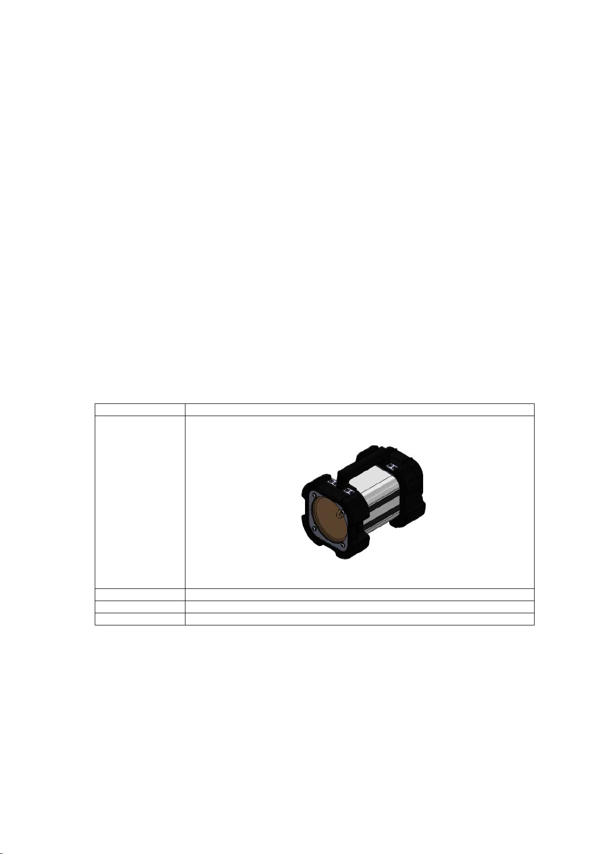
3.1 Main unit ............................................................................................................................................................................................... 4
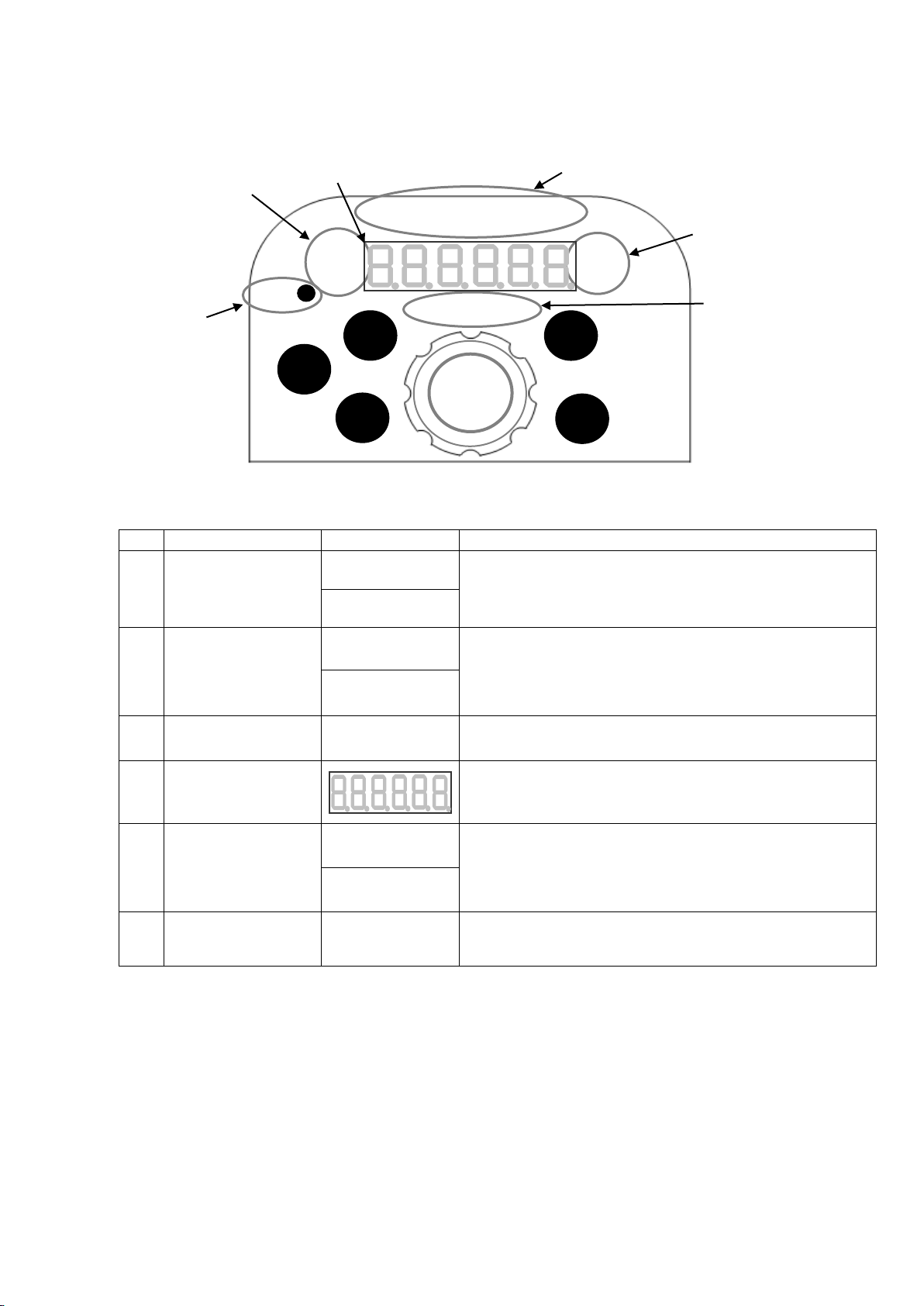
3.2 Operation Panel .................................................................................................................................................................................. 5
3.3 Display ................................................................................................................................................................................................... 6
3.3.1 Part names and function instructions .................................................................................................................................. 6
4
Functions and operations ................................................................................................................................................................... 7
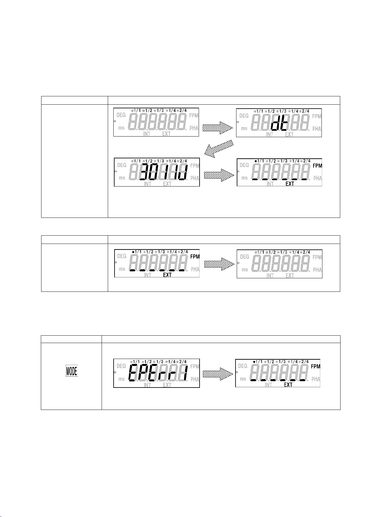
4.1 Power ON/OFF .................................................................................................................................................................................... 7
4.1.1 LAMP ON / OFF .......................................................................................................................................................................... 8
4.1.2 Flash timer ................................................................................................................................................................................... 8
4.1.3 Heat Lamp Indicator .................................................................................................................................................................. 8
4.2 Emission mode and settings .......................................................................................................................................................... 9
4.2.1 How to switch INT and EXT .................................................................................................................................................... 9
4.3 Internal oscillation emission .......................................................................................................................................................... 10
4.3.1 FPM mode setting (INT) ......................................................................................................................................................... 10
4.3.2 PHA mode (INT)........................................................................................................................................................................ 12
4.4 External synchronous emission .................................................................................................................................................. 13
4.4.1 FPM mode setting (EXT) ........................................................................................................................................................ 14
4.4.2 PHA mode setting (EXT) ........................................................................................................................................................ 15
4.5 Divide ratio setting (only for EXT) ................................................................................................................................................. 16
4.5.1 Divide ratio ................................................................................................................................................................................. 16
4.5.2 Divide ratio setting ................................................................................................................................................................... 16
4.6 Function mode .................................................................................................................................................................................. 17
4.6.1 The setting items ..................................................................................................................................................................... 17
4.6.2 Instructions about function mode ....................................................................................................................................... 17
4.7 Saving function ................................................................................................................................................................................. 21
4.7.1 Saving the setting values ...................................................................................................................................................... 21
4.7.2 Initialize ....................................................................................................................................................................................... 22
4.7.3 Initializing the setting values ................................................................................................................................................. 23
4.8 External signal I/O connector specifications and Pin assignment ..................................................................................... 24
4.9 External pulse input ......................................................................................................................................................................... 25
4.10 Lamp replacement ......................................................................................................................................................................... 26
5
Specifications ....................................................................................................................................................................................... 27
5.1 Specifications list .............................................................................................................................................................................. 27
5.2 External dimensions ........................................................................................................................................................................ 28
6
Troubleshooting ............................................................................................................................................................................... 29

3
1
Overview of this product
A stroboscope tachometer is a measurement instrument to measure the speed (cycle) of rotating objects that rotate at a
constant speed, or moving objects that repeatedly operate at a constant cycle. When the rotation (motion) cycle matches with
the flash cycle while the strobe flash is periodically applied on a rotating or moving object, the rotating (moving) object image
appears to stand still. This stroboscope tachometer is the non-contact type, and can be used to read the object frequency when
such a still image appears. Also, a stroboscope can be used to make images of rotating or moving objects stand still or that
slightly move in order to observe their appearance in slow-motion.
Main features
●Wide flash range – 200 to 2500 FPM (flashes per minute)
●Emission in synchronization with the external trigger pulse
●Phase Shift function. (PHA mode)
●Sealed structure to prevent water and dust from entering.
2
Before use
2.1 Checking the supplied items
Check that the four items below are supplied.
DT-3011J
Main unit
One (1) DT-3011J
Accessories
One (1) Power cable (9m)
Instruction Manual
One (1) This document
Warranty
One (1) document

4
3
Part names and functions
3.1 Main unit
Xenon Lamp
Power Switch
Power Connector
Operation Panel

5
3.2 Operation Panel
N
o. Key Function Instructions
①
Power Switch
Turns the power ON/OFF
② Dial (LAMP POWER)
Turn this clockwise or counterclockwise to change the emission frequency and some
setting value.
Press and hold the center of this to turn the lamp ON/OFF.
③ MODE
Press this to switch the LED display as follows
Flashes Per Minute mode (FPM mode)→Phase Shift mode (PHA mode DEG =
delay angle ) → Phase Shift mode ( PHA mode ms = delay time )→FPM mode →…
④ SIG
Select Internal/ External/ Parameter mode.
Internal oscillation emission (referred to as “INT” ):Flash by internal signal
External synchronous emission (referred to as “EXT”):Synchronized flash with external
signal
⑤ DIV Press this while on EXT to change light emission cycle as follows
1/1⇒1/2⇒1/3⇒1/4⇒2/4. (Divided ratio)
⑥ SHIFT Press this while the emission frequency is divided to delay the emission timing by one
pulse.
⑦ ZERO
Press this while on “EXT PHA mode (DEG)” to set the angle displayed
on the LED to “0”.
To turn it back to the original setting, set the time to 0.0 [ms] while on “PHA mode (ms)”
and then press “ZERO” button, or reset the unit.
②
①
③
④
⑦
⑤
⑥

6
3.3 Display
3.3.1 Part names and function instructions
No.
Key
Display
Instructions
① Emission setting display
Each press of “SIG” switches emission settings:
INT :Internal oscillation emission
EXT:External synchronous emission
② Mode display
Each press of “MODE” switches flashing mode and delay type:
FPM:Flashes per minutes mode
PHA:Phase mode
③ Division display 1/1 1/2 1/3 1/4 2/4 Each press of “DIV” switches light emission cycle.
④ Numerical display
Standard Operation: indicates flash rate.
PHA Mode: Angle and Time are displayed
Function Mode: Each setting value is indicated
⑤ Delay type display
Each press of “MODE” switches flashing mode and delay type.
DEG:delay angle
ms:delay time (millisecond)
⑥ Heat Lamp
When the ambient temperature of the Xenon lamp rises above a
certain level, this lamp indicator will flash.
DEG
INT
HEAT
EXT
FPM
PHA
ms
⑥ Heat lamp
④ Numerical display ③
Division display
⑤ Delay type display
②
Mode display
① Emission setting display
HEAT
INT
DEG
EXT
FPM
PHA
ms
1/1 1/2 1/3 1/4 2/4
SHIFT
DIV SIG
MODE
ZERO

7
4
Functions and operations
4.1 Power ON/OFF
Press the power switch when the power is OFF to turn the power ON.
When power is turned ON, the model is indicated, followed by internal oscillation emission or external synchronous emission.
Operation
Display
When the power is OFF
Press the power switch
Press the power switch when the power is ON to turn the power OFF, then the indication goes off.
Operation
Display
When the power is ON
Press the power switch
*When the power is turned ON, the following indication may be displayed.
The following indication is an error message when the reading previously used setting value fails.
Press the “MODE” to return to normal emission screen from the error message display.
Operation
Display
Press the “MODE”
When turning the power on for the first time, “EXT FPM
mode” is displayed. From the second time on, the same as
when the power is previously turned OFF is displayed.
Displayed “dt” for 0.5 sec.
Displayed the model for a sec.
Indicated letters go off
Returns to the normal emission screen
Error message

8
4.1.1 LAMP ON / OFF
Press and hold the center of the dial to turn ON the LAMP when emission setting is displayed on the screen.
Press and hold again while flashing to turn OFF the LAMP.
*When turning the power switch OFF while flashing, it will be turned ON flashing at the next time.
4.1.2 Flash timer
The flashing will automatically cease after 30 minutes from the start of the light emission.
When the flashing stops by this flash timer, the display indicates “OFF”.
Press and hold the dial to return to the previous display.
4.1.3 Heat Lamp Indicator
When the ambient temperature of the Xenon lamp rises above a certain level, the Heat Lamp Indicator will flash.
If the temperature rises more, the Heat Lamp Indicator will remain on and the light emission will cease.
* The temperature tends to rise easily when the emission frequency is higher.
Operation
Display
Press and hold
Operation
Display
Press and hold
Press and hold the dial to flash.
Press and hold again to stop flashing.
After 30 minutes
from the start
Return to the previous display
The ambient temperature of the Xenon lamp
HEAT
Light emission
Less than 75°C (164°F)
Off
Keep flashing
Over 75°C (167°F)
Flash
Keep flashing
Over 80°C (176°F)
On
Stop flashing

9
4.2 Emission mode and settings
Emission mode
詳細
Internal oscillation emission ( “INT” )
Flash at the set frequency.
External synchronous emission ( “ EXT” )
Flash in synchronization with an external trigger pulse input.
Function mode
Configure the settings.
4.2.1 How to switch INT and EXT
Each press of “SIG” switches “INT” and “EXT”.
FPM mode
INT
Division
Shift the timing of flash
EXT
FPM mode Display external input pulse frequency
Power OFF
Displays the model
Power ON
Turn the dial (CW) Increase the emission count (frequency)
Turn the dial (CCW)
Decrease the emission count (frequency)
PHA mode
ms
Turn the dial (CW) Increase the time [ms]
Turn the dial (CCW)
Decrease the time [ms]
PHA mode
DEG
Turn the dial (CW)
Increase the angle (1° to 359°)
Turn the dial (CCW)
Decrease the angle (359° to 1°)
PHA mode
ms
Turn the dial (CW) Increase the time [ms]
Turn the dial (CCW)
Decrease the time [ms]
PHA mode
DEG
Turn the dial (CW) Increase the angle (1° to 359°)
Turn the dial (CCW)
Decrease the angle (359° to 1°)

10
4.3 Internal oscillation emission
・On “INT”, the Xenon lamp flashes at the displayed emission value.
・”INT” has the following 2 mode settings.
Mode settings
FPM mode
PHA mode
Instructions Set the emission count per minute
[FPM] (flashes per minute)
Shift the timing of flash.
The phase can be changed by a
degree or a millisecond.
( One cycle is 360°)
Display of INT
4.3.1 FPM mode setting (INT)
The emission count (frequency) can be set in FPM mode.
Turn the dial in a CW direction to increase the emission count, and in a CCW direction to decrease it.
(Turn the dial fast to change the setting value greatly, and slowly to change it slightly.)
Operation
Display
Increase / decrease
the emission value
(frequency)
Press “SIG” to
switch to the “EXT”
CW
Decrease
Minimum value is 200
CCW Increase
Maximum value is 2500
“INT” “EXT”
Mode display
The emission count (frequency)
Display “INT”
Divide ratio

11
Press
“MODE” to
switch to PHA mode
(DEG)
FPM mode
PHA mode (DEG)

12
4.3.2 PHA mode (INT)
When the rotation (motion) cycle of a measured object matches with the strobe flash cycle, the measured object appears to stand
still. Use the PHA mode in order to adjust the stop angle (position).
The phase can be changed by 1° using dial within the range between 1° and 359° in the PHA mode.
Press “MODE” to switch to PHA mode (ms). (The phase can be changed by 0.1[ms] within the range between 0.0 and 299.2 [ms].)
A time longer than the light emission cycle cannot be set. (PHA mode ms)
Press “MODE” in PHA mode (ms) to switch to FPM mode.
Operation
Display
Increase / decrease
Delay angle / time
Press “MODE” to switch
to PHA mode (ms)
Press “MODE” to switch
to FPM mode
Decrease delay angle
Increase delay angle
Decrease delay time Increase delay time
CCW
CW
CCW
CW
PHA mode (ms)
FPM mode
PHA mode (DEG)
PHA mode (ms)

13
4.4 External synchronous emission
・External synchronous emission is the function to emit a strobe flash in synchronization with an external trigger pulse input.
・You can set which edge of the external trigger pulse triggers emission, the rising edge or falling edge.
・A timing (delay) from the external trigger pulse input with the strobe flash emission can be optionally set using time and angle.
・EXT has the following 2 mode settings.
Mode setting
FPM mode
PHA mode
Instruction
Display the measured value of the
emission count (frequency).
The unit is FPM (flashes per minute)
Shift the timing of flash.
The phase can be changed by a
degree or a millisecond.
( One cycle is 360°)
*If the external trigger pulse cycle is beyond the specifications range, the following letters are indicated.
[Without the delay angle / time setting]
Measurable range 180 to 2750 [fpm]
[With the delay angle setting]
Measurable range 180 to 2750 [fpm]
[With the delay time setting]
Measurable range 180 to 2750 [fpm]
When the external input pulse frequency goes below 180 [fpm],
underlines are displayed.
When the external input pulse frequency
goes beyond 2750[fpm]
,
overlines are displayed.
When the external input pulse frequency goes below 180 [fpm],
an underline on the first, left two digits is displayed.
When the external input pulse frequency goes beyond 2750 [fpm]
,
an overline on the first, left two digits is displayed.
When the external input pulse frequency goes below 180 [fpm],
an underline on the first, left two digits is displayed.
When the external input pulse frequency goes beyond 2750 [fpm],
an overline on the first, left two digits is displayed.
Mode display
Display “EXT”
Division display
Measured value of the
emission count (frequency)

14
4.4.1 FPM mode setting (EXT)
Operation
Display
Press “MODE” to switch
to PHA mode (DEG)
Press “SIG” to switch to
INT
EXT FPM mode PHA mode (DEG)
INT FPM mode

15
4.4.2 PHA mode setting (EXT)
Delay emission can be set within the input signal range between 180 and 2750[fpm].
In the PHA mode, the phase from the external trigger pulse entry to strobe flash emission can be changed by 1° using the dial
within the range between 1° and 359°.
Press “MODE” to switch to PHA mode (ms).
The phase can be changed by 0.1 [ms] within the range between 0.0 and 332.4 [ms].
A time longer than the light emission cycle cannot be set. (PHA mode ms)
Press “ZERO” to set the displayed angle to “0”. (PHA mode DEG)
Press “MODE” in PHA mode (ms) to switch to FPM mode.
Operation
Display
Increase / decrease
Delay angle / time
Press “MODE” to switch
to PHA mode (ms)
Press “MODE” to switch
to FPM mode
Press “ZERO” to set the
displayed angle to “0”
(Only for EXT)
Decrease delay angle Increase delay angle
Decrease delay time
CCW
CW
CCW
CW
PHA mode (ms)
FPM mode
Display “0”.
The emission timing remains delayed.
Increase delay time

16
4.5 Divide ratio setting (for EXT)
4.5.1 Divide ratio
Flash as follows in accordance with the divide ratio.
4.5.2 Divide ratio setting
Operation
Display
Each press of ”DIV”
switches divide ratio.
(for EXT)
Input pulse
1
2
3
4
5
6
7
8
9
10
MODE 1/1
MODE 1/2
MODE 1/3
MODE 1/4
MODE 2/4
1
3
4
5
6
7
8
9
10
1
3
5
7
9
1
4
7
10
1
5
9
1
2
5
6
9
10
2
1/1 1/2
1/4
2/4
1/3

17
4.6 Function mode
Turn the power ON while pressing the “MODE” to enter the function mode.
During the function mode, turn the dial (CW/CCW) to change the settings.
And press “MODE” to save the setting and move to the next setting item. (F1⇒F2⇒F3 end)
If the power is turned OFF in the middle of the function mode, the changed value will not be saved in the memory.
4.6.1 The setting items
The setting items in the following table can be configured in the function mode.
F1
Trigger edge setting (for EXT)
Flash in the rising edge.
Flash in the falling edge.
F2 Choose the input circuit
Open collector input
Voltage pulse input
F3 Measurement range setting (for INT)
The maximum value of the emission count can be set within the range between 200 and 2500 [fpm]
(The value is limited to the maximum.)
4.6.2 Instructions about function mode
How to move to function mode.
Turn the power ON while pressing the “MODE” to enter the function mode.
Operation
Display
The power switch ON
while pressing “MODE”
Turn the power ON
while pressing “MODE”
Displays “Func” for two seconds
And move to f
unction mode 1

18
In function mode 1, in which the edge of the external pulse triggers emission, the rising edge or falling edge, can be set (for EXT).
Operation
Display
Change
the setting value
Go to
function mode 2
*This setting changes the timing of emission as shown in the following figure.
Indicates alternately
Go to function mode 2
*Previous setting value
The default setting is “L-H”
CCW
CW
CCW: L-H (Rising edge) CW: H-L (Falling edge)
Turn the dial and it will stop
i
ndicating alternately.
● The timing of emission
External trigger pulse
Flash
at the rising edge
Flash at the falling edge

19
In function mode 2, the input circuit setting can be changed.
Operation
Display
Change
the setting value
Go to
function mode 3
Indicates alternately
Go to function mode 3
*Previous setting vale
The default setting is “OFF”
CCW
CW
CCW:OFF
Voltage pulse input
(Pull down the external input circuit)
CW:On
Open collector input
(Pull up the external input circuit)
Turn the dial and it will stop
indicating alternately.
Table of contents
Other Nidec Test Equipment manuals

Nidec
Nidec Shimpo DT-315AEB-NIST User manual

Nidec
Nidec DT-311J User manual

Nidec
Nidec ST-5100 User manual

Nidec
Nidec ST-5000 User manual

Nidec
Nidec Shimpo ST-320BL User manual

Nidec
Nidec DT-3015P User manual

Nidec
Nidec Shimpo DT-311J-230V User manual

Nidec
Nidec DT-366 User manual

Nidec
Nidec DT-311D User manual

Nidec
Nidec TNC Series User manual