Nidec DT-3015N User manual

PRESENTED BY
JPBOWLIN.COM
817.332.8116
J.P. Bowlin is a quality-driven Calibration Company
that has provided calibration, repair and sales
of all types of weighing and measurement products since 1931.

97771A
STROBOSCOPE
DT-3015N
Readthismanualthoroughlybeforeuse.
Beforeuse,pleasecarefullyreadthesesafetyprecautionsaswellasinstructions,
andfollowthemforproperoperation.
www.nidec.com/jp/nidec-shimpo
INSTRUCTION MANUAL

1
Besuretoreadtheentireinstructionmanualthoroughlybeforeinitialset-up,operationandmaintenance.
The instruction manual provides two grades of safety warnings: “Danger” and “Caution”.
Eachofthemisanimportantdescriptionrelatedtosafety.Besuretoobserve.
This indicates the possibility of fire, severe injury, and even death if a user disregards the instruction
andoperatestheunitimproperly.
Thisindicatesthepossibilityofminorinjuryorpropertydamageifauseroperatestheunitimproperly.
However,dependingonthecircumstances,thereisstillthepossibilitythatsevereinjurymayresult.
Besuretoobserve.
We categorize the type of those precautions using the following symbols throughout the
manual.
Aprohibitedactionyoumustnotdo.
Aforcedactionyoumustalwaysdo.
Neveruseinflammableenvironments.
Mayresultinfire.
Neverlookdirectlyintothelightsource.
Mayresultineyeinjury.
Donotapplystrongimpacttotheunit,
ordropit.
Failuretofollowthiscouldresultinabnormal
operation.
Avoidthefollowings.
Water,directsunlight,condensation,dust,dirt, salt,
iron, oil,chemicals,corrosiveand/orcombustible
gases.
Donotalter,modifyordisposeimproperly.
Failuretofollowthiscouldresultininjurydueto
abnormaloperation.
Operatewithin0-35°C(32-95°F)
Failuretofollowthiscouldresultinmalfunction.
Wipecleantheunitwithasoftdryclothifitgetsdirty.
Or immerse aclothin water dilutedneutral detergent,
wringit,andwipecleantheunitwithit.
Do not use any volatile chemicals, such as benzine,
thinner,oralcohol.
Operate within45-85%RH
Failuretofollowthiscouldresult inmalfunction.
Since continuously emitting light for long time causes
the unit’s housing to heat up, fix the strobe using a
tripod,etc.(Avoiddirectskincontactwiththeunit,such
asholdingitbyhand).
Failuretofollowthiscouldresultinmildburns.
Danger
Caution
Caution
Danger
Safety Precautions
Be sure to observe

2
Contents
1Overviewofthisproduct......................................................................... 3
2Beforeuse..................................................................................... 3
2.1Checkingthesupplieditems ..................................................................... 3
2.2Charging...................................................................................... 4
2.2.1Chargingmethod........................................................................... 4
2.2.2Indicationoflowbatteryvoltage(LOWBAT).................................................... 5
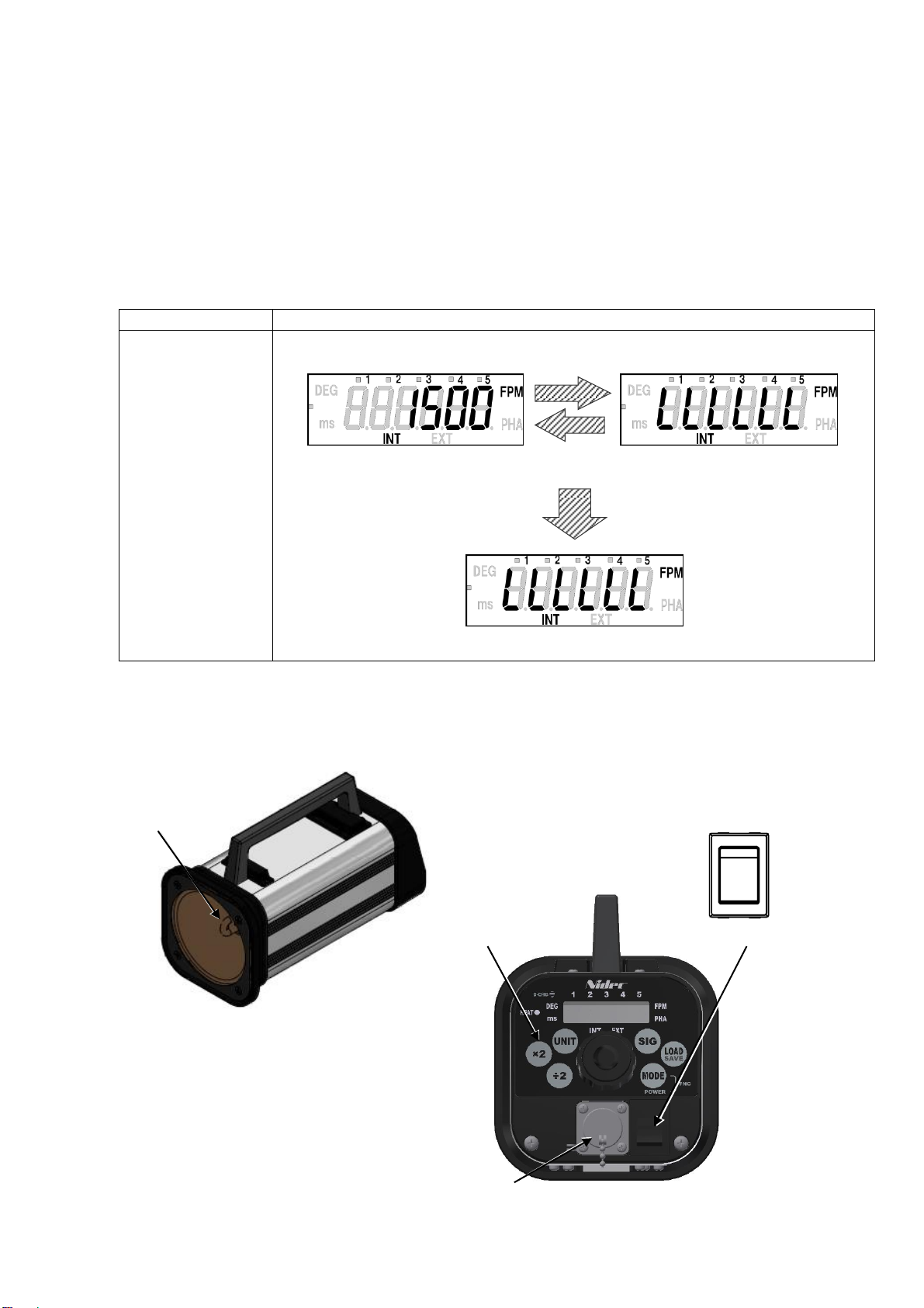
3Partnamesandfunctions...................................................................... 5
3.1Mainunit...................................................................................... 5
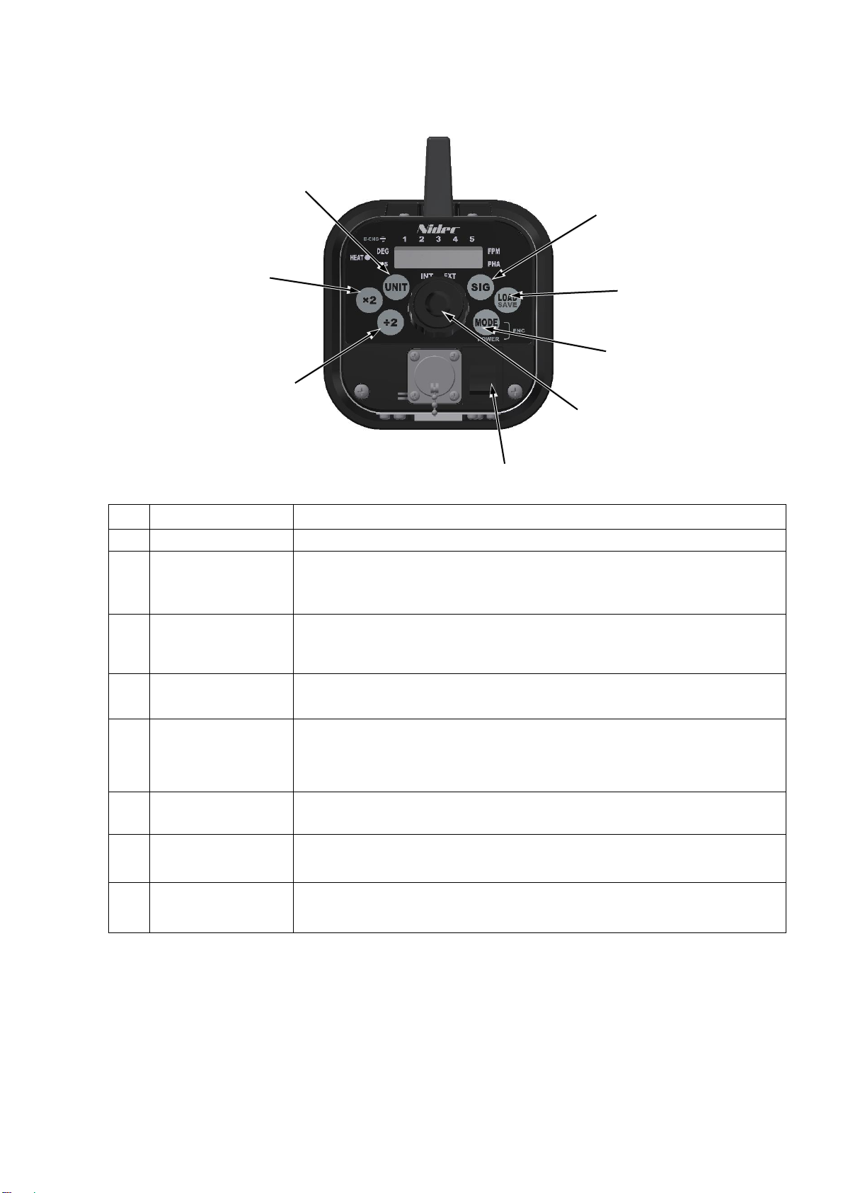
3.2OperationPanel................................................................................ 6
3.3Display ....................................................................................... 7
3.3.1Partnamesandfunctioninstructions.......................................................... 7
4Functionandoperations......................................................................... 8
4.1PowerON/OFF................................................................................ 8
4.1.1LAMPON/OFF ............................................................................ 9
4.1.2Flashtimer ................................................................................ 9
4.1.3HeatLampIndicator ........................................................................ 9
4.2Emissionmodeandsettings .................................................................... 10
4.2.1HowtoswitchINTandEXT ................................................................. 10
4.3Internaloscillationemission..................................................................... 11
4.3.1FPMmodesetting(INT)..................................................................... 11
4.3.2PHAmode(INT)........................................................................... 13
4.4Externalsynchronousemission ................................................................. 14
4.4.1FPMmodesetting(EXT).................................................................... 15
4.4.2PHAmodesetting(EXT).................................................................... 16
4.5Functionmode................................................................................ 17
4.5.1Thesettingitems.......................................................................... 17
4.5.2Instructionsaboutfunctionmode ............................................................ 18
4.6Savingfunction ............................................................................... 24
4.6.1Savingthesettingvalues ................................................................... 24
4.6.2Howtosavethesettingvalues............................................................... 25
4.6.3Initialize.................................................................................. 26
4.6.4Initializingthesettingvalues................................................................. 27
4.7 Readingmemoryfunction..................................................................... 28
4.7.1Readingvalues ........................................................................... 28
4.7.2Howtoreadthememory.................................................................... 28
4.8ExternalsignalI/OconnectorspecificationsandPinassignment...................................... 29
4.9Externalpulseinput............................................................................ 30
4.10Externalpulseoutput ......................................................................... 30
4.11Lampreplacement............................................................................ 31
4.12Batteryreplacement .......................................................................... 32
5Specifications................................................................................. 33
5.1Specificationslist.............................................................................. 33
5.2Externaldimensions........................................................................... 34
6Troubleshooting............................................................................... 35

3
1Overviewofthisproduct
A stroboscope tachometer is a measurement instrument to measure the speed (cycle) of rotating objects that rotate at a
constant speed, or moving objectsthat repeatedly operate at aconstant cycle.Whenthe rotation (motion) cyclematches with
the flash cycle while the strobe flash is periodically applied on a rotating or moving object, the rotating (moving) object image
appearstostandstill.Thisstroboscopetachometeristhenon-contacttype,andcanbeusedtoreadtheobjectfrequencywhen
such a still image appears. Also, a stroboscope can be used to make images of rotating or moving objects stand still or that
slightlymoveinordertoobservetheirappearanceinslow-motion.
Mainfeatures
●Wideflashrange–30to35000FPM(flashesperminute)
●Emissioninsynchronizationwiththeexternaltriggerpulse
●PhaseShiftfunction.(PHAmode)
●Rechargeable
2Beforeuse
2.1Checkingthesupplieditems
Check that thefiveitemsbelowaresupplied.
Mainunit
One(1)DT-3015N
Accessories
One(1)ExternalsignalI/Oconnector(8pins) RM15WTPZ-8S(71)
One(1)DedicatedACadapter(3m)
InstructionManual
One(1)Thisdocument
Warranty
One(1)document

4
2.2Charging
Besuretochargethebatterybeforeinitialuse.
Beforecharging,besuretocheckthatthepoweristurnedOFF.
Pleasecheck the state of the power switchOFFwiththepicture in “3.1 Main unit” onpage6.
2.2.1 Chargingmethod
TurnthepowerOFF,andconnecttheACadapter'sconnectortothemainunit.
NextinserttheACadapter'sACplugintoanoutlet.Thebatterylamplightsup, andchargingstarts.
Chargingiscompleteinapproximately2hours,andthenthecharginglampgoesoff.
Thebatterylamp(B-CHG)
State
Off
ACadapternotconnected,orChargingcomplete
Flash
Chargingerror(Stopcharging)
Continuouslight
Charging
*Be sure to usethe suppliedACadapter.
*Useat theambienttemperature15°C orhigher.
(Iftheambienttemperatureislowerthan15°C,Chargingmaynotbepossible.)
*If thebattery overheats, acharging errormay occur.
Inthiscase, letthe internaltemperaturedecreaseandthenreconnecttheACadapter.
Note1) WhenthepoweristurnedONduringcharging,chargingiscanceledandemissionstarts.Whentheunituses
theACadapterasitspower source, itisnot charged. (Notethat emissionand chargingcannot beperformed
simultaneously.)
Note2) Thoughtheunitcanbecharged whilebatterypowerstill remains, chargingwillstillend whenfullycharged.
Itisrecommended, however, thattheunit becharged whenthe batteryhasrunout ("LLLLLL" isindicatedon
thedisplay)toavoidreducingthebatterylifeitself.
Note 3) Ifthe unitischargedimmediatelyafteralongemissiontimeat ahighambienttemperature,thetemperature
detectioncircuitwill turnon, andthecharginglampmay notlightup.Inthatcase,disconnecttheACadapter,
andlettheunitcool.Whentheproducttemperaturehasdecreased,connecttheACadapteragainandstart
charging.
Note4) Usinginahightemperatureenvironmentmayshortenthebatterylife.
Removetheconnectorcover,
andconnecttheACadapter
Neverchargetheunitunderthefollowingconditions.
Adapterof
anotherdevice
・UsinganotherACadapter thansupplied
・Chargingnearflammablematerials
Oil

5
2.2.2Indicationoflowbatteryvoltage(LOWBAT)
If theremainingbatterydecreasesbelowthespecifiedamount,thebatteryvoltageisloweredandthenumberdisplayis
changedtoindicatethe currentsettingvalueand"LLLLLL"alternately.Emissioncanbeperformedevenwhenthebattery
voltageislow.
If theremainingbatterydecreasesfurther, thenumberdisplayindicatesonly "LLLLLL", which providestheemissionstop
status. Pressthepower switch,and shut off thepowerimmediately.In eithercase, chargethe unitaccordingto the
procedurein"2.2.1 Chargingmethod".
Operation
Display
When the power is
ON
Pressthepower
switch,immediately
3Partnamesandfunctions
3.1Mainunit
XenonLamp
Power Switch
PowerCable
OperationPanel
Indicatesalternately
Indicationofemissionstop
Theremainingbatterydecreasefurther
Thenormaldisplay
(thisdisplaydiffersdependingoneachmode)
Indicationoflowbatteryvoltage
ThesameLEDastheleftlightsup
PowerOFF
PowerON
*Thisfigureshowswhenthepowerisoff

6
3.2OperationPanel
No.
Key
FunctionInstructions
①
PowerSwitch
TurnsthepowerON/OFF
②
Dial(LAMPPOWER)
Turnthisclockwiseorcounterclockwisetochangetheemissionfrequencyandsome
settingvalue.
PressandholdthecenterofthistoturnthelampON/OFF.
③
MODE
PressthistoswitchtheLEDdisplayasfollows
FlashesPerMinutemode(FPMmode) →PhaseShiftmode (PHAmodeDEG=
delay angle ) → Phase Shift mode ( PHA mode ms = delay time ) →FPM mode →…
④
LOAD(SAVE)
Pressthistoloadthesavedsettings.
Also,Pressandholdthistosavethecurrentdisplayandmodesettings.
⑤
SIG
Select Internal/ External/ Parametermode.
Internal oscillation emission (referred to as “INT” ):Flashbyinternalsignal
External synchronous emission (referred to as “EXT”):Synchronizedflashwithexternal
signal
⑥
UNIT
Eachpressofthisswitchesthedelaytypeasfollowing,
delay angle(DEG) → delay time(ms) → DEG → ms
⑦
×2
PressthiswhileonINTtodoublethecurrentsetemissioncount(frequency).
(*Ifthedoublecountisoverthantheflashrange,nothingwillchangeonthedisplay.)
⑧
÷2
PressthiswhileonINTtohalvethecurrent setemissioncount (frequency).
(*Ifthehalfcountislowerthantheflashrange,nothingwillchangeonthedisplay.)
②
①
③
④
⑧
⑥
⑦
⑤

7
3.3Display
3.3.1Partnamesandfunctioninstructions
No.
Key
Display
Instructions
①
Emissionsettingdisplay
Each press of “SIG” switches emission settings.
INT :Internaloscillationemission
EXT:Externalsynchronousemission
②
Modedisplay
Each press of “MODE” switches flashing mode and delay type.
FPM:Flashesperminutesmode / PHA:Phasemode
③
SELECTnumberdisplay
12345
Thisindicatesthememoriesforsaving.(calledSELECTnumber)
Each press of “LOAD” switches SELECT number (1 to 5)
④
Numericaldisplay
StandardOperation:indicatesflashrate.
PHAMode:AngleandTimearedisplayed.
FunctionMode:Eachsettingvalueisindicated.
⑤
Batterylamp
Lightsupwhilecharging,andgoesoffwhenchargingiscomplete.
Flashesifchargingerror.
⑥
Delaytypedisplay
Each press of “MODE” switches flashing mode and delay type.
DEG:delayangle / ms:delaytime(millisecond)
⑦
Heatlamp
WhentheambienttemperatureoftheXenonlamprisesabovea
certainlevel,thislampindicatorwillflash.
⑦Heatlamp
③Numericaldisplay
④SELECTnumberdisplay
⑥Delaytypedisplay
②Modedisplay
①Emissionsettingdisplay
HEAT
INT
DEG
EXT
FPM
PHA
ms
1
2
3
4
5
×2
UNIT
SIG
LOAD
SAVE
MODE
÷2
B-CHG
⑤Batterylamp
DEG
INT
HEAT
EXT
FPM
PHA
ms
B-CHG

8
4Functionandoperations
4.1PowerON/OFF
PressthepowerswitchwhenthepowerisOFFtoturnthepowerON.
WhenpoweristurnedON,themodelisindicated,followedbyinternaloscillationemissionorexternalsynchronousemission.
Operation
Display
When the power is
OFF
Pressthepower
switch
PressthepowerswitchwhenthepowerisONtoturnthepowerOFF,thentheindicationgoesoff.
Operation
Display
WhenthepowerisON
Pressthepowerswitch
*WhenthepoweristurnedON,thefollowingindicationmaybedisplayed.
Thefollowingindicationisanerrormessagewhenthereadingpreviouslyusedsettingvaluefails.
Press the “MODE” to return to normal emission screen from the error message display.
Operation
Display
Press the “×2”
Displayedthemodelforasec.
When turning the power on for the first time, “EXT FPM
mode” isdisplayed. Fromthesecondtimeon,thesameas
whenthepowerispreviouslyturnedOFFisdisplayed.
Indicatedlettersgooff
Returnstothenormalemissionscreen
Errormessage
Displayed “dt” for 0.5 sec.

9
4.1.1LAMPON/OFF
PressandholdthecenterofthedialtoturnONtheLAMPwhenemissionsettingisdisplayedonthescreen.
PressandholdagainwhileflashingtoturnOFFtheLAMP.
*WhenturningthepowerswitchOFFwhileflashing,itwillbeturnedONflashingatthenexttime.
4.1.2Flashtimer
WhentheFlashtimerissettoavalueotherthan0[minutes]inFunctionmode3,
theflashingwillautomaticallyceaseaftersettimefromthestartofthelightemission.
When the flashing stops by this flash timer, the display indicates “OFF”.
Pressandholdthedialtoreturntothepreviousdisplay.
4.1.3HeatLampIndicator
WhentheambienttemperatureoftheXenonlamprisesaboveacertainlevel,theHeat LampIndicatorwillflash.
If thetemperaturerisesmore,theHeat LampIndicatorwill remainonandthelight emissionwillcease.
*Thetemperaturetendstorisemorequicklythehighertheemissionfrequencyisset.
TheambienttemperatureoftheXenonlamp
HEAT
Lightemission
Lessthan65°C(149°F)
Off
Keepflashing
Over65°C(149°F)
Flash
Keepflashing
Over70°C(158°F)
On
Stopflashing
Operation
Display
Pressandhold
Operation
Display
Pressandhold
Pressandholdthedialtoflash.
Pressandholdagaintostopflashing.
Returntothepreviousdisplay
Aftersettimefromthestart

10
4.2Emissionmodeandsettings
Emissionmode
Instructions
Internal oscillation emission ( “INT” )
Flashatthesetfrequency.
External synchronous emission ( “ EXT” )
Flashinsynchronizationwiththeexternaltriggerpulse.
Functionmode
Configurethesettings.
4.2.1HowtoswitchINT andEXT
Each press of “SIG” switches “INT” and “EXT”.。
PowerOFF
OFF
Displaysthemodel
PowerON
FPMmode
INT
PHAmode
Savingfunction
Readthesavedvalue.(SELECTnumber)
Pressandhold
Confirmsaving ⇒Returntothepreviousdisplay
PHAmode
EXT
FPMmode
Displayexternalinputpulsefrequency
Confirmsaving ⇒
Returntothepreviousdisplay
Turnthedial
Increase/decrease
theemissioncount(frequency)
Turnthedial
Increase/decrease
thedelayangleorthedelaytime
Turnthedial
Increase/decrease
thedelayangleorthedelaytime

11
4.3Internaloscillationemission
・On “INT”, the Xenon lamp flashes at the displayed emission count.
・”INT” has the following 2 mode settings.
Modesettings
FPMmode
PHAmode
Instructions
Set the emission count per minute
[FPM](flashesperminute)
Shiftthetimingofflash.
The phase can be changed by a
degreeoramillisecond.
(Onecycleis360°)
DisplayofINT
4.3.1FPMmodesetting(INT)
Theemissioncount(frequency)canbesetinFPMmode.
TurnthedialinaCWdirectiontoincreasetheemissioncount,andinaCCWdirectiontodecreaseit.
(Turnthedialfasttochangethesettingvaluegreatly,andslowlytochangeitslightly.)
Operation
Display
Increase/decrease
Theemissioncount
(frequency)
Press “SIG” to
switch to the “EXT”
Modedisplay
Theemissioncount(frequency)
Display“INT”
SELECTnumber
CW
Decrease
Minimumvalueis30
CCW
Increase
Maximumvalueis35000
INT
EXT

12
Press “×2”to double
the current set the
emissioncount
Press “÷2”to halve
the current set the
emissioncount
Press “MODE” to
switchtoPHAmode
FPMmode
PHAmode
*Ifitisoverthantheflashrange,
nothingwillchangeonthedisplay.
*Ifitislowerthantheflashrange,
nothingwillchangeonthedisplay.

13
4.3.2PHAmode(INT)
Whentherotation(motion)cycleofameasuredobjectmatcheswiththestrobeflashcycle,
themeasuredobjectappearstostandstill.UsethePHAmodeinordertoadjustthestopangle(position).
Thephasecanbechangedby1°usingdialwithintherangebetween1°and359°inthePHAmode.
Press “UNIT” to switch to PHA mode (ms).
(Thephasecanbechangedby0.01[ms]withintherangebetween0.00and999.99[ms]andby0.1[ms]withintherange
between1000.0and1994.4[ms].)
Atimelongerthanthelightemissioncyclecannotbeset.(PHAmodems)
Press “MODE” in PHA mode to switch to FPM mode.
Operation
Display
Increase/decrease
Delayangle/time
Each press of “UNIT”
switchesDEGtoms
Press “MODE” to switch
toFPMmode
Decreasedelayangle
Increasedelayangle
PHAmode(ms)
CCW
CW
CCW
CW
PHAmode
FPMmode
PHAmode(DEG)
Decreasedelaytime
Increasedelaytime

14
4.4Externalsynchronousemission
・Externalsynchronousemissionisthefunctiontoemitastrobeflashinsynchronizationwithanexternaltriggerpulseinput.
・Youcansetwhichedgeoftheexternaltriggerpulsetriggersemission,therisingedgeorfallingedge.
・Atiming(delay)fromtheexternaltriggerpulseinputwiththestrobeflashemissioncanbeoptionallysetusingtimeandangle.
・EXThasthefollowing2modesettings.
Modesetting
FPMmode
PHAmode
Instruction
Displaythemeasuredvalueofthe
emissioncount(frequency).
TheunitisFPM(flashesperminute)
Shiftthetimingofflash.
Thephasecanbechangedbya
degreeoramillisecond.
(Onecycleis360°)
*Iftheexternaltriggerpulsecycleisbeyondthespecificationsrange,thefollowinglettersareindicated.
[Withoutthedelayangle/timesetting]
Measurablerange27to35020[fpm]
[Withthedelayanglesetting]
Measurablerange27to35020[fpm]
[Withthedelaytimesetting]
Measurablerange27to35020[fpm]
Modedisplay
Display “EXT”
SELECTnumber
Measuredvalueofthe
emissioncount(frequency)
Whentheexternalinputpulsefrequencygoesbelow27[fpm],
underlinesaredisplayed.
Whentheexternalinputpulsefrequencygoesbeyond35020[fpm],
overlinesaredisplayed.
Whentheexternalinputpulsefrequencygoesbelow27[fpm],
anunderlineonthefirst,lefttwodigitsisdisplayed.
Whentheexternalinputpulsefrequencygoesbelow27[fpm],
anunderlineonthefirst,lefttwodigitsisdisplayed.
Whentheexternalinputpulsefrequencygoesbeyond35020[fpm],
anoverlineonthefirst,lefttwodigitsisdisplayed.
Whentheexternalinputpulsefrequencygoesbeyond35020[fpm],
anoverlineonthefirst,lefttwodigitsisdisplayed.

15
4.4.1FPMmodesetting(EXT)
Operation
Display
Press “MODE” to
switchtoPHAmode
Press “SIG” to switch
toINT
EXTFPMmode
INTFPMmode
PHAmode
Displayinthepreviousunit
(DEGorms)

16
4.4.2PHAmodesetting(EXT)
Delayemissioncanbesetwithintheinputsignalrangebetween27and35020[fpm].
In the PHAmode, the phase from the external trigger pulse entry to strobe flash emission can be changed by 1° using the dial
withintherangebetween1°and359°.
Press “UNIT” to toggle between PHA mode (DEG) and PHA mode (ms).
The phasecanbe changedby 0.01[ms] withintherange between 0.00and999.99 [ms], by0.1 [ms] within therange between
1000.0and2216.0[ms].
Atimelongerthanthelightemissioncyclecannotbeset.(PHAmodems)
Press “MODE” in PHA mode to switch to FPM mode.
Operation
Display
Increase/decrease
Delayangle/time
Press “UNIT” to toggle
betweenDEGandms
Press “MODE” to
switchtoFPMmode
Decreasedelayangle
Increasedelayangle
CCW
CW
CCW
CW
PHAmode
FPMmode
Decreasedelayangle
Increasedelayangle

17
4.5Functionmode
Turn the power ON while pressing the “MODE” to enter the function mode.
Duringthefunctionmode,turnthedial(CW/CCW)tochangethesettings.
And press “MODE” to save the setting and move to the next setting item. (F1⇒F2⇒F3⇒F4⇒F5⇒F6end)
IfthepoweristurnedOFFinthemiddleofthefunctionmode,thechangedvaluewillnotbesavedinthememory.
4.5.1Thesettingitems
Thesettingitemsinthefollowingtablecanbeconfiguredinthefunctionmode.
F1
Settoadddecimalpoint (forINT andEXTFPM mode)
Adddecimal point
No decimal point
F2
Triggeredgesetting(forEXT)
Flashintherisingedge.
Flashinthefallingedge.
F3
Auto emissionstoptimesetting
Emissionisperformed continuously
Stopemissionautomaticallywhennooperationisperformedforacertainperiodoftime
and display “OFF”.
The available setting timeiswithintherange between 0[min]and120 [min],
which can be changed by 1[ms]
F4
Choosetheinputcircuit
Opencollectorinput
Voltagepulseinput
F5
Measurementrangesetting(forINT)
Themaximumvalueoftheemissioncountcanbesetwithintherangebetween30and35000[fpm]
(Thevalueislimitedtothemaximum.)
F6
Setthepulsewidthofthe synchronousoutputsignalto400 [µs] or150[µs]
The pulse widthis400[µs]
The pulse widthis150[µs]

18
4.5.2Instructionsaboutfunctionmode
Howtomovetofunctionmode.
TurnthepowerONwhilepressingthe“MODE” to enter the function mode.
Operation
Display
ThepowerswitchON
while pressing “MODE”
Infunctionmode1,youcansetweathertoadddecimalpoint.(NotreflectedonEXT)
Operation
Display
Change
thesettingvalue
Goto
functionmode2
TurnthepowerON
while pressing “MODE”
Displays “Func” for two seconds
Andmovetofunctionmode1
Indicatesalternately
Gotofunctionmode2
*Previoussettingvalue
Thedefaultsettingis“0.0
CCW
CW
CCW:0(adddecimalpoint)
CW:0.0(nodecimalpoint)
Turnthedialanditwillstop
indicatingalternately.
Table of contents
Other Nidec Test Equipment manuals

Nidec
Nidec DT-3011J User manual

Nidec
Nidec ST-5100 User manual

Nidec
Nidec TTC Series User manual

Nidec
Nidec Shimpo DT-315AEB-NIST User manual

Nidec
Nidec DT-362 User manual

Nidec
Nidec DT-3015P User manual

Nidec
Nidec DT-3011P User manual

Nidec
Nidec Shimpo 329BL User manual

Nidec
Nidec DT-311J User manual

Nidec
Nidec DT-366 User manual