Niko 67-710 User manual

nv Niko sa Industriepark West 40, BE-9100 Sint-Niklaas, Belgium — tel. +32 3 778 90 00 — fax +32 3 777 71 20 — e-mail: [email protected] — www.niko.be PM067-71000R18021
67-710
Lees de volledige handleiding vóór installatie en ingebruikname.
1. BESCHRIJVING
Galvanisch gescheiden voeding (ZLVS) voor DALI-bussystemen, DALI-hulpvoeding (specifieke Niko-toepas-
sing) of voeding van Silicon Controls-stuursystemen. Behuizing voor DIN-rail, standaardafmetingen 4 modules.
Uitgangspanning instelbaar op 22,5V of 16V, 225mA.
De Niko-voeding verzorgt een uitgangsspanning in ZLVS (zeer lage veiligheidsspanning). Een DALI-bus werkt
slechts op ZLS (zeer lage spanning: basisisolatie van 2,5kV).
2. WERKING
De voeding 67-710 levert een laagspanning van 22,5V of 16V. Standaarduitgangspanning is 22,5V.De spanning
kan zo nodig beperkt worden tot 16V DC d.m.v. een brugje tussen klemmen 6 en 7. De stroom is elektronisch
beveiligd tot een max. van 240mA overeenkomstig de DALI-norm. De voeding schakelt automatisch over naar
16V DC-spanning als er reeds een voeding op de bus aangesloten is met een spanning van minder dan 19V
(tolerantie 0,5V DC).
Een groene LED (onderaan tussen L en N) wijst op aanwezigheid van de 230V-voedingsspanning. Een rode LED
(naast de aanduiding 'protection') wijst op de overstroom- of thermische beveiliging.
3. INSTALLATIE
Sluit de klemmen 1 t.e.m. 7 (4 en 5 niet gebruikt) en L en N aan volgens onderstaande tabel.
Klemnummer Symbool Functie
1V DC+ Laagspanningsvoedingsuitgang +22,5V DC (ZLVS)
2DALI+ Data-aansluiting DALI-bus (ZLS)
3Common Gemeenschappelijk (zowel voor voeding als DALI-bus)
4Niet gebruikt
5Niet gebruikt
6Bridge Beperking van voedingsuitgang op klem 1 tot max. +16V DC
7Bridge Beperking van voedingsuitgang op klem 1 tot max. +16V DC
L Fase voedingsingang 230V~ 50Hz
N Nulleider voedingsingang 230V~ 50Hz
3.1 Gebruik als DALI-busvoeding
Er mag slechts 1 voeding aangesloten worden op de bus (max. 250mA stroom toegelaten op de DALI-bus).
Controleer of de bus al gevoed wordt door een andere deelnemer (bv. een dimmer). De voeding wordt verbonden
met de bus d.m.v. een brugje tussen klemmen 1 en 2. Maak deze doorverbinding steeds op de voeding en
nooit op de muurprints.
3.2 Gebruik als hulpvoeding
Kies welke muurprints op de hulpvoeding aangesloten moeten worden (procedure zie handleiding muurprints).
Verbind klem 1 van de 67-710 met klem 22,5V DC+ van elke geselecteerde muurprint. Maak deze doorver-
binding steeds op de voeding en nooit op de muurprints. Zet de schakelaar van de betreffende muurprints in
de juiste positie.
3.3 Gebruik als Silicon Controls-voeding
Verbind de Silicon Controls-voedingsingangen met klemmen 1 en 3.
Opgelet!
Ballasten van verschillende merken mogen op dezelfde bus aangesloten worden.Sturingen van verschillende merken
mogen NIET zomaar op dezelfde bus aangesloten worden. Hou rekening met volgende twee parameters:
- sommige fabrikanten gebruiken niet-gestandaardiseerde stuurcodes. Het is mogelijk dat het aangesloten
stuursysteem helemaal niet of slechts sporadisch werkt.
- sommige fabrikanten van stuursystemen kunnen de maximumspanning van de DALI-bus (22,5V) niet aan.
Beperk daarom de voedingsspanning van de 67-710 tot max. 16V. Controleer welke voedingspanning de
verschillende stuursystemen toelaten.
Tabel 1
Type muurprint Verbruik muurprint + bedieningselementen
Enkel 14 + (1 x 2) = 16mA
Dubbel 14 + (2 x 2) = 18mA
Drievoudig 14 + (3 x 2) = 20mA
Viervoudig 14 + (4 x 2) = 22mA
Tabel 2
Maximum aantal
muurprints
Muurprint + bedieningselementen
gevoed via DALI-bus (1)
Muurprint + bedieningselementen
gevoed via hulpvoeding (2)
Enkel 6 14
Dubbel 5 12
Drievoudig 5 11
Viervoudig 4 10
Tabel 3
Maximum aantal bedienings-
elementen
Bedieningselementen gevoed
via DALI-bus (1)
Bedieningselementen gevoed
via hulpvoeding (2)
Enkel 6 14
Dubbel 10 24
Drievoudig 15 33
Viervoudig 16 40
(1) Ongeacht of de voeding op 22,5V of 16V ingesteld is.
(2) Alleen van toepassing indien gebruikt als hulpvoeding (gescheiden van DALI-busbedrading). Als de voeding
over de DALI-bus verbonden is, blijft slechts de helft beschikbaar voor de stuursystemen. De andere helft
is voorbehouden voor de EVSA.
- De DALI-bus- en -hulpvoeding kunnen afzonderlijk aangesloten worden om het aantal bedieningspunten te
verhogen.
- Het max. aantal bedieningselementen hangt af van de configuratie. Elke Niko-muurprint verbruikt 14mA. Elk
Niko-bedieningselement verbruikt 2mA. Het exacte verbruik kan berekend worden volgens tabel 1.
Raadpleeg Niko voor verdere inlichtingen.
- Deze voeding zal bij normaal gebruik een hoeveelheid warmte (max. 5W) produceren. Zorg voor voldoende
warmteafvoer. Dek de voeding niet af met isolerend materiaal. Bij inbouw van verschillende toestellen in een
verdeelkast kan de temperatuur in die kast hoger oplopen dan de omgevingstemperatuur. Dit kan de werking
van de voeding beïnvloeden (beperking van het max. vermogen - thermische beveiliging). Zorg voor voldoende
ventilatie van de schakelkast zodat de temperatuur in de schakelkast steeds kleiner is dan 35°C.
- Na een stroomonderbreking wordt de voeding automatisch heringeschakeld.
3. ONDERHOUD VAN HET PRODUCT
- Kijk de vastheid van de aansluitklemmen regelmatig na.
4. TECHNISCHE GEGEVENS
- Werkspanning: 207 tot 253V~, frequentie 50Hz ±1%
- Afmetingen: 54,5 x 70 x 89mm
- Montage DIN-rail: voorzien voor montage in gesloten verdeelkast
- Gewicht: 0,400kg
- Omgevingstemperatuur bij werking: min. 0°C, max. 35°C
- Niet-condenserende luchtvochtigheid
- Eigen stroomopname/eigen verbruik (zowel ingeschakeld als uitgeschakeld): 5W
- Max. omgevingstemperatuur: ta= 35°C
- Max. draaddiameter per aansluitklem: 2 x 2,5mm2
- Max. belasting: 225mA
- Beveiligingen: thermische, overbelastings- en kortsluitingsbeveiliging
- Overbelastingsbeveiliging actief vanaf 240mA
- Overeenkomstig de norm EN61558-1
- Informatie i.v.m. galvanische scheiding:
- ZLVS tussen aansluitklemmen:
-1 (V DC+) en 3 (gemeenschappelijk), behalve indien aangesloten op DALI-bus (brug tussen klem 1 en 2)
-6 en 7 (keuze uitgangspanning), behalve indien aangesloten op DALI-bus (brug tussen klem 1 en 2)
- ZLS tussen klemmen:
-1 (V DC+) en 3 (gemeenschappelijk) indien brug tussen klem 1 en 2
- Klemmen 6 en 7 worden gebruikt om de nominale uitgangspanning te kiezen:
- geen brug tussen klemmen: 22,5V DC ±0,5V
- brug tussen klemmen: 16V DC ±0,5V
- Voeding voor Silicon Controls-systemen instellen op 22,5V DC (geen brug)
- Hulpvoeding van Niko-muurprints voor DALI: 22,5V DC
- Voeding van Niko-muurprints en stuurmodules: 22,5V DC
- Voeding van DALI-componenten van andere fabrikanten: afhankelijk van technische gegevens van fabrikant in
kwestie: zo nodig 16V DC (plaats een brug tussen klemmen 6 en 7, brug niet geleverd)
- Compatibel met DALI volgens EN60929 (min. 7V DC; max. 24V DC)
6. TROUBLESHOOTING:
Groene LED uit: geen voedingsspanning (230V~ onderbroken): contoleer de aansluiting, de stand van de voe-
dingsautomaat en andere beveiligingen.
Rode LED licht op:
- overbelasting van de bus: te veel deelnemers aangesloten op de DALI-bus. Oplossing: schakel een deel van de
muurprints via de voorziene schakelaar over naar een hulpvoeding (procedure zie handleiding muurprints).
- beveiliging door opwarming: controleer de temperatuur in de kast (max. 35°C) en neem zo nodig maatregelen
voor verluchting en/of koeling. De temperatuursbeveiliging is voorzien van een automatische herinschakeling
zodra de temperatuur voldoende gedaald is.
- beveiliging door kortsluiting aan de belastingzijde (bv. kortsluiting op de DALI-bus): controleer de verschillende
aansluitingen. Schakel de voeding pas in nadat u alle kortsluitingen verwijderd hebt.
7. WETTELIJKE WAARSCHUWINGEN
- De installatie dient te worden uitgevoerd door een erkend installateur en met inachtname van de geldende
voorschriften.
- Deze handleiding dient aan de gebruiker te worden overhandigd. Zij moet bij het dossier van de elektrische
installatie worden gevoegd en dient te worden overgedragen aan eventuele nieuwe eigenaars. Bijkomende
exemplaren zijn verkrijgbaar via de Niko-website of -supportdienst.
- Bij de installatie dient rekening gehouden te worden met (lijst is niet limitatief):
- de geldende wetten, normen en reglementen;
- de stand van de techniek op het ogenblik van de installatie;
- het feit dat een handleiding alleen algemene bepalingen vermeldt en dient gelezen te worden binnen het
kader van elke specifieke installatie;
- de regels van goed vakmanschap.
- Bij twijfel kan u de supportdienst van Niko raadplegen of contact opnemen met een erkend controleorganisme.
Support België: Support Nederland:
tel. + 32 3 778 90 80 tel. + 31 183 64 06 60
website: http://www.niko.be website: http://www.niko.nl
In geval van defect kan u uw product terugbezorgen aan een erkende Niko-groothandel samen met een duidelijke
omschrijving van uw klacht (manier van gebruik, vastgestelde afwijking…).
8. GARANTIEBEPALINGEN
- Garantietermijn: twee jaar vanaf leveringsdatum. Als leveringsdatum geldt de factuurdatum van aankoop van
het goed door de consument. Indien geen factuur voorhanden is, geldt de productiedatum.
- De consument is verplicht Niko schriftelijk over het gebrek aan overeenstemming te informeren, uiterlijk binnen
de twee maanden na vaststelling.
- In geval van een gebrek aan overeenstemming van het goed heeft de consument recht op een kosteloze
herstelling of vervanging, wat door Niko bepaald wordt.
- Niko is niet verantwoordelijk voor een gebrek of schade als gevolg van een foutieve installatie, oneigenlijk of
onachtzaam gebruik of verkeerde bediening of transformatie van het goed.
- De dwingende bepalingen van de nationale wetgevingen betreffende de verkoop van consumptiegoederen en de
bescherming van de consumenten van de landen waarin Niko rechtstreeks of via zuster/dochtervennootschap-
pen, filialen, distributeurs, agenten of vaste vertegenwoordigers verkoopt, hebben voorrang op bovenstaande
bepalingen.

nv Niko sa Industriepark West 40, BE-9100 Sint-Niklaas, Belgium — tel. +32 3 778 90 00 — fax +32 3 777 71 20 — e-mail: [email protected] — www.niko.be PM067-71000R18021
67-710
Lisez entièrement le mode d’emploi avant toute installation et mise en service.
1. DESCRIPTION
Alimentation à séparation galvanique (TBTS) pour systèmes bus DALI, alimentation auxiliaire DALI (application
spécifique de Niko) ou alimentation de systèmes de commande Silicon Controls. Montage sur rail DIN,dimensions
standard 4U. Tension de sortie réglable à 22,5V ou 16V, 225mA.
L’alimentation Niko présente une tension de sortie enTBTS (très basse tension de sécurité).Le bus DALI fonctionne
à une tension TBT (très basse tension: isolation de base pour 2,5kV).
2. FONCTIONNEMENT
L’alimentation 67-710 fournit une basse tension de 22,5V ou 16V.La tension de sortie par défaut est de 22,5V DC,
mais elle peut être réduite à 16V DC en pontant les bornes 6 et 7.Le courant de sortie est limité électroniquement
à 240 mA conformément à la norme DALI. La valeur de la tension est automatiquement réduite à 16V DC si le
bus est déjà raccordé à une autre alimentation dont la tension est de moins de 19V (tolérance 0,5V DC).
Une LED verte allumée (bord inférieur entre les symboles L et N) indique la présence de la tension d’alimentation
de 230V. Une LED rouge (à côté de ‘protection’) s’allume en cas de surcharge ou de surchauffe.
3. INSTALLATION
Raccordez toutes les bornes de 1à 7 (4 et 5 non utilisées) ainsi que L et N d’après le tableau ci-après:
Borne Symbole Légende
1V DC+ Sortie de l’alimentation +22,5V DC (TBTS)
2DALI+ Raccordement du bus DALI (TBT)
3Common Commun (pour alimentation et bus DALI)
4Non utilisée
5Non utilisée
6Bridge Limitation de la tension de sortie (à la borne 1) à max. +16V DC
7Bridge Limitation de la tension de sortie (à la borne 1) à max. +16V DC
L Borne d’entrée 230V~ 50Hz
N Neutre 230V~ 50Hz
3.1 Utilisation comme alimentation du bus DALI
Une seule alimentation peut être raccordée au bus (courant max. de 250mA sur le bus DALI).Vérifiez d’abord si
un autre appareil (p.ex. un variateur) alimente le bus. L’alimentation est raccordée au bus en pontant les bornes
1 et 2. Effectuez ce pontage toujours à hauteur de l’alimentation et en aucun cas sur les platines murales.
3.2 Utilisation comme alimentation auxiliaire
Choisissez les platines murales qui doivent être raccordées (procédure voir manuel platines murales). Raccordez
la borne de l’alimentation 67-710 à la borne 22,5V DC+ de chaque platine murale sélectionnée. Effectuez cette
interconnexion toujours sur l’alimentation et en aucun cas sur les platines murales. Mettez l’interrupteur des
platines murales dans la bonne position.
3.3 Utilisation comme alimentation Silicon Controls
Raccordez les entrées d’alimentation des appareils Silicon Controls aux bornes 1 et 3.
Attention!
Des ballasts provenant de marques différentes PEUVENT être raccordés sur le même bus DALI.
Des commandes de marques différentes NE peuvent PAS toujours être raccordées sur le même bus DALI.Tenez
compte des 2 paramètres suivants:
- Certains fabricants utilisent des codes de commande non standardisés. Il est donc possible que le système de
commande raccordé ne fonctionne pas ou d’une manière aléatoire.
- Certains fabricants de systèmes de commande ne peuvent garantir la tension max. de 22,5V du bus DALI.Pour
cette raison il est possible de limiter la tension d’alimentation du 67-710 à une valeur max. de 16V.Vérifiez la
tension d’alimentation des différents systèmes de commande.
Tableau 1
Type de platine murale Consommation par platine et éléments de commande
Simple 14 + (1 x 2) = 16mA
Double 14 + (2 x 2) = 18mA
Triple 14 + (3 x 2) = 20mA
Quadruple 14 + (4 x 2) = 22mA
Tableau 2
Nombre max.
de platines
Platine + éléments de commande
alimentés par le bus (1)
Platine + éléments de commande ali-
mentés par alimentation auxiliaire (2)
Simple 6 14
Double 5 12
Triple 5 11
Quadruple 4 10
Tableau 3
Nombre max. d’éléments
de commande
Platine + éléments de
commande alimentés
par le bus (1)
Platine + éléments de commande
alimentés par alimentation
auxiliaire (2)
Simple 6 14
Double 10 24
Triple 15 33
Quadruple 16 40
(1) indépendamment de la mise en service d’une tension de 22,5V ou de 16V
(2) uniquement si utilisé comme alimentation auxiliaire (séparée du câblage du bus DALI). Si l’alimentation est
raccordée au bus DALI, la moitié seulement sera disponible pour les systèmes de commande, l’autre moitié
étant destinée aux BER (ballasts électroniques réglables)
- L’alimentation du bus DALI ainsi que l’alimentation auxiliaire peuvent être raccordées séparement afin d’augmenter
le nombre de points de commande.
- Le nombre max. de points de commande est fonction de la configuration.Chaque platine murale Niko consomme
14mA et chaque élément de commande Niko 2mA. La consommation exacte peut donc être calculée d’après
le tableau 1.
Consultez Niko pour informations supplémentaires.
- Cette alimentation dégage, en service normal, une certaine quantité de chaleur (max. 5W). Prenez soin de
ventiler suffisamment l’armoire, ne la recouvrez pas. En cas de regroupement de plusieurs appareils dans une
même armoire de distribution, la température dans l’armoire peut être supérieure à la température ambiante
et peut perturber le fonctionnement normal de l’alimentation (limitation de la puissance max. – protection
thermique).Réalisez une ventilation adéquate de l’armoire de façon à ce que sa température interne ne dépasse
pas les 35°C.
- Après une coupure de courant l’alimentation est réenclenchée automatiquement.
4. ENTRETIEN DU PRODUIT
- Contrôlez régulièrement la pression sur les bornes de raccordement.
5. CARACTERISTIQUES TECHNIQUES
- tension de service: 207 à 253V~, fréquence 50Hz ±1%
- dimensions: 54,5 x 70 x 89mm
- montage sur rail DIN: prévu pour montage dans une armoire de distribution fermée
- poids: 0,400kg
- température ambiante en service: min. 0°C, max. 35°C
- humidité de l’air non sujette à condensation
- consommation propre: 5W
- température ambiante max.: ta= 35°C
- diamètre max. des conducteurs par borne de raccordement: 2 x 2,5mm2
- charge max.: 225mA
- protections: thermique, surcharge, court-circuit.
- protection de surcharge activée à partir de 240mA
- conforme à la norme EN61558-1
- informations en rapport avec la séparation galvanique:
- TBTS entre les bornes de raccordement:
-1 (V DC+) et 3 (commun), sauf si raccordé au bus DALI (pontage entre les bornes 1 et 2)
-6 et 7 (choix de la tension de sortie), sauf si raccordé au bus DALI (pontage entre les bornes 1 et 2)
- TBTS entre les bornes:
-1 (V DC+) et 3 (commun) avec pontage entre les bornes 1 et 2
- bornes 6 et 7: choix de la tension de sortie nominale
- sans pontage entre les bornes: 22,5V DC ±0,5V
- avec pontage entre les bornes: 16V DC ±0,5V
- alimentation de systèmes Silicon Controls est à régler sur 22,5V (sans pontage)
- alimentation auxiliaire pour platines murales Niko pour DALI: 22,5V DC
- alimentation de platines murales Niko et de modules de commande: 22,5V DC.
- alimentation pour composants DALI d’autres marques: en fonction des données techniques du fabricant:
éventuellement 16V DC (placez un pontage entre bornes 6 et 7, pontage est à commander séparément)
- compatible DALI selon la norme EN 60929 (min. 7V DC; max. 24V DC).
6. DERANGEMENTS
LED verte éteinte: pas d’alimentation 230V: vérifiez le raccordement, l’état du disjoncteur et des autres protections.
LED rouge allumée:
- soit une surcharge sur le bus: trop de participants raccordés sur le bus DALI. Solution: commuter une partie
des platines murales vers une alimentation auxiliaire (voir manuel des platines murales).
- soit: la protection thermique a fonctionné: vérifiez la température interne de l’armoire (max. 35°C ) et prenez
des mesures pour une meilleure ventilation/un meilleur refroidissement. La protection thermique est pourvue
d’un réarmement automatique dès que la température a suffisamment baissé.
- soit: la protection contre les courts-circuits a fonctionné (p.e.court-circuit sur le bus DALI).Vérifiez les différents
raccordements. Ne raccordez l’alimentation qu’après avoir éliminé tous les courts-circuits.
7. PRESCRIPTIONS LEGALES
- L’installation doit être effectuée par un installateur agréé et dans le respect des prescriptions en vigueur.
- Ce mode d’emploi doit être remis à l’utilisateur. Il doit être joint au dossier de l’installation électrique et être
remis à d’éventuels autres propriétaires. Des exemplaires supplémentaires peuvent être obtenus sur le site
web ou auprès du service ‘support Niko’.
- Il y a lieu de tenir compte des points suivants avant l’installation (liste non limitative):
- les lois, normes et réglementations en vigueur;
- l’état de la technique au moment de l’installation;
- ce mode d’emploi qui doit être lu dans le cadre de toute installation spécifique;
- les règles de l’art.
- En cas de doute, vous pouvez appeler le service ‘support Niko’ ou vous adresser à un organisme de contrôle
reconnu.
Support Belgique: Support France:
+ 32 3 778 90 80 + 33 820 20 66 25
site web: http://www.niko.be site web: http://www.niko.fr
En cas de défaut de votre appareil, vous pouvez le retourner à un grossiste Niko agréé, accompagné d’une
description détaillée de votre plainte (manière d’utilisation, divergence constatée…).
8. CONDITIONS DE GARANTIE
- Délai de garantie: 2 ans à partir de la date de livraison. La date de la facture d’achat par le consommateur fait
office de date de livraison. Sans facture disponible, la date de fabrication est seule valable.
- Le consommateur est tenu de prévenir Niko par écrit de tout manquement à la concordance des produits dans
un délai max. de 2 mois après constatation.
- Au cas ou pareil manquement serait constaté, le consommateur a droit à une réparation gratuite ou à un
remplacement gratuit selon l’avis de Niko.
- Niko ne peut être tenu pour responsable pour un défaut ou des dégâts suite à une installation fautive, à une
utilisation contraire ou inadaptée ou à une transformation du produit.
- Les dispositions contraignantes des législations nationales ayant trait à la vente de biens de consommation et la
protectiondes consommateursdes différentspays oùNiko procède à la ventedirecte ou par entreprises interposées,
filiales, distributeurs, agents ou représentants fixes, prévalent sur les dispositions susmentionnées.

nv Niko sa Industriepark West 40, BE-9100 Sint-Niklaas, Belgium — tel. +32 3 778 90 00 — fax +32 3 777 71 20 — e-mail: [email protected] — www.niko.be PM067-71000R18021
67-710
Lesen Sie vor der Montage und Inbetriebnahme die vollständige Gebrauchsanleitung.
1. BESCHREIBUNG
Galvanisch getrenntes Netzteil (SELV) für das DALI-Bussystem, als DALI-Hilfsstromversorgung (spezielle Niko-
Anwendung) oder als Spannungsversorgung für das Silicon Controls Lichtsteuersystem.Standard-REG-Gehäuse,
4TE breit. Ausgangsspannung einstellbar auf 22,5V oder 16V; Nennstrom 225mA.
Das Netzteil liefert eine Schutzkleinspannung (SELV). Der DALI-Bus liefert auf Kleinspannungsniveau PELV
(Basisisolation von 2,5 kV).
2. FUNKTIONSWEISE
Das Netzteil 67-710 liefert eine Kleinspannung von 22,5V oder 16V. Die Standardausgangsspannung ist 22,5V.
Die Spannung kann, falls erforderlich, durch eine Brücke zwischen den Klemmen 6 und 7 auf 16V DC reduziert
werden. Der Ausgangsstrom ist elektronisch auf max.240mA begrenzt, entsprechend der DALI-Norm. Das
Netzteil schaltet sich ebenfalls automatisch auf 16V DC um, wenn bereits eine Versorgung auf dem Bus mit
einer Spannung von weniger als 19V (Toleranz 0,5V) vorhanden ist.
Die grüne LED (unten zwischen den Buchstaben L und N) dient zur 230V Netzspannungsanzeige. Spricht die
Überstrom- oder Übertemperatursicherung an, so leuchtet die rote LED (neben der Aufschrift ‚protection‘).
3. INSTALLATION
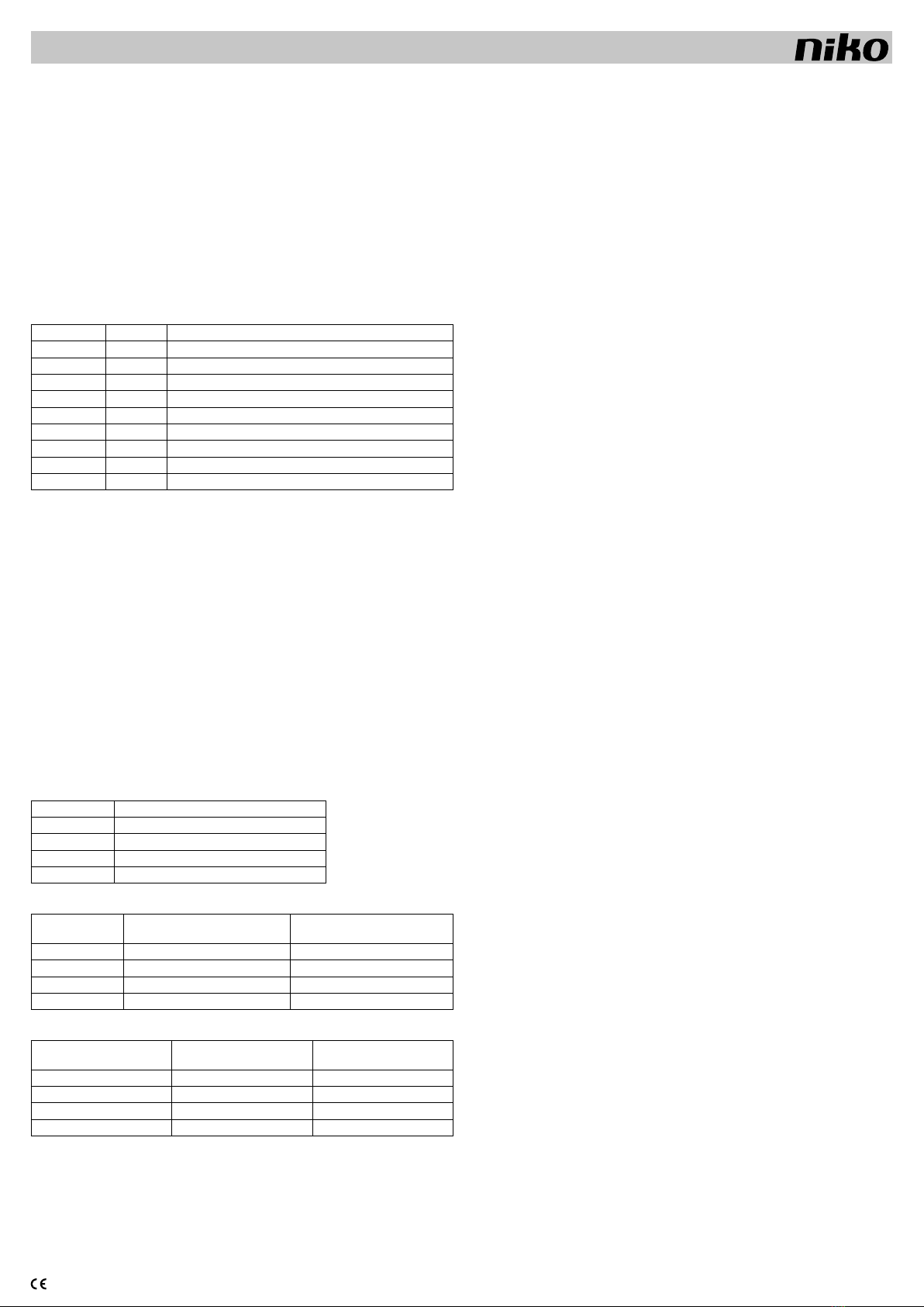
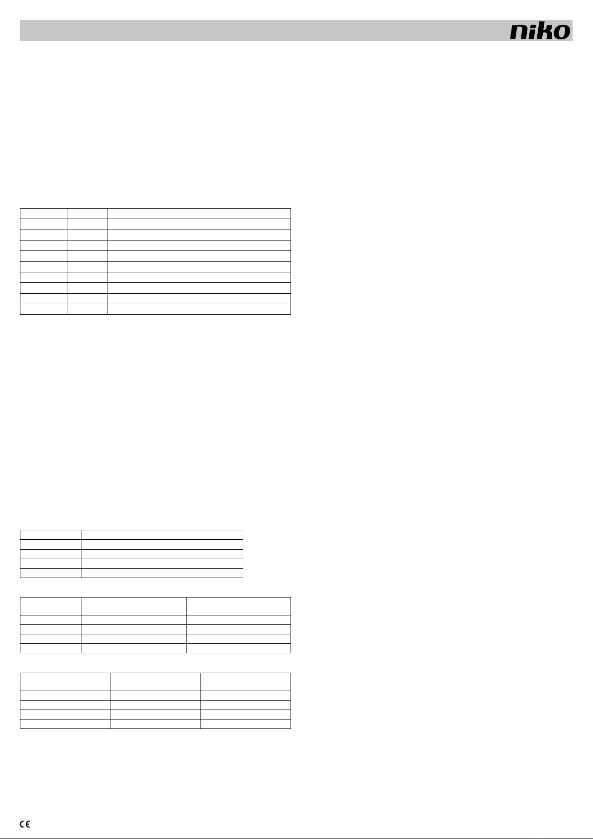
Schließen Sie die Klemmen 1 bis 7, sowie L und N gemäß anliegender Tabelle an (4 und 5 sind nicht belegt).
Klemmen nr. Symbol Funktion
1V DC+ Kleinspannungsausgang +22,5V DC (SELV)
2DALI+ Datenanschluss DALI-Bus (ELV)
3Common Gemeinsamer Anschluss für DALI und für den Spannungsausgang
4nicht belegt
5nicht belegt
6Bridge Begrenzung der Ausgangsspannung an Klemme 1 auf max. +16V DC
7Bridge Begrenzung der Ausgangsspannung an Klemme 1 auf max. +16V DC
L Phase Netzspannung 230V~ 50Hz
N Nullleiter Netzspannung 230V~ 50Hz
3.1 Verwendung als DALI-Busversorgung
Es darf nur 1 Netzteil an dem Bus angeschlossen werden (max.250mA sind als Strom auf dem DALI-Bus zugelassen).
Auf jeden Fall sollte erst kontrolliert werden,ob nicht bereits ein anderer Busteilnehmer (z.B. ein Dimmer) den Bus
versorgt. Das Netzteil wird mit dem Bus verbunden, indem eine Brücke zwischen die Klemmen 1 und 2 gelegt
wird. Diese Verbindung darf nur auf dem Netzteil und niemals auf der Montageleiterplatte gemacht werden.
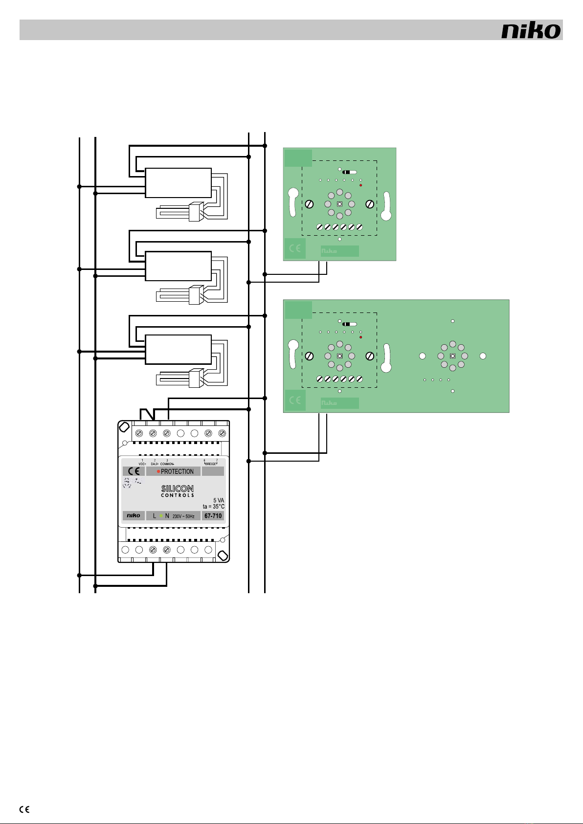
3.2 Verwendung als Hilfsversorgung
Wählen Sie die Montageleiterplatten an denen die Hilfsversorgung angeschlossen werden soll (Prozedur siehe
Gebrauchsanleitung Montageleiterplatten).Verbinden Sie Klemme 1 des Netzteils 67-710 mit der Klemme +22,5V jeder
ausgewählten Montageleiterplatte. DieseVerbindung darf nur auf dem Netzteil und niemals auf der Montageleiterplatte
gemacht werden. Schalten Sie den Schalter der entsprechenden Montageleiterplatte entsprechend um.
3.3 Verwendung als Silicon Controls Netzteil
Verbinden Sie die Silicon Controls Spannungseingänge mit den Klemmen 1 und 3.
Achtung!
EVG´s von verschiedenen Herstellern dürfen auf demselben Bus angeschlossen werden.Steuer- und Bediengeräte
von verschiedenen Herstellern dürfen nicht ohne weiteres auf demselben Bus angeschlossen werden.Es müssen
dabei 2 Parameter beachtet werden:
- Einige Hersteller verwenden keine standardisierten Steuerkodes. Es ist deshalb möglich,dass das angeschlossene
Steuerungssystem gar nicht oder nun sporadisch arbeitet.
- Einige Hersteller von Steuer- und Bediengeräten können die Maximalspannung des DALI-Busses von 22,5V
nicht verarbeiten. Hierbei ist es möglich die Versorgungsspannung des 67-710 auf max.16V zu begrenzen.
Deshalb ist es sinnvoll, die Versorgungsspannung bei den verschiedenen Steuerungssystemen vorher zu
kontrollieren.
Tabelle 1
Montageleiterplattentyp Stromverbrauch Montageleiterplatte + Bedienelement
1-fach 14 + (1 x 2) = 16mA
2-fach 14 + (2 x 2) = 18mA
3-fach 14 + (3 x 2) = 20mA
4-fach 14 + (4 x 2) = 22mA
Tabelle 2
Max. Anzahl
Montageleiterplatten
Montageleiterplatte +
Bedienelement versorgt über
DALI-Bus (1)
Montageleiterplatte +
Bedienelement versorgt über
Hilfsstromversorgung (2)
1-fach 6 14
2-fach 5 12
3-fach 5 11
4-fach 4 10
Tabelle 3
Max. Anzahl Bedienelemente Bedienelement versorgt über
DALI-Bus (1)
Bedienelement versorgt über
Hilfsstromversorgung (2)
1-fach 6 14
2-fach 10 24
3-fach 15 33
4-fach 16 40
(1) Unabhängig davon, ob das Netzteil auf 22,5V oder 16V eingestellt ist.
(2) Gilt nur, falls das Netzteil als Hilfsstromversorgung verwendet wird (separate DALI-Busverdrahtung). Falls
die Versorgung über den DALI-Bus läuft, steht nur die Hälfte des Stroms dem Steuersystem zur Verfügung.
Die andere Hälfte erhält das EVG.
- DALI-Bus und Hilfsstromversorgung können separat angeschlossen werden um die Anzahl der Bedienelemente
zu erhöhen.
- Die max. Anzahl an Bedienelementen hängt von der Konfiguration ab. Jede Niko-Montageleiterplatte hat einen
Verbrauch von 14mA, jedes Bedienelement einen Verbrauch von 2mA. Der genaue Verbrauch kann mitTabelle
1 exakt berechnet werden.
Sollten sie weitere Fragen hierzu haben, so nehmen Sie bitte mit unserer Hotline Kontakt auf.
- Dieses Netzteil erzeugt bei normalem Gebrauch eine Abwärme von max. 5W. Sorgen Sie für ausreichende
Wärmeabfuhr. Das Gerät sollte nicht mit isolierenden Materialien abgedeckt werden. Bei der Installation von
verschiedenen Geräten in einem Verteiler kann die Temperatur wesentlich über die Umgebungstemperatur hinaus
ansteigen. Dies kann die Funktion des Gerätes negativ beeinflussen (Begrenzung der max.Ausgangsleistung durch
die Übertemperatursicherung). Sorgen Sie für ausreichende Ventilation des Verteilers, sodass die Temperatur im
Verteiler nicht über 35°C ansteigt.
- Nach einem Stromausfall ist das Netzteil sofort wieder betriebsbereit.
4. WARTUNG
- Kontrollieren Sie regelmäßig, ob die Anschlussklemmen fest sitzen.
5. TECHNISCHE DATEN
- Betriebsspannung: 207 bis 253V~, Frequenz 50Hz ±1%
- Dimensionen: 54,5 x 70 x 89mm
- REG-Montage auf DIN-Schiene in geschlossenem Kleinverteiler
- Gewicht: 0,400kg
- Betriebsumgebungstemperatur: min.0°C bis max.35°C
- Nichtkondensierende Luftfeuchte
- Eigenstromverbrauch: 5W
- Max. Umgebungstemperatur ta = 35°C
- Max. Drahtquerschnitt pro Anschlussklemme: 2 x 2,5mm2
- Maximallast: 225mA
- Schutzschaltungen: Übertemperatur-, Kurzschluss- und Überlastsicherung
- Überlastsicherung wird ab 240mA aktiv
- Entspricht der Norm EN 61558-1
- Galvanische Trennung:
- SELV zwischen den Anschlussklemmen:
- 1 (V DC+) und 3 (gemeinsamer Anschluss), außer wenn am DALI-Bus angeschlossen (Brücke zwischen
Klemme 1 und 2)
- 6 und 7 (Wahl derAusgangsspannung), außer wenn am DALI-Bus angeschlossen (Brücke zwischen Klemme
1 und 2)
- Kleinspannung zwischen den Klemmen:
- 1 (VDC+) und 3 (gemeinsamer Anschluss), falls Brücke zwischen Klemme 1 und 2
- Die Klemmen 6 und 7 dienen zur Auswahl der Ausgangsspannung:
- keine Brücke zwischen den Klemmen: 22,5V DC ±0,5V
- Brücke zwischen den Klemmen: 16V DC ±0,5V
- Zur Versorgung von Silicon Controls Systemen ist die Spannung auf 22,5V einzustellen (keine Brücke)
- Als Hilfsversorgung der Niko-Montageleiterplatten für das DALI-System: 22,5V DC
- Als Netzteil der Niko-Montageleiterplatten und Bedienelemente: 22,5V DC
- Als Netzteil zur Versorgung von DALI- Komponenten anderer Hersteller:Abhängig von deren technischen Daten:
falls erforderlich 16V DC (Legen Sie eine Brücke zwischen die Klemmen 6 und 7; im Auslieferungszustand
nicht vorhanden)
- Kompatibel mit DALI gemäß EN60929 (min. 7V DC; max. 24V DC)
6. FEHLERBEHEBUNG:
Grüne LED aus: Keine Netzspannung (230V~ Versorgung unterbrochen): Kontrollieren Sie die Anschlüsse, die
zugehörige Sicherung und die anderen Schutzeinrichtungen.
Rote LED an:
- Überlastung des Busses: Zu viele Teilnehmer am DALI-Bus angeschlossen. Problemlösung:Schalten Sie einen
Teil der Montageleiterplatten mit dem entsprechenden Schalter auf Hilfsversorgung um (Vorgehensweise siehe
Gebrauchsanleitung Montageleiterplatten).
- Übertemperaturschutz:Kontrollieren Sie die Temperatur im Verteilerkasten (max.35°C). Sorgen Sie ggf.für Belüftung
oder Kühlung. Der Übertemperaturschutz wird nach dem Absinken der Temperatur automatisch zurückgesetzt.
- Ausgangskurzschlussschutz (z.B. durch Kurzschluss auf dem DALI-Bus):Kontrollieren Sie alle entsprechenden
Anschlüsse und schalten sie das Netzteil erst nach Aufhebung dieser Kurzschlüsse wieder ein.
7. GESETZLICHE BESTIMMUNGEN
- Die Installation darf ausschließlich von einem Fachmann des Elektrohandwerks unter Berücksichtigung der
geltenden Vorschriften vorgenommen werden.
- Übergeben Sie dem Benutzer diese Gebrauchsanleitung. Sie ist den Unterlagen der elektrischen Anlage bei-
zufügen und muss auch eventuellen neuen Besitzern übergeben werden. Zusätzliche Exemplare erhalten Sie
über unsere Website oder unseren Servicedienst.
- Bei der Installation müssen Sie u.a. Folgendes berücksichtigen:
- die geltenden Gesetze, Normen und Vorschriften;
- den Stand der Technik zum Zeitpunkt der Installation;
- diese Gebrauchsanleitung die im Zusammenhang mit jeder spezifischen Anlage gesehen werden muss;
- die Regeln fachmännischen Könnens.
- Sollten Sie Fragen haben, können Sie sich an die Niko-Hotline oder an eine anerkannte Kontrollstelle wenden:
Hotline Belgien: +32 3 778 90 80
Hotline Moeller Deutschland:
Berlin: +49 30 701902-46 Hamburg: +49 40 75019-281
Düsseldorf: +49 2131 317-37 Frankfurt a.M.: +49 69 50089-263
Stuttgart: +49 711 68789-51 München: +49 89 460 95-218
Mail: gebaeudeautomation@moeller.net
Österreich: Moeller Gebäudeautomation UG Schrems 0043-2853-702-0
Im Falle eines Defektes an Ihrem Niko-Produkt, können Sie dieses mit einer genauen Fehlerbeschreibung
(Anwendungsproblem, festgestellter Fehler, usw.) an Ihren Moeller- oder Niko-EGH zurückbringen.
8. GARANTIEBESTIMMUNGEN
- Garantiezeitraum: Zwei Jahre ab Lieferdatum.Als Lieferdatum gilt das Rechnungsdatum zu dem der Endkunde
das Produkt gekauft hat. Falls keine Rechnung mehr vorhanden ist, gilt das Produktionsdatum.
- Der Endkunde ist verpflichtet, Niko über den festgestellten Mangel innerhalb von zwei Monaten zu informieren.
- Im Falle eines Mangels an dem Produkt hat der Endkunde das Recht auf eine kostenlose Reparatur oder Ersatz.
Dies wird von Niko entschieden.
-Niko ist nicht für einen Mangel oder Schaden verantwortlich, der durch unsachgemäße Installation, nicht bestimmungs-
gemäßen oder unvorsichtigen Gebrauch oder falsche Bedienung oder Anpassen/Ändern des Produktes entsteht.
- Die zwingenden Vorschriften der nationalen Gesetzgebung bezüglich des Verkaufs von Konsumgütern und
der Schutz des Kunden in den Ländern in denen Niko direkt oder über seine Tochtergesellschaften, Filialen,
Distributoren, Handelsvertretungen oder Vertretern verkauft, haben Vorrang vor den obigen Bestimmungen.

nv Niko sa Industriepark West 40, BE-9100 Sint-Niklaas, Belgium — tel. +32 3 778 90 00 — fax +32 3 777 71 20 — e-mail: [email protected] — www.niko.be PM067-71000R18021
67-710
Read the complete manual before attempting installation and activating the system.
1. DESCRIPTION
Galvanically isolated power supply (SELV) for DALI bus systems,DALI auxiliary power supply (specific Niko applica-
tion) or power supply for Silicon Controls control systems. Housing for DIN rail 4 modules, standard dimensions.
Adjustable output voltage of 22,5V or 16V, 225mA.
The Niko power supply provides an output voltage in SELV (safety extra low voltage). A DALI bus only operates
on ELV (extra low voltage: basic isolation of 2,5kV).
2. OPERATION
The 67-710 power supply provides a low voltage current of 22,5V or 16V. The standard output voltage is 22,5V.
If necessary, the voltage can be limited to 16V DC by means of a bridge between terminals 6 and 7.The current
is electronically limited to a max. of 240mA according to the DALI standard. The power supply is automatically
switched over to 16V DC voltage if a power supply is already connected to the bus with a voltage of less than
19V (tolerance 0,5 V DC).
A green LED (at the bottom between L and N) indicates the presence of the 230V power supply voltage.A red LED
(next to the ‘protection’ indication) indicates that the overcurrent or thermal safety device is operating.
3. INSTALLATION
Connect all terminals from 1 to 7 (4 and 5 unused) and L and N as shown in the table below.
Terminal no. Symbol Function
1V DC+ Low voltage power supply output +22,5V DC (SELV)
2DALI+ Data connection DALI bus (ELV)
3Common Common (both for power supply and DALI bus)
4Not used
5Not used
6Bridge Power supply output on terminal limited to 1 max. +16V DC
7Bridge Power supply output on terminal limited to 1 max. +16V DC
L Phase power supply input 230V~ 50Hz
N Neutral conductor power supply input 230V~ 50Hz
3.1 Use as a DALI bus power supply
Only 1 power supply can be connected to the bus (max. 250mA current allowed on the DALI bus). First check
whether any other unit (e.g. a dimmer) is already providing the bus with power supply. The power supply is
connected to the bus by means of a bridge between terminals 1 and 2. Always make this connection on the
power supply, never on the circuit boards.
3.2 Use as an auxiliary power supply
Select the circuit boards that must be connected to the auxiliary power supply. (Procedure: see manual circuit
boards). Connect terminal 1 of the 67-710 to terminal 22,5V DC+ of each selected circuit board.Always make
this connection on the power supply and never on the circuit boards. Put the switch of the selected circuit
boards in the correct position.
3.3 Use as a Silicon Controls power supply
Connect the Silicon Controls power supply inputs to terminals 1 and 3.
ATTENTION!
Ballasts of different brands can be connected to the same bus. Controls of different brands CANNOT be connected
to the same bus just like that. Two parameters must be taken into account:
- Some manufacturers use non-standard control codes. It is therefore possible that the connected control system
will not work at all or only sporadically.
- Some control systems cannot handle the maximum voltage of the DALI bus (22.5V). It is therefore possible to
limit the power supply voltage of the 67-710 unit to max. 16V. Check the allowed power supply voltage of the
different control systems.
Table 1
Circuit board type Power consumption circuit board and control points
Simple 14 + (1 x 2) = 16mA
2-fold 14 + (2 x 2) = 18mA
3-fold 14 + (3 x 2) = 20mA
4-fold 14 + (4 x 2) = 22mA
Table 2
Max. number of
circuit boards
Circuit board + control points
supplied via DALI bus (1)
Circuit board + control points sup-
plied via auxiliary power supply (2)
Simple 6 14
2-fold 5 12
3-fold 5 11
4-fold 4 10
Table 3
Max. number of control points Control points supplied via
DALI bus (1)
Control points supplied via
auxiliary power supply (2)
Simple 6 14
2-fold 10 24
3-fold 15 33
4-fold 16 40
(1) Irrespective of whether the power supply is set to 22,5V or 16V.
(2) Can only be applied if used as auxiliary power supply (separate from DALI bus wiring). If the power supply
is connected via the DALI bus, only half of the power is available for the control systems. The other half is
reserved for the ECG.
- The DALI bus and auxiliary power supply can be connected separately in order to increase the number of control
points.
- The max. number of control points depends on the configuration. Every Niko circuit board uses 14mA. Every Niko
control point uses 2mA. The total consumption can be calculated by using table 1.
Consult Niko for further information.
- During normal operation, this power supply produces an amount of heat (max. 5W). Make sure this heat can
escape adequately. Do not cover the power supply with insulating materials.When mounting different devices in
the same enclosure, the temperature in the enclosure can exceed the ambient temperature.This can influence
the operation of the power supply (limitation of the max. capacity – thermal protection). Provide sufficient air
ventilation of the enclosure, so the temperature in the enclosure is always below 35°C.
- After a power cut, the power supply is automatically switched back on.
4. PRODUCT MAINTENANCE
- Regularly check whether the terminals are still firmly fixed.
5. TECHNICAL SPECIFICATIONS
- Operating voltage: 207 to 253V~, frequency 50Hz ±1%
- Dimensions: 54,5 x 70 x 89mm
- DIN-rail mounting: to be mounted in a closed distribution board
- Weight: 0,400kg
- Ambient temperature during operation: min. 0°C, max. 35°C
- Non-condensing atmospheric humidity
- Stand-by power: 5W
- Max. ambient temperature: ta= 35°C
- Max. cable diameter per terminal: 2 x 2,5mm2
- Max. load: 225mA
- Protection modes: thermal, overload and short-circuit protection
- Overload protection active from 240mA
- In conformity with the standard EN61558-1
- Information concerning galvanic isolation:
- SELV between connector terminals:
-1 (VDC+) and 3 (common) except when connected to DALI bus (bridge between terminals 1 and 2)
-6 and 7 (output voltage selection) except when connected to DALI bus (bridge between terminals 1 and 2)
- ELV between terminals:
-1 (VDC+) and 3 (common) if bridge between terminals 1 and 2
- Connectors 6 and 7 are used to select the nominal output voltage:
- no bridge between terminals: 22,5V DC ±0,5V
- bridge between terminals: 16V DC ±0,5V
- Set power supply for Silicon Controls systems to 22,5V DC (no bridge)
- Niko circuit boards auxiliary power supply for DALI: 22,5V DC
- Niko circuit boards and control modules power supply: 22,5V DC
- power supply of DALI components from other manufacturers: depends on the technical specifications of
the manufacturer in question: if necessary 16V DC (place a bridge between terminals 6 and 7, bridge not
included)
- Compatible with DALI according to EN60929 (min. 7V DC max. 24V DC)
6. TROUBLESHOOTING:
Green LED off: no power supply (230V~ interrupted): check the connection, the position of the circuit breakers
and other protection devices.
Red LED lights:
- Either: bus overload:too many units connected to the DALI bus. Solution:switch over some of the circuit boards
to an auxiliary power supply by means of the switch provided (procedure: see circuit boards manual).
- Or: protection against over-heating. Check the temperature in the enclosure (max. 35° C) and, if necessary,
introduce measures for ventilation and/or cooling. The temperature protection is equipped with an auto-reset,
which will be activated as soon as the temperature has cooled down sufficiently.
- Or: protection against a short-circuit on the load side (e.g. short-circuit on the DALI bus). Check the various
connections. Switch the power supply after all short-circuits have been removed only.
7. LEGAL WARNINGS
- The installation has to be carried out by a registered installer and in compliance with the statutory regulations.
- This user manual has to be handed over to the user. It has to be included in the electrical installation file and
has to be passed on to any new owners. Additional copies are available on the Niko website or via the support
service.
- During installation, the following has to be taken into account (not limited to list below):
- The statutory laws, standards and regulations;
- The state of the art technique at the moment of installation;
- This user manual, which must be read within the scope of each specific installation, only states general
regulations;
- The rules of proper workmanship
- In case of questions, you can consult Niko’s support service or contact a registered control organisation.
Support Belgium: Support UK:
+32 3 778 90 80 +44 1525877707
website : http://www.niko.be http://www.nikouk.com
In case of a defect, you can return your product to a registered Niko wholesaler, together with a clear description
of your complaint (Conditions of use, stated defect…).
8. GUARANTEE PROVISIONS
- Period of guarantee: 2 years from date of delivery. The delivery date is the invoice date of purchase of the
product by the consumer. If there is no invoice, the date of production applies.
- The consumer is obliged to inform Niko in writing about the defect, within two months after stating the
defect.
- In case of a failure to conform, the consumer has the right to a repair or replacement (decided by Niko) free of
charge.
- Niko cannot be held liable for a defect or damage as a result of an incorrect installation, improper or careless
use or wrong usage or transformation of the goods.
- The compulsory regulations of the national legislation concerning the sales of consumer goods and the protection
of the consumers in the countries where Niko sells, directly or via sister or daughter companies, chain stores,
distributors, agents or permanent sales representatives, take priority over the rules and regulations mentioned
above.

nv Niko sa Industriepark West 40, BE-9100 Sint-Niklaas, Belgium — tel. +32 3 778 90 00 — fax +32 3 777 71 20 — e-mail: [email protected] — www.niko.be PM067-71000R18021
67-710
230V~
N
DALI
L -+
DALI
67-011-PO
Pir cont.
Pir com.
22,5 VDC -
22,5 VDC +
Dali -
Dali +
DALI
67-032-PO
Pir cont.
Pir com.
22,5 VDC -
22,5 VDC +
Dali -
Dali +
67-011
67-032
HF BALLAST
DALI +
DALI -
L
N
HF BALLAST
DALI +
DALI -
L
N
HF BALLAST
DALI +
DALI -
L
N
67-710
230V ~ 50Hz
LN
VDC+ DALI+ COMMON- BRIDGE
PROTECTION
Table of contents
Languages:
Other Niko Power Supply manuals
Popular Power Supply manuals by other brands

Haslux
Haslux Sphera Exideal manual

SECO-LARM
SECO-LARM Enforcer EAP-5D1 Specification sheet

Surface Concept
Surface Concept Economy Series manual

F&G
F&G MOELLER Xcomfort CAEE-02 Assembly instructions

Phoenix Contact
Phoenix Contact QUINT4-PS/1AC/48DC/10 manual

Elektro-Automatik
Elektro-Automatik EA-PS 10000 4U manual