Niko 10-805-01 User manual

1
10-805-01
Lees de volledige handleiding vóór installatie en ingebruikname.
1. BESCHRIJVING
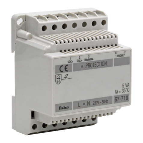
Deze gelijkspanningsvoeding wordt gebruikt voor grote audiosystemen of voor systemen
met buitenposten met video. Bij grote systemen worden ook de binnenposten met deze
voedingsmodules verbonden. De voedingsmodule is geschikt voor plaatsing in een DIN-rail
kast. De gelijkspanningsvoeding (10-805-01) werkt op de standaardnetspanning (230V~,
50Hz) en levert een gelijkspanning van 26V, 2,5A. Ze beschikt over een automatische
kortsluitings- en overbelastingsindicatie via LED (klem 36).
2. MONTAGE
Sluit de netvoeding aan op klemmen 5 en 7 van de voedingsmodule. Voor het aansluiten
van de binnen- en buitenpost(en) op de voedingsmodules, zie fig. 1 en 2. Sluit de P-ader
van de buitenpost(en) en de binnenposten aan op de gelijkspanningsvoeding. Sluit de bus
(a en b) voor de binnen- en buitenposten aan op voeding 10-801 of 10-802.
Mogelijke kabels voor de aansluiting van de binnen- en buitenpost(en) zijn:
- JYSTY(-F2) min. 3 x 2 x 0,8mm
- TVVF (-F2) min. 3 x 2 x 0,8mm
- TPVF min. 3 x 2 x 0,6mm (Beperkt het aantal aan te sluiten componenten. Voor spe-
cificaties, zie technische catalogus).
In een systeem zonder video worden niet alle paren gebruikt, maar u wordt aangeraden steeds
3 paren te voorzien om latere uitbreiding naar een videosysteem mogelijk te maken!
AUDIO
VOEDING Max. #
buitenposten*
10-801 20 20 5 2
10-801 &
10-805-01
90 90 60 > 5
tabel 1: max. aantal binnen- en buitenposten afhankelijk van de gebruikte voeding
LET OP: De max. af te leggen afstanden hangen af van de gebruikte kabel en van het aantal
buitenposten op de lijn (zie tabel 2).
NL

2
10-805-01
# buitenposten*
per lijn
max. afstand
(0,6mm)
max. afstand
(2 x 0,6mm)
max. afstand
(0,8mm)
max. afstand
(2 x 0,8mm)
1 150m 300m 250m 500m
2 80m 150m 150m 300m
> 2 beter een nieuwe lijn (bus: a en b) in ster voorzien
tabel 2: max. afstanden, afhankelijk van de diameter van de gebruikte kabel (kopergeleider)
* Een buitenpost met meer dan 20 beldrukknoppen geldt in de berekening als 2 buitenposten.
Ook een uitbreiding geldt als buitenpost!
VIDEO
Hieronder vindt u een tabel en een schema met de max. afstanden tussen de verste bin-
nenpost en de buitenpost. Tevens wordt aangegeven hoe u de posten aansluit.
200m 190m 175m 160m 150m 125m 110m 100m 90m 75m 50m
Max. afstand bij 0,6mm
5-draads
# binnenposten 1 5 20
6-draads
# binnenposten 1 4 7 13 31
Max. afstand bij 0,8mm
5-draads
# binnenposten 1 2 7 12 15 19 28 54
6-draads
# binnenposten 1 2 4 7 9 15 20 25 30 41 73
De maximale afstand, zoals hierboven weergegeven, is de afstand tussen de buitenpost
en elke binnenpost.
LET OP: de aantallen in deze tabel gelden enkel als in de installatie nergens binnenposten
parallel geprogrammeerd zijn.
NL

3
10-805-01
A B E P
12V 1A max
10-108 10-11610-116
10-525
05-540
A B E P
12V 1A max
10-505
05-540
ab PSR
230V~
Max. 180 ex.
25 26 27 28 29 30 31 32 33 34 35 36 37 38 39 40 41 42
1234567891011121314151617
43
18
44
19
45
20
46
21
47
22
48
23
49
24
3131
779955
2929 3636
26V DC / 2,5A
(Fonts)
10-805-01
+–
LNPE
123456789101112
14 15 16 17 18 19 20 21 22 23 24 25
13
AUDIO
Opmerking:
De voeding van de binnen- en buitenpost
wordt, bij gebruik van de 10-802 als bus-
voeding,verdeeld over 3 bussen.Er kunnen
max.90 binnenposten aangesloten worden.
Voor grotere audiosystemen dan hier afge-
beeld, raadpleeg de technische catalogus
of neem contact op met Niko NV.
fig.1: compleet aansluitschema met 10-801 en 10-805-01
3NL

4
10-805-01
VIDEO
Let op: sluit klem 29
(+) van de gelijkspan-
ningsvoeding niet aan
op de P-klem van de
busvoeding 10-801.
fig.2: aansluitschema met 10-801 en 10-805-01
Voor grotere videosystemen dan hier afgebeeld, moeten splitters en switchers gebruikt
worden. Uitleg hierover vindt u in de technische catalogus, u kan ook contact opnemen
met Niko NV.
NL
230V~
abEP M
abEP M
PM
aGbRPM V1 V2
16 17
LN
230V~
LN
ab + -
123456789101112
14 15 16 17 18 19 20 21 22 23 24 25
13
25 26 27 28 29 30 31 32 33 34 35 36 37 38 39 40 41 42
1234567891011121314151617
43
18
44
19
45
20
46
21
47
22
48
23
49
24
3131
779955
2929 3636
26VDC / 2,5A
(Fonts)
10-805-01
+–
LNPE
10-801 10-805-01
KV2
K
V1
V1 V2

5
10-805-01
3. WERKING EN GEBRUIK
Als de installatie correct uitgevoerd is en de installatie op het net aangesloten wordt, licht
de LED op VOEDING 20 of VOEDING 100 op. De LED aan de buitenpost licht op en verlicht
de vandaalbestendige naamplaat. Haak de hoorn van de binnenpost af om met de bezoeker
te communiceren. In geval van een systeem met video verschijnt ook het beeld van de
bezoeker op het beeldscherm. De verbinding wordt verbroken door gewoon in te haken of
automatisch na 60s.Voor meer uitleg over de werking van de binnen- en/of buitenpost(en),
raadpleeg de respectievelijke handleidingen.
LED-indicatie op de gelijkspanningsvoeding (10-805-01)
LED betekenis omschrijving
groen normale werking - De voeding volgt de normale werking.
rood overbelasting
- De uitgangsstroom van 2.5A wordt overschre-
den.
- De belasting moet gereduceerd worden.
rood
(knippert)
overschrijding van de
grens (maximale last)
en/of kortsluiting
- Overschrijding van de grens (maximale last) en/of
kortsluiting aan de secundaire kring:de 10-805-01
onderbreekt de secundaire kring.
- De 10-805-01 probeert automatisch de secundaire
kring opnieuw in te schakelen.
- Is het probleem verholpen, dan schakelt de 10-
805-01 automatisch terug aan.
4. TECHNISCHE GEGEVENS
Afmetingen: .......................8TE breed (H90 x B40 x D70mm)
Gewicht:.............................400g
Omgevingstemperatuur:......0 tot 40°C
Ingang: ..............................230V±15%, 50Hz (klemmen 1.5mm2)
Uitgang: .............................26V (Imax. 2,5A)
Opmerking: sluit de massa aan op klem 9.
5. WAARSCHUWINGEN VOOR INSTALLATIE
•
De installatie moet worden uitgevoerd door een erkend installateur en volgens de geldende
voorschriften.
•
Deze handleiding moet aan de gebruiker worden overhandigd. Het moet bij het dossier van
de elektrische installatie worden gevoegd en worden overgedragen aan eventuele nieuwe
eigenaars. Bijkomende exemplaren zijn verkrijgbaarvia de website of supportdienst vanNiko.
Op de Niko website is altijd de meest recente handleiding van het product terug te vinden.
• Tijdens de installatie moet rekening gehouden worden met (niet-limitatieve lijst):
- de geldende wetten, normen en reglementen.
NL

6
10-805-01
- de stand van de techniek op het moment van de installatie.
- deze handleiding die alleen algemene bepalingen vermeldt en moet worden gelezen
in het kader van elke specifieke installatie.
- de regels van goed vakmanschap.
Dit product voldoet aan alle toepasselijke Europese richtlijnen en verordeningen. Indien van
toepassing, vind je de EG-verklaring van overeenstemming met betrekking tot dit product
op www.niko.eu.
6. NIKO SUPPORT
Heb je twijfel? Of wil je het product omruilen in geval van een eventueel defect? Neem dan
contact op met je groothandel of de Niko supportdienst:
• België: +32 3 778 90 80
• Nederland: +31 183 64 06 60
Contactgegevensen meer informatie vind je op www.niko.euonderderubriek“Hulp en advies”.
7. GARANTIEBEPALINGEN
•
De garantietermijn bedraagt vier jaar vanaf leveringsdatum. Als leveringsdatum geldt
de factuurdatum van aankoop van het product door de consument. Als er geen factuur
voorhanden is, geldt de productiedatum.
•
De consument isverplicht Niko schriftelijk teinformeren over hetgebrek aan overeenstemming,
en dit uiterlijk binnen de twee maanden na vaststelling.
•
In geval van een gebrek aan overeenstemming heeft de consument enkel recht op
een kosteloze herstelling of vervanging van het product, wat door Niko bepaald wordt.
•
Niko is niet verantwoordelijk voor een defect of schade als gevolg van een foutieve
installatie, oneigenlijk of onachtzaam gebruik, een verkeerde bediening, transformatie van
het product, onderhoud in strijd met de onderhoudsvoorschriften of een externe oorzaak
zoals vochtschade of schade door overspanning.
•
De dwingende bepalingenin de nationale wetgeving overde verkoop van consumptiegoederen
en de bescherming van consumenten in landen waar Niko rechtstreeks of via zuster- of
dochtervennootschappen, filialen, distributeurs, agenten of vaste vertegenwoordigers
verkoopt, hebben voorrang op bovenstaande bepalingen.
Dit product mag u niet bij het ongesorteerd afval gooien. Breng uw afgedankt product naar een
containerpark of een erkend verzamelpunt. Net als producenten en importeurs speelt ook u een
belangrijke rol in de bevordering van sortering, recycling en hergebruik van afgedankte elektrische
en elektronische apparatuur. Om de ophaling en verwerking te kunnen financieren, heft de
overheid in bepaalde gevallen een recyclingbijdrage (inbegrepen in de aankoopprijs van dit product).
NL

7
10-805-01
Lisez entièrement le mode d’emploi avant toute installation et mise en service.
1. DESCRIPTION
Cette alimentation en tension continue est utilisée pour les très grands systèmes audio ou
les systèmes équipés de postes extérieurs avec écran LCD. Dans le cas de grands systèmes,
les postes intérieurs sont également raccordés avec ces modules d’alimentation. Le module
d’alimentation convient à une installation dans une armoire à rail DIN. L’alimentation en
tension continue (10-805-01) fonctionne sur la tension de réseau standard (230V~, 50Hz)
et fournit une tension continue de 26V, 2,5A. Elle possède une indication automatique de
court-circuit et de surcharge via LED (borne 36).
2. MONTAGE
Raccordez l’alimentation du réseau aux bornes 5 et 7 du module d’alimentation. Pour
raccorder le(s) poste(s) intérieur(s) et extérieur(s) aux modules d’alimentation, voir les fig.
1 et 2. Raccordez le conducteur P du / des poste(s) extérieur(s) et des postes intérieurs à
l’alimentation en tension continue. Raccordez le bus (a et b), pour les postes intérieurs et
extérieurs, sur l’alimentation 10-801 ou l’alimentation 10-802.
Câbles possibles pour le raccordement des postes intérieurs et extérieurs:
- JYSTY(-F2) min. 3 x 2 x 0,8mm
- TVVF(-F2) min. 3 x 2 x 0,8mm
- TPVF min. 3 x 2 x 0,6mm (limite le nombre d’éléments raccordables. Pour les spécifi-
cations, voir le catalogue technique).
Toutes les paires ne sont pas utilisées dans un système sans vidéo, mais nous conseillons
de prévoir quand même toujours 3 paires pour permettre l’extension vers un système
vidéo!
AUDIO
ALIMENTA-
TION
Nombre max.
de postes
extérieurs*
10-801 20 20 5 2
10-802 &
10-805-01
90 90 60 > 5
Tableau 1: le nombre max. de postes intérieurs et extérieurs dépend de l’alimentation utilisée
7FR

8
10-805-01
ATTENTION: la distance max.pouvant être parcourue dépend du câble utilisé et du nombre
de postes extérieurs sur la ligne (voir tableau 2).
Nombre de postes
extérieurs* par ligne
Distance max.
(0,6mm)
Distance max.
(2 x 0,6mm)
Distance max.
(0,8mm)
Distance max.
(2 x 0,8mm)
1 150m 300m 250m 500m
2 80m 150m 150m 300m
> 2 Il vaut mieux prévoir une nouvelle ligne (bus: a et b) en étoile.
Tableau 2: distances maximales, en fonction de la section du câble utilisé (conducteur en cuivre)
* Un poste extérieur pourvu de plus de 20 boutons de sonnerie est considéré comme 2 postes
extérieurs. Une extension est également considérée comme un poste extérieur!
VIDEO
Vous disposez ci-dessous d’un tableau et d’un schéma indiquant les distances maximales
entre le poste intérieur le plus éloigné et le poste extérieur. Il est en outre indiqué comment
raccorder les postes.
200m 190m 175m 160m 150m 125m 110m 100m 90m 75m 50m
Distance max. pour 0,6mm
5 fils
# de postes intérieurs 1 5 20
6 fils
# de postes intérieurs 1 4 7 13 31
Distance max. pour 0,8mm
5 fils
# de postes intérieurs 1 2 7 12 15 19 28 54
6 fils
# de postes
intérieurs 1 2 4 7 9 15 20 25 30 41 73
La distance maximale telle qu’exprimée ci-dessus est la distance entre le poste extérieur
et chaque poste intérieur.
ATTENTION: les chiffres indiqués dans ce tableau sont uniquement valables si l’installation
ne comprend pas de postes intérieurs programmés en parallèle.
FR

9
10-805-01
A B E P
12V 1A max
10-108 10-11610-116
10-525
05-540
A B E P
12V 1A max
10-505
05-540
ab PSR
230V~
Max. 180 ex.
25 26 27 28 29 30 31 32 33 34 35 36 37 38 39 40 41 42
1234567891011121314151617
43
18
44
19
45
20
46
21
47
22
48
23
49
24
3131
779955
2929 3636
26V DC / 2,5A
(Fonts)
10-805-01
+–
LNPE
123456789101112
14 15 16 17 18 19 20 21 22 23 24 25
13
AUDIO
Remarque:
L’alimentation du poste intérieur et extérieur,
lorsdel’alimentation 10-802 comme alimen-
tation bus, partagée sur 3 bus. 90 postes
intérieurs max.peuvent être raccordés. Pour
de plus grands systèmes audio que ceux
illustrés ici,consultez le catalogue technique
ou contactez Niko SA.
fig.1: schéma de raccordement complet avec 10-801 et 10-805-01
FR

10
10-805-01
VIDEO
Attention: ne raccor-
dez pas borne 29 (+)de
l’alimentation en ten-
sion continue au borne
P de l’alimentation bus
10-801.
fig.2: schéma de raccordement avec 10-801 et 10-805-01
Pour de plus grands systèmes vidéo que ceux illustrés ici, des répartiteurs et des sélecteurs
doivent être utilisés. Pour de plus amples informations, consultez le catalogue technique
ou contactez Niko SA.
FR
230V~
abEP M
abEP M
PM
aGbRPM V1 V2
16 17
LN
230V~
LN
ab + -
123456789101112
14 15 16 17 18 19 20 21 22 23 24 25
13
25 26 27 28 29 30 31 32 33 34 35 36 37 38 39 40 41 42
1234567891011121314151617
43
18
44
19
45
20
46
21
47
22
48
23
49
24
3131
779955
2929 3636
26VDC / 2,5A
(Fonts)
10-805-01
+–
LNPE
10-801 10-805-01
KV2
K
V1
V1 V2

11
10-805-01
3. FONCTIONNEMENT ET UTILISATION
Si l’installation a été correctement réalisée et a été raccordée au réseau, la LED s’allume
sur l’alimentation 20 ou l’alimentation 100. La LED du poste extérieur s’allume également et
éclaire la plaque nominative antivandalisme. Décrochez le combiné pour communiquer avec
le visiteur. Dans le cas d’un système avec vidéo, l’image du visiteur apparaîtra également à
l’écran.La communication est interrompue en raccrochant simplement ou automatiquement
après 60s. Pour de plus amples explications à propos du fonctionnement des postes intérieurs
et/ou extérieurs, consultez les modes d’emploi respectifs.
Indication LED sur l’alimentation en tension continue (10-805-01)
LED signification description
vert fonctionnement
normal
- L’alimentation suit le fonctionnement normal.
rouge surcharge - Le courant de sortie de 2,5A est dépassé.
- La charge doit être réduite.
rouge
(clignote)
dépassement de la
limite (charge max.)
et/ou court-circuit
- Dépassement de la limite (charge max.) et/ou court-
circuit au circuit secondaire: la 10-805-01 coupe
le circuit secondaire.
- La 10-805-01 essaie de remettre automatiquement
sous tension le circuit secondaire.
- Si le problème est résolu, la 10-805-01 se réen-
clenche automatiquement.
4. CARACTERISTIQUES TECHNIQUES
Dimensions: .......................8U de large (H 90 x l 105 x P 70 mm)
Poids:.................................400g
Température ambiante:........de 0 à 40°C
Entrée: ..............................230V±15%, 50Hz (bornes 1,5mm2)
Sortie: ...............................26V (Imax. 2,5A)
Remarque: raccorder la masse à la borne 9
5. MISES EN GARDE CONCERNANT L‘INSTALLATION
•
L’installation doit être effectuée par un installateur agréé et dans le respect des
prescriptions en vigueur.
•
Ce mode d’emploi doit être remis à l’utilisateur. Il doit être joint au dossier de l’installation
électrique et être remis aux nouveaux propriétaires éventuels. Des exemplaires
supplémentaires peuvent êtreobtenus sur le site webouauprès du service supportde Niko.
• Il y a lieu de tenir compte des points suivants pendant l’installation (liste non limitative):
- les lois, les normes et les réglementations en vigueur.
- l’état de la technique au moment de l’installation.
FR

12
10-805-01
- ce mode d’emploi qui stipule uniquement des dispositions générales et doit être lu
dans le cadre de toute installation spécifique.
- les règles de l’art.
Ce produit est conforme à l’ensemble des directives et règlements européens applicables.
Le cas échéant, vous trouverez la déclaration CE de conformité relative à ce produit sur
le site www.niko.eu.
6. SUPPORT DE NIKO
En cas de doute ou si vous voulez échanger le produit en cas de défaut éventuel, veuillez
prendre contact avec votre grossiste ou avec le service support de Niko:
• Belgique: +32 3 778 90 80 • France: +33 820 20 66 25
Vous trouverez les coordonnées et de plus amples informations sur le site www.niko.eu,
sous la rubrique “Aide et conseils”.
7. DISPOSITIONS DE GARANTIE
• Le délai de garantie est de quatre ans à partir de la date de livraison. La date de la
facture d’achat par le consommateur est considérée comme la date de livraison. En
l’absence de facture, la date de fabrication est valable.
• Le consommateur est tenu de prévenir Niko par écrit de tout défaut de conformité,
dans un délai maximum de deux mois après constatation.
•
En cas de défaut de conformité, le consommateur peut uniquement prétendre à la
réparation gratuite ou au remplacement gratuit du produit, selon l’avis de Niko.
•
Niko ne peut être tenu pour responsable d’un défaut ou de dégâts résultant d’une
installation fautive, d’une utilisation impropre ou négligente, d’une commande erronée,
d’une transformation du produit, d’un entretien contraire aux consignes d’entretien ou
d’une cause externe telle que de l’humidité ou une surtension.
•
Les dispositions contraignantes de la législation nationale ayant trait à la vente de
biens de consommation et à la protection des consommateurs des différents pays où
Niko procède à la vente directe ou par l’intermédiaire d’entreprises sœurs, de filiales,
de succursales, de distributeurs, d’agents ou de représentants fixes, prévalent sur les
dispositions susmentionnées.
Ce produit ne peut pas être jeté avec les déchets non triés.Apportez vos équipements obsolètes
électriques et électroniques à un point de collecte agréé. Tout comme les producteurs et
importateurs, vous jouez un rôle important dans le triage, le recyclage et la réutilisation des
appareils électriques et électroniques. Afin de pouvoir financer la collecte et le traitement
écologique, les autorités imposent dans certains cas une cotisation de recyclage (comprise dans le prix
d’achat de ce produit).
FR
EMBALLAGES
CARTONS ET PAPIER
À TRIER

13
10-805-01
Read the complete manual before attempting installation and activating the
system.
1. DESCRIPTION
This DC power supply is used for larger audio systems or for systems with external units
with video. In case of large systems, the internal units are also connected to this power
supply module.The power supply module is suitable for mounting in a DIN-rail cabinet. The
DC power supply (10-805-01) operates on the mains voltage (230V~, 50Hz) and provides a
DC power of 26V, 2.5A. The DC power supply is provided with a short circuit and overload
indication via LED (terminal 36).
2. INSTALLATION
Connect the mains supply to terminals 5 and 7 of the power supply module. For how to
connect the internal and external unit(s) to the power supply module, see fig.1 and 2.Connect
the P-wire of the external and internal units to the DC power supply. Connect the bus (a and
b) for the internal and external units to power supply 10-801 or 10-802.
Possible cables for connecting the internal and external unit(s) are:
- JYSTY(-F2) min. 3 x 2 x 0,8mm
- TVVF (-F2) min. 3 x 2 x 0,8mm
- TPVF min. 3 x 2 x 0,6mm (Limits the number of components to be connected. For
specifications, see technical catalogue).
Not all of the pairs are used in a system without video, yet we recommend to always
provide 3 pairs in order to allow future extension to a video system!
AUDIO
POWER
SUPPLY
max. # external
units*
10-801 20 20 5 2
10-801 &
10-805-01
90 90 60 > 5
table 1: max. number of internal and external units depending on the power supply used
NOTE: The max. distance to be covered depends on the cable used and the number of
external units on the line (see table 2).
EN

14
10-805-01
# external units*
per line
max. distance
(0,6mm)
max. distance
(2 x 0,6mm)
max. distance
(0,8mm)
max. distance
(2 x 0,8mm)
1 150m 300m 250m 500m
2 80m 150m 150m 300m
> 2 provide a new line (bus: a and b) in star
table 2: max. distances depending on the diameter of the cable used (copper conductor)
* An external unit with over 20 bell push buttons is considered 2 external units.An extension
is also considered an external unit!
VIDEO
A table and a diagram with the max. distances between the farthest internal unit and the
external unit is given below. It also shows how to connect the units.
200m 190m 175m 160m 150m 125m 110m 100m 90m 75m 50m
Max. distance at 0,6mm
5-wire
# internal units 1 5 20
6-wire
# internal units 1 4 7 13 31
Max. distance at 0,8mm
5-wire
# internal units 1 2 7 12 15 19 28 54
6-wire
# internal units 1 2 4 7 9 15 20 25 30 41 73
The max. distance, as stated in the table above, is the distance between the external unit
and every internal unit.
NOTE: the numbers in this table only apply insofar as no internal units are programmed
in parallel within the system!
EN

15
10-805-01
A B E P
12V 1A max
10-108 10-11610-116
10-525
05-540
A B E P
12V 1A max
10-505
05-540
ab PSR
230V~
Max. 180 ex.
25 26 27 28 29 30 31 32 33 34 35 36 37 38 39 40 41 42
1234567891011121314151617
43
18
44
19
45
20
46
21
47
22
48
23
49
24
3131
779955
2929 3636
26V DC / 2,5A
(Fonts)
10-805-01
+–
LNPE
123456789101112
14 15 16 17 18 19 20 21 22 23 24 25
13
AUDIO
Note:
Whenusing the 10-802 as bus power supply,
the power supply of the internal and external
unit is distributed over 3 buses.A max. of 90
internalunitscanbeconnected.Forlargerau-
dio systems than those shown here,consult
the technical catalogue or contact Niko NV.
fig.1: complete wiring diagram with 10-801 and 10-805-01
EN

16
10-805-01
VIDEO
Attention: do not con-
nect terminal 29 (+) of
the DC power supply to
terminal P of the bus
power supply 10-801.
fig.2: wiring diagram with 10-801 and 10-805-01
For larger video systems than the ones shown here, splitters and switchers are required.
For more details, consult the technical catalogue or contact Niko NV.
EN
230V~
abEP M
abEP M
PM
aGbRPM V1 V2
16 17
LN
230V~
LN
ab + -
123456789101112
14 15 16 17 18 19 20 21 22 23 24 25
13
25 26 27 28 29 30 31 32 33 34 35 36 37 38 39 40 41 42
1234567891011121314151617
43
18
44
19
45
20
46
21
47
22
48
23
49
24
3131
779955
2929 3636
26VDC / 2,5A
(Fonts)
10-805-01
+–
LNPE
10-801 10-805-01
KV2
K
V1
V1 V2

17
10-805-01
3. OPERATION AND USE
If the installation has been carried out correctly and is connected to the mains, the LED
on POWER SUPPLY 20 or POWER SUPPLY 100 lights. The LED on the external unit lights,
thereby illuminating the vandalproof name plate. Pick up the receiver of the internal unit to
communicate with your visitor. In case of a system with video,the image of the visitor is also
displayed.The connection is wound up simply by putting the receiver down or automatically
after 60s. For details concerning the operation of the internal and/or external unit(s), consult
the corresponding user manuals.
LED indication on the DC power supply (10-805-01)
LED meaning description
green normal operation - The power supply operates normally.
red overload - The output current of 2.5A is exceeded.
- The load has to be reduced.
red
(blinking)
limit (max. load) ex-
ceeded and/or short
circuit
- Limit (max. load) exceeded and/or short circuit on
secundary circuit: the 10-805-01 interrupts the
secundary circuit.
- The 10-805-01 automatically tries to again switch
on the secundary circuit.
- If the problem is rectified, the 10-805-01 automa-
tically switches back on.
4. TECHNICAL DATA
Dimensions: .......................8U wide (H90 x W40 x D70mm)
Weight:...............................400g
Ambient temperature:..........0 to 40°C
Input: ................................230V±15%, 50Hz (terminals 1.5mm2)
Output: ..............................26V (Imax. 2,5A)
Note: connect the mass to terminal 9.
5. WARNINGS REGARDING INSTALLATION
• The installation should be carried out by a registered installer and in compliance with
the statutory regulations.
• This user manual should be presented to the user. It should be included in the electrical
installation file, and it should be passed on to any new owners. Additional copies are
available on the Niko website or via the Niko support service.
• During installation, the following should be taken into account (non-exhaustive list):
- the statutory laws, standards and regulations.
- the technology currently available at the time of installation.
EN

18
10-805-01
- this user manual, which only states general regulations and should therefore be read
within the scope of each specific installation.
- the rules of proper workmanship.
Thisproductcomplieswithallofthe relevant Europeanguidelinesandregulations.If applicable,
you can find the EC declaration of conformity regarding this product at www.niko.eu.
6. NIKO SUPPORT
In case of doubt or for the specific exchange procedure in case of a possible defect, contact
the Niko support service in Belgium at +32 3 778 90 80 or your wholesaler/installer. Contact
details and more information can be found at www.niko.eu under the“Help and advice” section.
7. GUARANTEE PROVISIONS
• The period of guarantee is four years from the date of delivery. The delivery date is
the invoice date of purchase of the product by the consumer. If there is no invoice, the
date of production applies.
• The consumer is obliged to inform Niko in writing about the non-conformity, within two
months after stating the defect.
• In case of a non-conformity, the consumer only has the right to a product repair or
replacement free of charge, which shall be decided by Niko.
• Niko shall not be held liable for a defect or damage resulting from incorrect installation,
improper or careless use, incorrect operation, transformation of the product, maintenance
that does not adhere to the maintenance instructions or an external cause, such as
damage due to moisture or overvoltage.
• The compulsory regulations of the national legislation concerning the sale of consumer
goods and the protection of the consumer in the countries where Niko sells, directly
or via sister companies, subsidiaries, chain stores, distributors, agents or permanent
sales representatives, take priority over the above-mentioned rules and regulations.
Do not dump this product with the unsorted waste. Bring it to a recognised waste collection
point.Together with producers and importers, you have an important role to play in the advancement
of sorting, recycling and reusing discarded electrical and electronic appliances.In order to finance
the waste collection and processing, the government levies a recycling contribution in some
cases (included in the purchase price of this product).
EN

19
10-805-01
Pred vykonaním inštalácie a aktivácie systému si prečítajte celý návod.
1. OPIS
Toto DC napájanie je určené pre väčšie zvukové systémy alebo pre systémy s externými
jednotkami s videom.V prípade veľkých systémov sa k tomuto napájaciemu modulu pripájajú
aj interné jednotky. Napájací modul je vhodný pre montáž na DIN lištu. DC napájací zdroj
(10-805-01) pracuje pri sieťovom napätí (230 V~, 50 Hz) a poskytuje DC napájanie 26V,
2,5A.DC napájanie je vybavené LED kontrolkou pre indikáciu skratu a preťaženia (svorka 36).
2. MONTÁŽ
Pripojte sieťové napájanie na svorky 5 a 7 napájacieho modulu. Pre návod, ako pripojiť
vnútorné a vonkajšie jednotky k napájaciemu zdroju, viď. obr. 1 a 2. Pripojte P-vodiče
vonkajších a vnútorných jednotiek na DC napájací zdroj. Pripojte zbernicu (a a b) pre interné
a externé jednotky k napájaciemu zdroju 10-801 alebo 10-802.
Na pripojenie interných a externých jednotiek je možné použiť tieto káble:
- JYSTY(-F2) min. 3 x 2 x 0,8mm
- TVVF (-F2) min. 3 x 2 x 0,8mm
- TPVF min. 3 x 2 x 0,6mm (Obmedzuje počet komponentov, ktoré je možné pripojiť.)
Technické údaje nájdete v technickom katalógu).
V systéme bez videa sa nepoužívajú všetky páry, ale odporúčame vždy pripraviť 3 páry,
aby bolo v budúcnosti možné rozšírenie na video systém!
AUDIO
NAPÁJANIE
max. #
externých
jednotiek*
10-801 20 20 5 2
10-801 &
10-805-01
90 90 60 > 5
tabuľka č. 1: max. počet interných a externých jednotiek v závislosti od použitého
napájacieho zdroja
POZNÁMKA: Max. vzdialenosť, ktorú treba prekonať, závisí od použitého kábla a počtu
externých jednotiek na linke (pozri tabuľku 2).
SK

20
10-805-01
# vonkajších jedno-
tiek * na linku
max.
vzdialenosť
(0,6mm)
max.
vzdialenosť
(2 x 0,6mm)
max.
vzdialenosť
(0,8 mm)
max.
vzdialenosť
(2 x 0,8 mm)
1 150m 300m 250m 500m
2 80m 150m 150m 300m
> 2 zabezpečte novú linku (zbernicu: a a b) v hviezdicovej topológii
tabuľka č. 2: max. vzdialenosti v závislosti od priemeru použitého kábla (medený vodič)
* Externá jednotka s viac než 20 tlačidlami zvončeka je považovaná za 2 externé jednotky.
Rozšírenie sa tiež považuje za externú jednotku!
VIDEO
Tabuľka a diagram s max. vzdialenosťami medzi najvzdialenejšou vnútornou a vonkajšou
jednotkou je uvedený nižšie. Nájdete v nich aj to, ako pripojiť jednotky.
200m 190m 175m 160m 150m 125m 110m 100m 90m 75m 50m
Max. vzdialenosť pri 0,6mm
5-vodičový
# interné jednotky 1 5 20
6 vodiče
# interné jednotky 1 4 7 13 31
Max. vzdialenosť pri 0,8 mm
5-vodičový
# interné jednotky 1 2 7 12 15 19 28 54
6 vodiče
#
interné
jednotky 1 2 4 7 9 15 20 25 30 41 73
Max.vzdialenosť, ktorá je uvedená v tabuľke vyššie,je vzdialenosť medzi externou jednotkou
a každou internou jednotkou.
POZN.: čísla v tejto tabuľke platia len v prípade, že v systéme nie sú žiadne interné
jednotky naprogramované paralelne!
SK
Table of contents
Languages:
Other Niko Power Supply manuals
Popular Power Supply manuals by other brands

Pulsar
Pulsar HPSBB 0324 27.6V/3A/2x7Ah quick start guide

Moxa Technologies
Moxa Technologies DRP-240 Series Hardware installation guide

VOLTCRAFT
VOLTCRAFT SNPS-90 operating instructions

Pts
Pts E-Kit PRC-117F user guide

Rockwell Automation
Rockwell Automation Allen-Bradley 1606-XLE480ERZ installation instructions

Ultra Products
Ultra Products X-Finity Specification sheet