Cosel KLEA120F User manual

KL-6
Basic Characteristics Data
*1The value of input current is at ACIN 115V and 100%.
*2
Burst operation at light loading, frequency is change by use condition.
Please contact us about detail.
Basic Characteristics Data
Model Circuit method
Switching
frequency
[KLz]
Input
current
[A]
*
1
Rated
input fuse
Inrush
current
protection
circuit
PCB/Pattern
Series/Parallel
operation availability
Material
Single
sided Double
sided Series
operation Parallel
operation
KLEA120F
KLNA120F
Active filter 40 - 160 1.2 250V 4A Thermistor FR-4 Yes Yes No
Flyback converter 20 - 150
*
2
KLEA240F
KLNA240F
Active filter 50 - 70 2.4 250V 8A Thermistor FR-4 Yes Yes No
Forward converter 130

1 Terminal Blocks KL-8
2 Functions KL-9
2.1 Input Voltage Range
2.2 Inrush Current Limiting
2.3 Overcurrent Protection
2.4 Overvoltage Protection
2.5 Output Ripple and Ripple Noise
2.6 Output Voltage Adjustment Range
2.7 Isolation
2.8 Signal Output
3 Series/Parallel Operation KL-10
4 Assembling and Installation Method KL-10
KL-9
KL-9
KL-9
KL-9
KL-9
KL-9
KL-9
KL-9
3.1 Series Operation
3.2 Parallel Operation
4.1 Installation Mounting methods
4.2 Derating curve depend on input voltage
4.3 Derating curve depend on ambient temperature
4.4 Derating for low temperature start-up
4.5 Life Expectancy and Warranty
4.6 Applicable Electric Cable
4.7 Others
KL-10
KL-10
KL-10
KL-11
KL-11
KL-12
KL-12
KL-13
KL-13
5 Option KL-13
5.1 Outline of option KL-13
AC-DC Power Supplies DIN Rail Type
Instruction Manual
KL-7

1 Terminal Blocks
AC-DC Power Supplies DIN Rail Type Instruction Manual
KL-8
¿ KLEA240F
¿ KLEA120F
¿ KLNA240F
¿ KLNA120F
Terminal
Number
Terminal
Name Function
1PE Protective earth Terminal
2AC (N) Input Terminals
3AC (L)
4+VOUT +Output Terminals
5
-
VOUT
-
Output Terminals
6DC_OK LED for output voltage conrmation
7TRM Adjustment of output voltage
45
6
7
123
45
6
7
123
45
6
7
123
45
6
7
123
KL-8

2.1 Input Voltage Range
¡Input voltage range of the power supplies is from AC85V to
AC264V.
¡To comply with safety standards, input voltage range is AC100-
AC240V (50/60Hz).
¡If input value doesn’t fall within above range, a unit may not oper-
ate in accordance with specications and/or start hunting or oper-
ate protection circuit or fail.
If you need to apply a square waveform input voltage, which is
commonly used in UPS and inverters, please contact us.
¡When the input voltage changes suddenly, the output voltage
accuracy might exceed the specication. Please contact us.
¡When the power supply is used with DC voltage input, an external
DC fuse is required for protection. Consult us for more details.
¡If the input voltage is more than AC250V, power factor correction
does not work and the power factor deteriorates. Consult us for
more details. (except KLEA240F, KLNA240F)
¡Operation stop voltage is set at a lower value than of a standard
version (derating is needed).
-Use Conditions
Output
KLEA120F,KLNA120F 70W
KLEA240F,KLNA240F 100W
Input AC50V or DC70V
Duty 1s/30s
*Please avoid using continuously for more than 1 second under
above conditions. Doing so may cause a failure.
2.2 Inrush Current Limiting
¡An inrush current limiting circuit is built-in.
¡If you need to use a switch on the input side, please select one
that can withstand an input inrush current.
¡Thermistor is used in the inrush current limiting circuit. When you
turn the power ON/OFF repeatedly within a short period of time,
please have enough intervals so that a power supply cools down
before being turned on.
2.3 Overcurrent Protection
¡A overcurrent protection circuit is built-in and activated over 105%
of the rated current. A unit automatically recovers when a fault
condition is removed. Please do not use a unit in short circuit and/
or under an overcurrent condition.
¡Hiccup Operation Mode (except KLEA240F, KLNA240F)
When the overcurrent protection circuit is activated and the output
voltage drops to a certain extent, the output becomes hiccup so
that the average current will also decrease.
2 Functions 2.4 Overvoltage Protection
¡An overvoltage protection circuit is built-in. If the overvoltage pro-
tection circuit is activated, shut down the input voltage, wait more
than 3 minutes and turn on the AC input again to recover the out-
put voltage. Recovery time varies depending on such factors as
input voltage value at the time of the operation.
Note :
Please avoid applying a voltage exceeding the rated voltage to an
output terminal. Doing so may cause a power supply to malfunc-
tion or fail. If you cannot avoid doing so, for example, if you need
to operate a motor, etc., please install an external diode on the
output terminal to protect the unit.
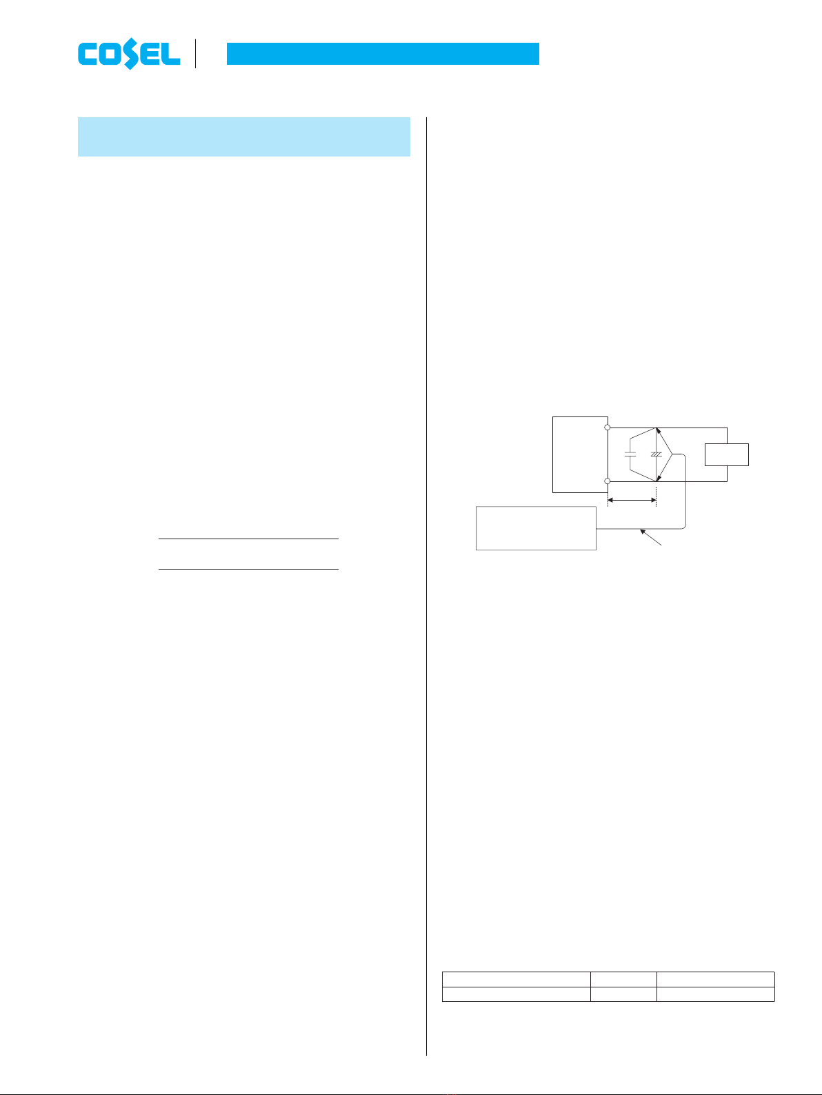
2.5 Output ripple and ripple noise
¡Output ripple noise may be inuenced by measurement environ-
ment, measuring method g 2.1 is recommended.
+Vout
-Vout
150mm
C
2
C
1
+Load
Osiloscope/
Ripple noise meter
Bw:20MHz Differential probe
C
1
:Film capacitor 0.1mF
C
2
:Aluminum electrolytic capacitor 22 mF
Fig.2.1 Measuring method of Ripple and Ripple Noise
2.6 Output Voltage Adjustment Range
¡To increase an output voltage, turn a built-in potentiometer clock-
wise. To decrease the output voltage, turn it counterclockwise.
2.7 Isolation
¡When you run a Hi-Pot test as receiving inspection, gradually
increase the voltage to start. When you shut down, decrease the
voltage gradually by using a dial. Please avoid a Hi-Pot tester with
a timer because, when the timer is turned ON or OFF, it may gen-
erate a voltage a few times higher than the applied voltage.
2.8 Signal Output
Functions of LED indicators.
¡Functions of LED indicators and signal output in the form of are
shown below. Checking the presence/absence of voltage at the
output terminal of a power supply is possible.
Table 2.1 Description of the signal output
Signal Output Normal Output is decreasing
DC_OK (LED: Green) ON OFF
AC-DC Power Supplies DIN Rail Type Instruction Manual
KL-9KL-9

3 Series/Parallel
Operation
3.1 Series Operation
¡You can use a power supply in series operation. The output cur-
rent in series operation should be lower than the rated current of a
power supply with the lowest rated current among the power sup-
plies that are serially connected. Please make sure that no current
exceeding the rated current ows into a power supply.
Load
(a)(b)
Load Load
Power
Supply
+
-
Power
Supply
+
-
Power
Supply
+
-
+
-
Power
Supply
Fig.3.1 Examples of connecting in series operation
3.2 Parallel Operation
¡There is no current balance function.
When operating in parallel, such as diode-OR, please use on the
output voltage was adjusted enough to balance the current.
Exceeds the rated output current, the output is shut down.
¡Redundancy operation is available by wiring as shown below.
I2
I1I3
-
+
+
-
Load
Power
Supply
Power
Supply
Fig.3.2 Example of connecting in redundancy operation
Even a slight difference in output voltage can affect the balance
between the values of I1and I2.
Please make sure that the value of l3 does not exceed the rated
current of a power supply.
l3[rated current value
4 Assembling and
Installation Method
4.1 Installation Mounting methods
¡About DIN-Rail
Attachment available with DIN EN60715 TH 35 (35×7.5mm or
35×15mm) (Top hat shaped DIN rail)
¡Below shows mounting orientation.
If install other then standard mounting orientation (A), please x
the power supply for withstand the impact and vibration.
(A) Standard (B) (C)
(D (E))
DIN rail
OUTPUT
INPUT OUTPUT
OUTPUT
INPUT
INPUT
OUTPUT OUTPUTINPU INT PUT
Fig.4.1 Mounting orientation
¡When you mount a power supply on a DIN rail, have the area
marked A catch one side of the rail and push the unit to the direc-
tion of B. To remove the power supply from the rail, either push
down the area marked C or insert a tool such as driver to the area
marked D and pull the unit apart from the rail.
When you couldn’t remove the unit easily, push down the area
marked C while lightly pushing the unit to the direction of E.
A
B
D
C
E
Fig.4.2 Installation method
AC-DC Power Supplies DIN Rail Type Instruction Manual
KL-10KL-10

¡Shown below the notes about installation clearance of a unit.
1Installation clearance at above and below the unit.
Please have clearance of at least 25mm above and below the
unit to avoid heat accumulation.
2Installation clearance at the side of the unit.
Please have clearance of at least 15mm side the unit to avoid
interfering with heat radiation from housing. However, refer to
Table 4.1, if adjacent device of the unit (including power supply) is
a heat source.
1
Convection
Convection
225mm
or more
1
25mm
or more
Fig.4.3 Installation clearance
Table 4.1 Installation clearance at the side of the unit.
No. Model Adjacent device of the unit
Non-heat source Heat source(*)
1 KLEA120F, KLNA120F 15mm or more 25mm or more
2 KLEA240F, KLNA240F 15mm or more 25mm or more
*Reference value when same power units are adjacent.
4.2 Derating curve depend on input voltage
¡Derating curve depend on input voltage.
Derating curve depend on input voltage is shown in Fig.4.4.
[ACV]
85 100
80
100
Load Factor
[%]
Fig.4.4 Derating curve depend on input voltage
4.3
Derating curve depend on ambient temperature
¡The operative ambient temperature as different by input voltage.
Derating curve is shown below.
¡In the hatched area,the specication of Ripple,Ripple Noise is dif-
ferent from other area.
¡Derating Curve (Convection)
¿ KLEA120F, KLNA120F
60
40
0
100
80
10
30
20
-30
0
60 70 8020 30 40 4525 6550-20-10
(A)
(B)(C)(D), (E)
Ambient Temperature [C]
Load factor [%]
Vin=AC85V - 170V*
*Derating curve depend on input voltage is required.
Fig.4.5 Derating curve depend on ambient temperature
0
100
8
70
0
30
20
60
40
(A)(B)(C)(D), (E)
55
Ambient Temperature [C]
Load factor [%]
Vin=AC170V-264V
010
-3060708020 30 40 45 6550-20-10
Fig.4.6 Derating curve depend on ambient temperature
¿ KLEA240F, KLNA240F
60
40
100
80
20
0
(A)
(B)(C)(D), (E)
*
Ambient Temperature [C]
Load factor [%]
Vin=AC85V - 170V
15
010
-3060708020 30 40 45 6550-20-10
*Derating curve depend on input voltage is required.
Fig.4.7 Derating curve depend on ambient temperature
0
100
80
20
60
40
(A)(B)(C)(D), (E)
3525
Ambient Temperature[C]
Load factor [%]
Vin=AC170V-264V
55
010
-3060708020 30 40 6550-20-10
Fig.4.8 Derating curve depend on ambient temperature
AC-DC Power Supplies DIN Rail Type Instruction Manual
KL-11KL-11

¡Ambient temperature indicates the temperature of the inlet of the air.
Ambient temperature
measurement point
Airflow
Fig.4.9 Ambient temperature measurement point
¿ KLEA120F, KLNA120F
100
80
60
40
30
20
0
V
(A) - (E)
Ambient Temperature [C]
Load factor [%]
-30-20 -100 10 20 30 40 50 60 70 80
Vin=AC85V - 264V
Forced air
Fig.4.10 Derating curve depend on ambient temperature
¿ KLEA240F, KLNA240F
100
80
60
40
20
0
(A) - (E)
Ambient Temperature [C]
Load factor [%]
-30-20 -100 10 20 304050607080
Vin=AC85V - 264V
Forced air
Fig.4.11 Derating curve depend on ambient temperature
¡Temperature of Forced air
Use the temperature measurement point as shown in Fig 4.12.
Please use at the temperature does not exceed the values in
Table 4.2.
Please also make sure that the ambient temperature does not ex-
ceed 70C.
Temperature
measureing point
Airflow
Airflow
Fig.4.12 Temperature measurement point (Forced air)
Table 4.2 Specied temperature of the measurement point
No. Model temperature measurement point
1 KLEA120F, KLNA120F 75C
2 KLEA240F, KLNA240F 75C
4.4 Derating for low temperature start-up
¡Derating shown in Table 4.3 is required for low temperature start-
up.
Table 4.3 Derating for low temperature start-up
No. Model temperature range Load factor
1 KLEA120F, KLNA120F -40Cto -20C75%
2 KLEA240F, KLNA240F
4.5 Life Expectancy and warranty
Please note derating curve depend on input voltage is required.
¡Life Expectancy
Table 4.4 Life Expectancy (KLEA120F, KLNA120F)
Mounting
method
Cooling
method
Input
voltage
Average ambient
temperature (year)
Life Expectancy
Load factor
Io[75%
Load factor
75%<Io[100%
A
Convection
AC85 - 170V
Ta = 40Cor less
10years or more 6years
Ta = 50C
5years 3years
AC170 - 264V
Ta = 45Cor less
9years 6years
Ta = 55C
4years 3years
B
Convection
AC85 - 170V
Ta = 35Cor less
10years or more 7years
Ta = 45C
5years 3years
AC170 - 264V
Ta = 40Cor less
10years or more 8years
Ta = 50C
5years 4years
C
Convection
AC85 - 170V
Ta = 20Cor less
10years or more 10years or more
Ta = 30C
10years or more 7years
AC170 - 264V
Ta = 35Cor less
10years or more 7years
Ta = 45C
6years 4years
D and E
Convection
AC85 - 170V
Ta = 15Cor less
10years or more 6years
Ta = 25C
7years 3years
AC170 - 264V
Ta = 30Cor less
10years or more 5years
Ta = 40C
5years 2years
A,B,C,D
and E Forced air
AC85 - 264V
Ta = 70C
5years 3years
Table 4.5 Life Expectancy (KLEA240F, KLNA240F)
Mounting
method
Cooling
method
Input
voltage
Average ambient
temperature (year)
Life Expectancy
Load factor
Io[75%
Load factor
75%<Io[100%
A
Convection
AC85 - 170V
Ta = 35Cor less
8years 5years
Ta = 45C
4years 2years
AC170 - 264V
Ta = 40Cor less
8years 6years
Ta = 50C
4years 3years
B
Convection
AC85 - 170V
Ta = 20Cor less
10years or more 7years
Ta = 30C
6years 3years
AC170 - 264V
Ta = 30Cor less
10years or more 6years
Ta = 40C
4years 2years
C
Convection
AC85 - 170V
Ta = 5Cor less
10years or more 10years or more
Ta = 15C
10years or more 6years
AC170 - 264V
Ta = 25Cor less
10years or more 7years
Ta = 35C
5years 3years
D and E
Convection
AC85 - 170V
Ta = 0Cor less
10years or more 6years
Ta = 10C
5years 2years
AC170 - 264V
Ta = 15Cor less
10years or more 5years
Ta = 25C
5years 2years
A,B,C,D
and E Forced air
AC85 - 264V
Ta = 70C
5years 3years
AC-DC Power Supplies DIN Rail Type Instruction Manual
KL-12KL-12

¡Warranty
Table 4.6 Warranty (KLEA120F, KLNA120F)
Mounting
method
Cooling
method
Input
voltage
Average ambient
temperature (year)
Warranty term
Load factor
Io[75%
Load factor
75%<Io[100%
A
Convection
AC85 - 170V
Ta = 40Cor less
5years 5years
Ta = 50C
5years 3years
AC170 - 264V
Ta = 45Cor less
5years 5years
Ta = 55C
4years 3years
B
Convection
AC85 - 170V
Ta = 35Cor less
5years 5years
Ta = 45C
5years 3years
AC170 - 264V
Ta = 40Cor less
5years 5years
Ta = 50C
5years 4years
C
Convection
AC85 - 170V
Ta = 20Cor less
5years 5years
Ta = 30C
5years 5years
AC170 - 264V
Ta = 35Cor less
5years 5years
Ta = 45C
5years 4years
D and E
Convection
AC85 - 170V
Ta = 15Cor less
5years 5years
Ta = 25C
5years 3years
AC170 - 264V
Ta = 30Cor less
5years 5years
Ta = 40C
5years 2years
A,B,C,D
and E Forced air
AC85 - 264V
Ta = 70C
5years 3years
Table 4.7 Warranty (KLEA240F, KLNA240F)
Mounting
method
Cooling
method
Input
voltage
Average ambient
temperature (year)
Warranty term
Load factor
Io[75%
Load factor
75%<Io[100%
A
Convection
AC85 - 170V
Ta = 35Cor less
5years 5years
Ta = 45C
4years 2years
AC170 - 264V
Ta = 40Cor less
5years 5years
Ta = 50C
4years 3years
B
Convection
AC85 - 170V
Ta = 20Cor less
5years 5years
Ta = 30C
5years 2years
AC170 - 264V
Ta = 30Cor less
5years 5years
Ta = 40C
4years 2years
C
Convection
AC85 - 170V
Ta = 5Cor less
5years 5years
Ta = 15C
5years 5years
AC170 - 264V
Ta = 25Cor less
5years 5years
Ta = 35C
5years 3years
D and E
Convection
AC85 - 170V
Ta = 0Cor less
5years 5years
Ta = 10C
5years 2years
AC170 - 264V
Ta = 15Cor less
5years 5years
Ta = 25C
4years 2years
A,B,C,D
and E Forced air
AC85 - 264V
Ta = 70C
5years 3years
4.6 Applicable Electric Cable
¡Input terminals, Output terminals
Table 4.8 Applicable Wire
Input terminals Output terminals
Solid wire Diameter 0.5 mm to 2.6 mm (AWG.24 to AWG.10)
Stranded wire 0.2mm2to 5.2mm2(AWG.24 to AWG.10)
Conductor diameter more than 0.18mm
Sheath strip length 8mm
4.7 Applicable Electric Cable
¡While turning on the electricity, and for a while after turning off,
please don’t touch the inside of a power supply because there are
some hot parts in that.
¡When a mass capacitor is connected with the output terminal (load
side), the output might become the stop or an unstable operation.
Please contact us for details when you connect the capacitor.
5 Option
5.1 Outline of option
¿ -C
-Option -C models have coated internal PCB for better moisture
resistance.
¿ -N2
-Option -N2 models have attachment with screw mounting in-
stead of DIN rail mounting.
Mounting holes pitch are shown in Table 5.1.
Fig.5.1 Image of option -N2
4-f4.5
B
A
Fig.5.2 Mounting place (screw holes)
Table 5.1 Mounting holes pitch
No. Model A B
1 KLEA120F, KLNA120F 24mm 133mm
2 KLEA240F, KLNA240F 34mm 133mm
AC-DC Power Supplies DIN Rail Type Instruction Manual
KL-13KL-13
This manual suits for next models
3
Table of contents
Other Cosel Power Supply manuals

Cosel
Cosel LFA10F User manual

Cosel
Cosel SNA-01 User manual

Cosel
Cosel PCA Series User manual

Cosel
Cosel FETA2500B User manual

Cosel
Cosel HCA3500TF-48 User manual

Cosel
Cosel LHA10F User manual

Cosel
Cosel SPLFA30F User manual

Cosel
Cosel RBC200F User manual

Cosel
Cosel GHA300F User manual

Cosel
Cosel AEA Series User manual