Nikon LABOPHOT2-POL User manual


Thank you very much for
purchasing a Nikon Microscope.
This microscope is a high precision
instrument with a very delicate
structure and varied functions.
Please thoroughly read this manual
first to use the microscope correctly.
CAUTIONS
DAvoid Strong Shocks!
Handle
the
microscope
gently.
taking
care
to
avoid strong shocks.
fJWhen Carrying the Microscope
When
carrying
the
microscope,
support
the
bottom
of
the
microscope
base. The
Instrument
weighs
about
7.
9kg.
Do
not
hold
the
overhanging
portion
of
the
base.
IiJPurpose
Use
the
microscope
only
for
microscopIc
observations.
Do
not
use It
for
any
other
applications.
mPlace of Use
Avoid
exposing
the
microscope
to
place
where
it
may
be
subject
to
dust,
vibrations,
high
temperatures,
mOisture
or
direct
sunlight.
mlnstallation
Install
the
microscope
apart
from
wall
In
such
a
way
that
the
lamp
unit
warning
label
IS
vIsible.
G)lnput Voltage
Confirm that the
Input
voltage to the
mlcro~
scope
corresponds
to
your
line
voltage.
BLight
Source
Use a
6V~30W
halogen
lamp
Do
not
use
lamps
other
than
the
one
specified
on
p.41
(Electrical
Specifications).
If a
lamp
of
more
than
the
suggested
wattage
IS
used,
the
light
adjusting
circuit
may
be
damaged.
(;]When the Lamp
Is
On
Take care
not
to
touch
the
lamp
housing
or
bring
Inflammable
substances
such
as
gasoline.
thinner
and
alcohol
near
It, as
some
parts
of
the
lamp
hOUSing
become
very
hot.
mChanging the Lamp-bulb
Before replaCing the
Lamp~bulb,
turn
off
the
main
switch
and
disconnect
the
power
source
plug.
Before replaCing
the
halogen
lamp
(6V~30W),
be sure
that
It is
cool
enough
Do
not
touch
the
glass part
With
your
bare
hands.
mJDirt
on
the
Lens
Do
not
leave
dust,
dirt
or
finger
marks
on
the
lens
or
bulb
surfaces.
They
will
prevent
you
from
obserVing the
specimen
clearly.
IDFocus Knobs
Never
attempt
to
adjust
the
tightness
of
the
rlght~
and
left~hand
focus
knobs
by
turning
one
while
holding
the
other.
It
may
cause
problems.
Avoid
forCing
the
coarse
focus
knobs
to
turn
past
their
limits
since
that
may
cause
problems.

CONTENTS
I
.NOMENCLATURE
························1
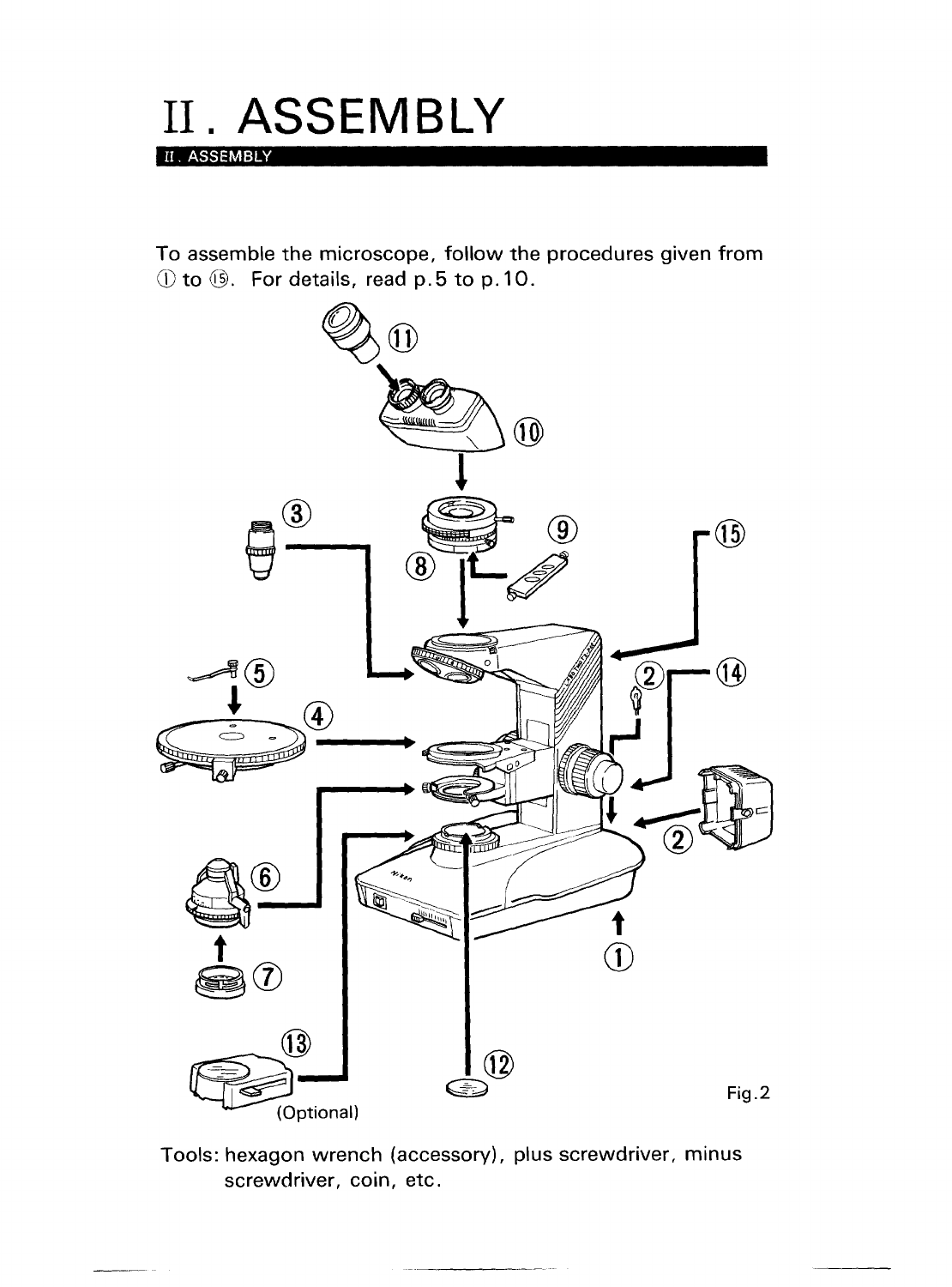
II.ASSEMBLY····································4
III.MiCROSCOPy··························· 11
N .OPERATIONS IN DETAIL .........
17
1 .Orientation
of
the Dia·polarizer
......
17
2.
Focusing and Centering the
Bertrand
Lens'
.............................
18
3.
SWing
Out
the
Top
Lens of the
Condenser
.................................
..
·19
4.1
!4A
& Tint Plate
........................
19
5.
Centering the Objectives
...............
20
6.
Stage Rotation ....·
..
......................
·20
7.
Focusing
....................................
21
8.
Centering the Condenser
...............
22
9.
Use
of
Condenser Aperture
Diaphragm
.................................
23
10.
Use
of
Field
Diaphragm
..............
·24
11 .Optical Path Change·Over........·
..
·24
12
.Interpupillary
DistanceAdjustment·25
13.
Diopter
Adjustment
.....................
25
14.
Oil Immersion
Manipulation
........
·26
15.
Brightness
and
Contrast
Adjustment
...............................
27
16.
Objectives and Eyepieces
............
29
V .OPTIONAL ACCESSORIES ......
30
1.
Senarmont
Compensator
..............
·30
2.
Quartz
Wedge
..............................
31
3.
Pin
Hole Eyepiece
........................
32
4.
Attachable
Mechanical
Stage"
.......
32
5. Universal Epi-illuminator
...............
33
VI.TROUBLESHOOTING ...............
35
ELECTRICAL SPECIFICATIONS
...
41
CARE
AND
MAINTENANCE
DCleaning the
Lenses
To clean the lens surfaces. remove
dust
uSing a soft brush
or
gauze. Only
when
removing
finger
marks
or
grease, use a
soft
cotton
cloth,
lens tissue,
or
gauze
lightly
moistened
With pure alcohol
(methyl alcohol
or
ethyl
alcohol).
For
cleaning the objectives
of
immersion
oil
use
only xylene.
Do
not
use xylene
for
cleaning the surface
of
the entrance lens
of
the eyepiece
tube
or
the prism surface
of
the
Ultra-Wide
Eyepiece Tube
"UW".
Observe sufficient caution
In
handling
alcohol
and xylene (they are
inflammable),
and the ON-OFF
of
the
power
source
sWitch.
fjCleaning the Painted Surfaces
Avoid the
use
of
any organic solvent (for
example,
thinner,
ether, alcohol)
for
cleaning the painted surfaces and plastic
parts
of
the
instrument.
We
recommend
you use the Silicon
cloth.
8lNever Attempt to Dismantle!
Never attempt to dismantle the
instrument because you may
impair
the
functions.
mWhen
Not
in
Use
When
not
in use, cover the
Instrument
with
the accessory vinyl cover, and store
it
in
a place free from moisture and
fungus. It
is
especially
recommended
that
the objectives and eyepieces be kept
In
an
airtight
container
containing
desiccant.
GiPeriodic Checking
To maintain the best
performance
of
the
Instrument,
we
recommend
that the
Instrument
be periodically
checked.
(For
details
of
this check,
contact
your
authOrIZed Nikon
distributor.)
*Please note
as
per
your
Nikon
warranty.
"Any defects or damage directly or
indirectly caused by the
use
of
unauthorized replacement parts
and/or
performed
by
unauthorized personnel"
will void the warranty.
..
II

1
I •
NOMENCLATURE
I . NOMENCLATURE
Intermediate
tube
Nosepiece
centering
screw
Centering revolving
nosepiece
CF
Achromat
P objective
(Strain-free)
Specimen
clip
Circular
graduated
stage
Stage
clamp
screw
Condenser
centering
screw
Condenser
aperture
diaphragm
control
ring
Field
diaphragm
control
ring
Power
switch
Brightness
adjuster
Binocular
eyepiece
tube
Eyepiece
tube
clamp
screw
Bertrand lens
centering
screw
Analyzer
knob
Intermediate
tube
clamp
screw
Revolving nosepiece
clamp
screw
Coarse-focus
torque
adjustment
ring
Fine-focus
scale
Lamp
hOUSing
Arm
rest
Fig.1-1

II.
ASSEMBLY
II.
ASSEMBLY
To
assemble
the
microscope,
follow
the
procedures
given
from
CD
to
@.
For details, read
p.5
to
p.
10.
%@
a®---...6
t
~CV
@
~Ptionall
Fig.2
Tools: hexagon
wrench
(accessory), plus
screwdriver,
minus
screwdriver,
coin,
etc.

Bertrand lens
centering screw
Analyzer
clamp
screw
Analyzer rotation ring
Analyzer scale
Coarse
focus
knob
Fine
focus
knob
Power cord
Condenser
focus
knob
Condenser
clamp
screw
ND filter knob
I.
NOMENCLATURE
Eyepiece
Diopter
ring
Bertrand lens turret
Bertrand lens
focus
ring
1/4'"
&
tint
plate
Vernier
Stage rotation
clamp screw
Condenser
top
lens
swing~out
knob
(Optional)
Fig.1-2
2

5
II.
ASSEMBLY
CD
Leveling Foot Screw
•
For
stable installation
of
the
microscope,
manipulate
the
adjustment
screw
at
the
rear-right
of
the
base
(Fig.2-1).
Fig.2-1
(2)
Lamp and Lamp Housing
ICAUTIONS I
• Use
the
specified
lamp
"Nikon
Halogen
6V
30W".
e Use
the
specified
Halogen
Lamp.
See Electrical
Specifications
on
p.4
1
tor
details .
• Keep
the
lamp
cover
on
or
use gloves
when
mounting
the
lamp
bulb,
so
as
not to touch the surface directly with your fingers.
If
the
bulb
surface
IS
contaminated
with
finger
marks
or
dirt,
wipe
them
off
with
lens
tissue.
Be sure
to
remove
the
lamp
cover
after
mounting
the
lamp.
• Remove
the
lamp
housing
cover
pressing
the
cover
detaching
buttons
(Fig.
2-2).
elnsert
the
lamp
Into
the
socket
pin holes
until
it reaches
the
limit
(Fig.
2-3).
• Reattach
the
cover.
Cautions when dismounting
• Turn
oft
the
power
switch.
(Assure
that
It is
off.)
Do
not
touch
the
lamp-bulb
Immediately
after
turning
It
off
because
It is very
hot.
Wait
until it
cools
enough
for
replacing.
•
Power
supply
cord
should
be kept
away
trom
lamp
housing
while
the
lamp
hOUSing
is
hot.
Fig.2-2 Fig.2-3

II.
ASSEMBLY
Q)
Objectives
•
Screw
in the objectives
to
the holes
of
the revolving nosepiece in
such positions
that,
when
viewed
from
above,
their
magnifying
power
increases
as
the nosepiece
is
revolved
clockwise
(Fig.
2-4).
Cautions when dismounting I
• Remove
the
NO filter cassette
(Ex.)
If attached and
lower
the
stage
by
turning
the
coarse
focus
knob.
• Remove any
specimen
from
the
stage.
• Hold
the
objective so
as
not
to
drop
it
when
unscrewing.
® Stage
•
Lower
the
substage by
turning
the coarse
focus
knob.
• Loosen
the
stage
clamp
screw
sufficiently.
Fig.2-4
• Fit
the
stage to the
circular
dovetail
of
the
substage
00.
Fasten
the
stage
with
the
stage
clamp
screw
~
(Fig.
2-5).
Fig.2-5 Fig.2-6
@ Specimen Clip
.Insert
the
two
speciment
clips into
the
holes on
the
stage surface
(Fig.
2-6).
® Condenser
• Raise the substage by
turning
the coarse
focus
knob.
•
Lower
the
condenser
carrier
to
its
limit
by
turning
the
condenser
focus
knob
.
• Insert
the
condenser
into
the
condenser
carrier
00
with
the
numerical
aperture plate
facing
toward
the
user. Fasten it
with
the
condenser
clamp
screw
~
(Fig.
2-7).
• Raise
the
condenser
carrier
to
its
limit
by
turning
the
condenser
focus
knob.
6

7
II.
ASSEMBLY
Fig.2-7
(J)
Dia-polarizer
Cautions
when
dismounting
• Remove
the
ND filter cassette
if attached .
•
Lower
the
condenser
carrier to
its
limit
by
turning
the
condenser
focus
knob.
Remove
the
condenser
by
releasing
the
condenser
clamp
screw.
• Fit
the
dia-polarizer
into
the
bottom
of
the
condensor
(Fig.
2-8).
Fig.2-8
Fig.2-9
@ Intermediate Tube
•
Mount
the
intermediate
tube
onto
the
microscope
arm
fitting
the
notch
of
the
circular
devetail
of
the
intermediate
tube
with
the end
of
the
clamp
screw.
Tighten
the
clamp
screw
holding
the
mid-stem
of
the
hexgon
wrench.
Do
not
over
tighten
the
screw
holding
the
L-shaped
holder
of
the
wrench.
(Fig.
2-9)
® 1/4A & Tint Plate
• Remove
the
screw
from
the side
of
the
1/4
A plate. Insert
the
plate
Into the
compensator
slot
of
the
intermediate
tube
facing
the
positioning
notches
toward
the user.
Screw
in
the
screw
once
removed
(Fig.
2-10).
Fig.2-10
Fig.2-11

II.
ASSEMBLY
@ Binocular Eyepiece Tube
e
Mount
the eyepiece
tube
onto
the
intermediate
tube
fitting
the
notch
of
the
circular
dovetail
of
the
eyepiece
tube
with
the end
of
the
clamp
screw.
Tighten
the
clamp
screw
using the hexagon
wrench.
(See @ and
Fig.2-11
.)
ICautions when clamping I
eTighten
the eyepiece
tube
clamp
screw
holding
the stem
of
the
hexagonal
wrench.
If overtightened
holding
the
plastic
part,
optical-path
change-over
of
the
eyepiece
tube
may be
malfunctioned.
QJ)
Eyepiece
e Use
the
same
magnification
eyepieces
for
both
the
right and left
eyes.
elnsert
the
eyepieces into
the
sleeves
of
the
binocular
eyepiece
tube
by
engaging
the
three grooves
of
the
eyepiece
with
the
three
protrusions
of
the sleeve (Fig.
2-12).
e
When
using eyeguard
rubbers,
put
them
onto
the eyepieces
(Fig.2-13).
Fig.2-12
*Rotation
clamp ring for the eyepiece
Fig.2-13
The rotation
clamp
ring
is
mounted
on the eyepiece sleeve
to
prevent the rotation
of
the
eyepiece.
When
removing
the
eyepiece, take care not to accidentally hold this
ring
and
pull
it out together with the eyepiece.
Rotation
clamp ring
for
the
eyepiece
Fig.2-14
8

9
II.
ASSEMBLY
The rotation
clamp
ring
must
be removed
when
mounting
the old
type
of
eyepiece.
When
attaching
the ring
again,
note on the
following
points.
uCaution
when attaching rotation clamp
ring
Hold
the ring so
that
the
¢O.8
protrusion
on
the brim faces
up.
There are
two
pawls
on
the
ring
and
two
grooves
on
the sleeve
to
prevent
the
ring
from
failing
off.
Attach the
ring
so
that these pawls
and grooves fits together.
O.
8-diameter
protrusion
Pawls
Rotation
clamp
ring
for
the
eyepiece
Grooves
@ Filter on the Filter Receptacle
Binocular
eyepiece
tube
sleeve
Fig.2-15
Place the
¢45mm
filter on the filter receptacle
of
the
field lens part
(Fig.
2-16).
Fig.2-16
Fig.2-17
@ ND Filter Cassette (optional)
• Push
down
the
ND
filter cassette so the
two
protrusions
of
the
cassette
bottom
fit
with
the
two
mounting
grooves on the rim
of
te
field lens
part
(Fig.
2-17)
.
•
When
frequently
lowering
the stage,
mount
the
ND
filter cassette
in
the
direction
as
shown
in Fig.
2-18
.
•
When
dismounting,
push the cassette either
to
the
left
or
right
and
raise the
opposite
side.

II.
ASSEMBLY
Fig.2-18 Fig.2-19
@ Power Cord
e
Connect
the socket of
the
power
cord
to
the AC inlet on
the
rear
of
the
base (Fig.
2-19).
Plug in
the
other
end
of
the
cord
to an AC line
receptacle
with
the
ground
conductor
(earth
conductor).
For
100-120Varea------------------------------~
e Use only the
following
power
supply
cord set.
UL listed, detachable cord set.
3-conductor
grounding
type SVT,
No.
18
AWG
rated a
minimum
1
25V,
7A.
el
n case
of
using
the
extension
cord,
use only
the
power
supply
cord
including
PE
wire.
For220-240Varea------------------------------~
e Use only the
3-pole
power
supply
cord
type
H05VV-F
or
H05VVH2-F,
which
must
be approved
according
to
DIN VDE
0625.
The plug and the
outlet
are
to
be approved
according
to
DIN
VDE
0620
and DIN VDE
0625,
respectively.
e Class I
equipment
should
be
connected
to
PE
(protective earth)
terminal.
eln
case
of
using
the
extension
cord,
use only the
power
supply
cord
including
PE
wire.
@ Hexagon Wrench
e The hexagon
wrench
IS stored
in
the back
of
the
microscope
sta nd .
Take it
out
as
shown
in
Flg.2-20.
Fig.2-20
10

11
III.
MICROSCOPY
III. MICROSCOPY
Fig.3-1
Fig.3-2
-""'
...
-----
....
,
;,,;
'\
" \
, '
f'MoTe ,
:~I
II~/
Fig.3-3
Fig.3-4
1) Put
the
NCB
11
filter
(or
necessary filter) on
the
filter
receptacle
of
the
field lens part
(Flg.3-1).
2)
Mount
the
optional
ND
filter
cassette, if used (Fig.
3-2).
(Refer to II.
ASSEMBLY-
@
p.9.)
3) Turn on
the
power
switch
rn
to
light
the
lamp.
Move
the
brightness
adjuster
and
align it
with
the
3rd
scale
line
from
the
right
~
(Fig.
3-3).
4) Pull
the
analyzer
knob
of
the
intermediate
tube
rn
to
remove
the
analyzer
from
the
optical
path.
Turn
the
Bertrand lens
turret
to
the
position
"0"
~
to
remove
the
Bertrand lens
from
the
optical
path
(Fig.3-4).

Fig.3-5
Fig.3-6
Fig.3-7
Fig.3-8
Ill.
MICROSCOPY
5)
Move the filter knobs
of
the
ND
filter cassette
to
the
limit
to
bring all
ND
filters into the
optical path (Fig.
3-5).
6) Revolve the revolving nosepiece
to
swing in
the
10
x objective
to
the optical
path.
Assure
that
the nosepiece properly settles
in
position (Fig.
3-6).
7} Place the specimen (glass slide)
on the stage
with
its cover glass
facing
up
and fasten it
with
the
two
specimen clips (Fig.
3-7).
8} Raise the
condenser
uppermost
using the
condenser
focus
knob
(Fig.
3-8).
12

1Il. MICROSCOPY
13
Fig. 3-10
Binocular
part:
100%
.....
Fig.3-11
Fig.3-12
Fig.3-9
9)
Fully open
the
field and aperture
diaphragms
(Fig.
3-9).
10)
Bring
the
object
portion
of
specimen
into
the
optical path
(Fig. 3-1
0).
(Object
portion
IS
just
above the
condenser
lens.)
11)
When
the
trinocular
eyepiece
tube
is
used,
change
the
optical path
of
the eyepiece
tube
to enter
100%
of
the
light
into
the
binocular
part
(Fig.3-11).
(See
p.
24,
Operations in
Detail-11.)
12)
Focus on
the
specimen
looking in
the
eyepiece by
manipulating
the
coarse/fine
focus
knob
(Fig.3-12).

Fig
.3-13
Fig.3-14
Fig.3-15
Ill.
MICROSCOP
13)
Adjust the
diopter
(Fig.
3-13).
(See
p.
25,
Operations
in
Detail-1
3.)
14) Adjust the interpupillary
distance (Fig. 3-1
4).
(See p.
25,
Operations
in
Detail-1
2.)
15)
Center
the
obj.ective
(Fig.3-15).
(See
p.
20,
Operations in
Detail-5.)
14

15
III. MICROSCOPY
Image
of
field
diaphragm
Eyepiece
viewfield stop
Image of field
diaphragm
Eyepiece
~
viewfield stop
Fig.3-16
Fig.3-17
16)
Focus
and
center
the
condenser
(Fig.
3-16).
(See
p.
22,
Operations
In
Detall-8.
)
17)
Push
In
the
analyzer
knob
to
put
the
analyzer Into
the
optical
path
(Fig.
3-17).
18)
Revolve
the
revolving
nosepiece
to
the
objective
to
be used
and
focus
on
the
specimen
by
manipulating
the
fine
or
coarse
focus
knob.
(See
Note:
2.)
When
using
an oil
immersion
objective,
apply
oil
to
the
space
between
the
top
of
the
objective
and
the
specimen.
Take care
not
to
produce
bubbles
in
the
oil.
(See
p.
26,
Operations
In
Detail-14.)
19)
When
the
ND
filter
cassette is
used,
Adjust
the
brightness
by
sliding
the
filter
knob.
(See
p.
27,
Operations
In
Detail-l
5.)
When
the
ND
filter
cassette
is
not
used,
adjust
the
brightness
of
the
lamp
by
manipulating
the
brightness
adjuster.
20)
Adjust
the
viewfleld
and
the
aperture
diaphragms
by
manipulating
their
respective
control
rings. (See
p.
23
and
24,
Operations
In
Detail-9
and
-10.)

III. MICROSCOPY
Table 1
Orthoscopic
microscopy
Conoscopic
microscopy
10
x or IN
Top lens
of
higher
condenser
4x
or
IN
lower
OUT
Bertrand lens OUT IN
lOx
or
70%~80%
of
the
Circumscribed
the
Aperture
higher
numerical
aperture
circumference
of
the
of
the
objective
diaphragm
4x
or
Fully opened
conoscoplc
field
of
view
lower
(or fully opened)
10x
or
Circumscribed
the
Circumference
of
the
Circumscribed
the
higher
Field
diaphragm
eyepiece
field
of
view
circumference
of
the
4x
or
lower
Fully opened
orthoscopic
field
of
view
Note 1 Manipulate the
condenser
centering screws if part
of
the
viewfield
is
dark. If this
doesn't
help, check the
following
items:
elnsertion/removal
of the
ND
filter
eTurning
the
revolving
nosepiece (click-stop position)
e Position
of
the
condenser
eViewfield
and aperture
diaphragms
fully open
e Change-over of the optical
path of the eyepiece tube
e
Mounting
the
lamp
e
Mounting
the
condenser
e Placing the filter on the filter
receptacle
III. MICROSC;:OPY-5)
III. MICROSCOPY-6)
III. MICROSCOPY-B)
III. MICROSCOPy-g)
III.
MICROSCOPY-ll)
II.
ASSEMBLY-CZ)
Lamp and Lamp
Housing
II.
ASSEMBLY-@
Condenser
II.
ASSEMBLY-@
Filter on the Filter
Receptacle
Note 2 Check the
following
items
when
the specimen
cannot
be
focused.
e Placing the specimen III. MICROSCOPY-7)
eThickness
of
the cover glass (standard
=0.
17mm)
16

17
N.
OPERATIONS
IN
DETAIL
(Operation
part)
N.
OPERATIONS
IN
DETAIL
1. Orientation
of
the Dia-polarizer
(Dia-polarizer and analyzer)
CD
Place the specimen on
the
stage,
focus
on the specimen using
the
objective
40
x .
® Set
the
analyzer scale on
the
intermediate
tube
to
o.
G)
Insert
the
dia~polarizer
into
the
bottom
of
the
condenser
as
shown
in
Fig
.4.
Dark cross image
Fig.4 Fig.5
® Remove the eyepiece
from
the
sleeve or
put
the
Bertrand lens into
the
optical path. Observing the exit pupil
of
objective inside, rotate the
dia~polarizer
so
as
to
form
a dark cross image on
the
exit pupil
as
shown
in
Fig.
5.
eThe analyzer can be rotated by
loosening
the analyzer
clamp
screw
rn
and rotating the rotation ring
~.
The rotation angle can be read
in
the
range between
O·
to
180"
with
the
unit
of
0.1·
by
the
vernier.
The analyzer can be removed
from
the
optical path by
pulling
the
analyzer
knob~.
(Fig.6)
Note I As
the
depolarizer
is
built
in
the
intermediate
tube,
you
don't
need to be
concerned
about
the relation between
the
orientation of the polarizing plate and
photomicrographic
device.
Fig.6

N.
OPERATIONS
IN
DETAIL
2.
Focusing
and
Centering
the
Bertrand
Lens
(Bertrand lens
of
the intermediate tube)
•
When
objectives
are
replaced.
turn
the
Bertrand lens
focus
ring
under
the
Bertrand
lens
turret
and
focus
the
Bertrand lens.
Centering
is
carried
out
uSing
the
condenser
aperture
diaphragm
Image
and
the
two
centering
screws.
(Fig. 7)
Centering
procedure
for
the
Bertrand lens is
the
same
as
that
for
the
condenser
except
that
the
condenser
aperture
diaphragm
image
is
used in place
of
the
field
diaphragm
image
In
condenser
contering.
(Refer
to
Item
8.)
Note I
Another
Bertrand
lens
IS
built
in
the
optional
tnnocular
eyepiece
tube.
Turn
the
Bertrand lens
nng
to
the
position
"B".
and
the
Bertrand lens will be
brought
into
the
optical
path and a
conoscope
image
may
be
observed.
(Fig. 8)
Fig.7
Fig.S
18
Table of contents
Other Nikon Microscope manuals

Nikon
Nikon Alphaphot User manual

Nikon
Nikon Microphot-FXA User manual

Nikon
Nikon ECLIPSE Ni-E User manual

Nikon
Nikon ECLIPSE E600 POL User manual

Nikon
Nikon LABOPHC-POL User manual

Nikon
Nikon S-kt User manual

Nikon
Nikon A1+ User manual

Nikon
Nikon Eclipse Series User manual

Nikon
Nikon P-400R User manual

Nikon
Nikon 50i User manual

Nikon
Nikon LABOPHOT-2 User manual

Nikon
Nikon ECLIPSE Ti2-U User manual

Nikon
Nikon LABOPHOT-POL User manual

Nikon
Nikon Optiphot 66 User manual

Nikon
Nikon T1-FM User manual

Nikon
Nikon SMZ25 User manual

Nikon
Nikon Eclipse LV100POL User manual

Nikon
Nikon SMZ25 User manual

Nikon
Nikon E800 User manual

Nikon
Nikon ECLIPSE Ei User manual