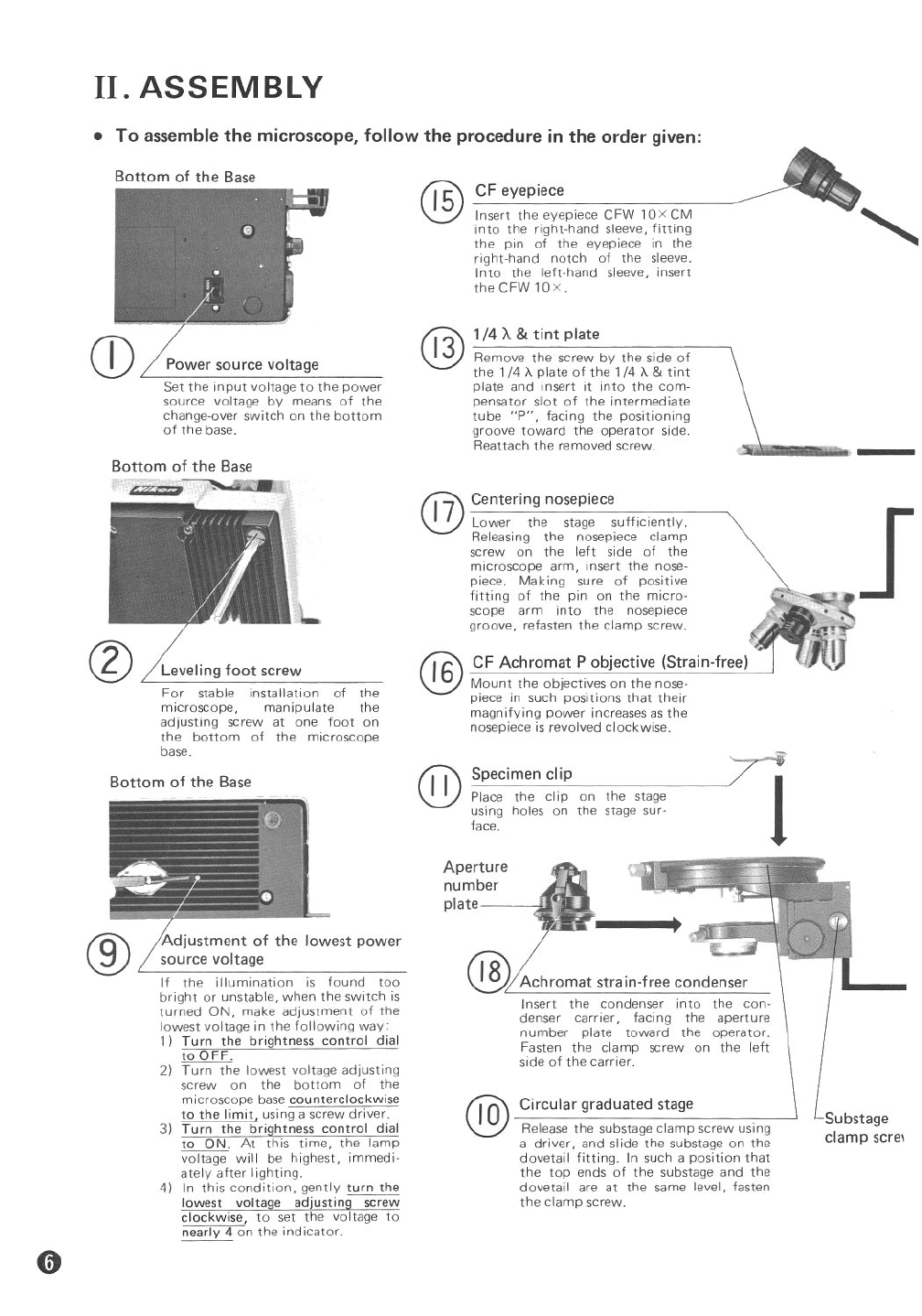
II. ASSEMBLY
• To assemble the microscope, follow the procedure in the order given:
Substage
clamp scre,
Achromat strain-free condenser
Insert the condenser into the con-
denser carrier, facing the aperture
number plate toward the operator.
Fasten the clamp screw on the left
side of the carrier.
Circular graduated stage
Release the substage clamp screw using
a driver, and slide the substage on the
dovetail fitting. In such a position that
the top ends of the substage and the
dovetail are at the same level, fasten
the clamp screw.
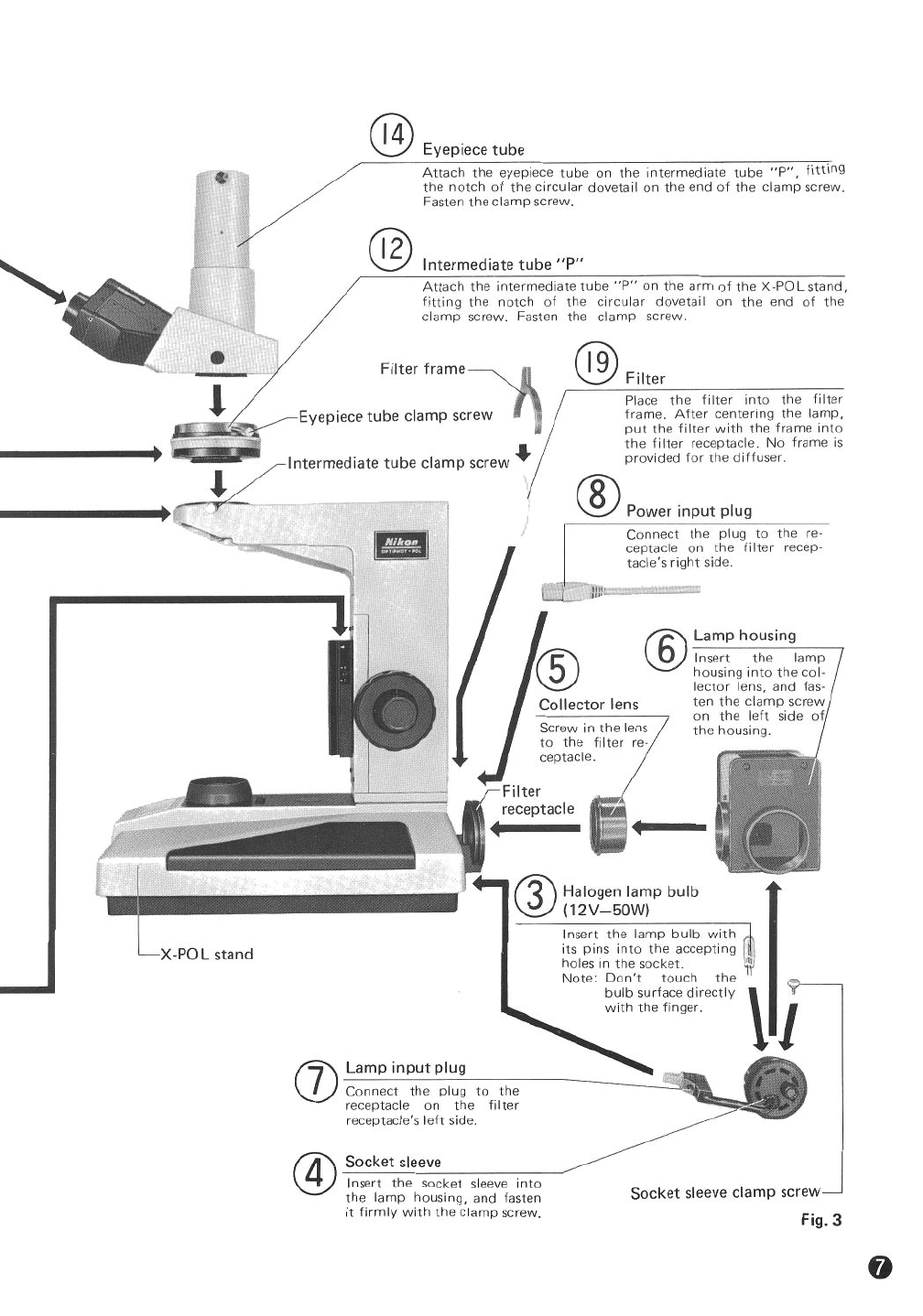
CF eyepiece
Insert the eyepiece CFW 10XCM
into the right-hand sleeve, fitting
the pin of the eyepiece in the
right-hand notch of the sleeve.
Into the left-hand sleeve, insert
theCFW10X.
1/4 A&tint plate
Remove the screw by the side of
the 1/4 "A. plate of the 1/4 "A. & tint
plate and insert it into the com-
pensator slot of the intermediate
tube "P", facing the positioning
groove toward the operator side.
Reattach the removed screw.
Specimen clip
Place the clip on the stage
using holes on the stage sur-
face.
@
Aperture
number
plate
@Centering nosepiece
17 Lower the stage sufficiently.
Releasing the nosepiece clamp
screw on the left side of the
microscope arm, insert the nose-
piece. Making sure of positive
fitting of the pin on the micro-
scope arm into the nosepiece
groove, refasten the clamp screw.
@
@6CF Achromat P objective (Strain-free)
Mount the objectives on the nose-
piece in such positions that their
magnifying power increases as the
nosepiece is revolved clockwise.
@
lowest power
Leveling foot screw
For stable installation of the
microscope, manipulate the
adjusting screw at one foot on
the bottom of the microscope
base.
Power source voltage
Set the input voltage to the power
source voltage by means of the
change-over switch on the bottom
of the base.
If the illumination is found too
bright or unstable, when the switch is
turned ON, make adjustment of the
lowest voltage in the following way:
1) Turn the brightness control dial
to OFF.
2) Turn the lowest voltage adjusting
screw on the bottom of the
microscope base counterclockwise
to the limit, using a screw driver.
3) Turn the brightness control dial
to ON_ At this time, the lamp
voltage will be highest, immedi-
ately after lighting.
4) In this condition, gently turn the
lowest voltage adjustingsc;:ew
clockwise, to set the voltage to
nearly 4 on the ind icator.
Bottom of the Base
Bottom of the Base
~-------
~
Bottom of the Base