manuals.online logo
Brands
  1. Home
  2. •
  3. Brands
  4. •
  5. NIVELCO
  6. •
  7. Switch
  8. •
  9. NIVELCO NIVOCONT K User manual

NIVELCO NIVOCONT K User manual

1. APPLICATION
The conductive measuring principle can be applied to liquids with specic conductivity over
10 μS/cm. The switching unit can sense the resistance between probes. Conductivity measure-
ment is suitable only for detecting the presence of liquid at a given level of the tank. This level
is represented by the length of the probe.
The level switch consists of a NIVOCONT KRK–622– type switching unit and the
KLN–2 type probes selected according to the task. Probes are to be connected to the
NIVOCONT KS– 0 type probe socket head that can be screwed into the tank.
If the material of the tank or its internal insulation is not conductive then a reference probe
should be used in addition to the one, two, three or four probe(s), if the material of the tank is
conductive, the tank can be used as a reference probe.
The conductive switch is suitable for lling-emptying control with 2 relay outputs working simul-
taneously or for level detection of 2 independent levels (in 1 or 2 tanks) with 2 independent relay
outputs. More level switches can also be used with one common reference probe ‘C’ using any
combination of multiple-probe and single-probe socket.
2. TECHNICAL DATA
2.1 GENERAL DATA
2.1.1 Switch
KRK–622–1, –2 KRK–622–4
Probe voltage max. 3.5 V AC
Probe current < 1 mA AC
Sensitivity Adjustable: 5…100 kΩ
Max. cable capacitance 800 nF (sensitivity 5 kΩ)
100 nF (sensitivity 100 kΩ)
Response time max. 400 ms
Mechanical accuracy ±5%
Delay Adjustable: 0.5…10 s
Relay output 2× SPDT
Switching voltage 250 V AC1, 24 V DC
Switching current 16 A AC1
Switching power 4000 VA AC1, 384 W DC
Min. output power DC 4 kV (power – output)
Mechanical life-span 3 × 10⁷switches
Electrical life-span 0.7 × 10⁵switches
Power supply Un
230 V or 110 V AC 24 V AC/DC
Galvanically separated (AC 50/60 Hz)
Voltage range allowed Nominal voltage –15%…+10%
Power consumption 2.5 W / 5 VA (230 V AC, 110 V AC),
1.4 W / 2 VA (24 V AC/DC)
Ambient temperature –20…+55 °C
(–4…+131 °F)
Electrical connection max. 2.5 mm2
(AWG14)
Overvoltage category II
Pollution degree 2
Electrical protection Class II Class III
Ingress protection IP20
Mechanical connection DIN EN 60715 rail
Weight 248 g
(0.55 lb)
147 g
(0.32 lb)
krk622en1905h ♦ page 1
Thank you for choosing a NIVELCO instrument! NIVOCONT K
KRK–622
CONDUCTIVE LEVEL SWITCH
Manufacturer:
NIVELCO Process Control Co.
H–1043 Budapest, Dugonics u. 11.
Tel.: +36-1-889-0100 Fax: +36-1-889-0200
E-mail: sales@nivelco.com www.nivelco.com
USER’S MANUAL
PDF 
KRK–622–NIVOCONT KS–0
Type Code
Cable probe K
SINGLE PROBE
PP socket P
Carbon steel socket S
Stainless steel socket N
MULTIPLE PROBES
Stainless steel socket H
Housing mat. Code
Aluminum 2
Plastic 3
Probe number Code
1 + reference probe* 1*
2 + reference probe 2
3 + reference probe 3
4 + reference probe 4
Power supply Code
230 V AC 1
110 V AC 2
24 V AC/DC 4
2.2 ORDER CODES (NOT ALL CODE VARIATION AVAILABLE)
2.4 DIMENSIONS
2.3 ACCESSORIES
– User’s Manual
– Warranty Card
– EU declaration of conformity
– Seal (2 mm
[0.08"]
thick)
(KLINGER OILIT)
:
1× ⅜" (KSP–201, KSS–201, KSN–201)
1× 1½" (KSH–20

)
– M6 nut (standard SW):
3× (KSH–202)
4× (KSH–203, KSH–204)
– M6 nut (non-st. SW)
1× (KSH–204)
KSK–
201
KSP–
201
KSS–
201
KSN–
201
KSH– KLN–
2

KLP–
201
KLP–
204
202 203 204 301 302 303 304
Number of probes 12+r 3+r 4+r 1+r 2+r 3+r 4+r 1–
I
nsulation of socket
ABS PP PFA PP –
Cable gland Pg7(1) M4 nut,
protected by a rubber cap
M20x1.5
cable diameter Ø6…12 mm
(Ø0.25…0.5 inch)
– –
Process conn. – ⅜" BSP 1½" BSP M6 –
Socket material – PP A44
c. steel
KO35
stainless steel (1.4571) PP KO35
1.4571 –
Housing material – Powder-coated
cast aluminum PBT – PP PVDF
Medium
temperature
max. +80 °C
(+176 °F)
max. +200 °C
(+391 °F)
max. +80 °C
(+176 °F)
–
max.
+80 °C
(+176 °F)
max.
+130 °C
(+266 °F)
Max. pressure – 3 bar
(43.5 psi)
16 bar
(232 psi)
3 bar
(43.5 psi)
–
Ingress protection – IP20 IP65 IP67 –
Mass 50 g
(0.11 lb)
100 g
(0.22 lb)
400 g
(0.88 lb)
220 g/m
(0.13 lb/ft)
–
r = reference probe (1) cable: Ø4…7 mm
2.1.2 Probe sockets
Pg7
M20x1.5
SW55
⅜" BSP
Switch
KRK–622–
Cable Probe
KSK–201
Probe Socket
KSH–20
Probe Socket
KSP–201 / KSS–201 / KSN–201
Probe
KLN–2
Uninsulated base probe
M20x1.5
85
Probe Socket
KRK–512–
Separator
KLP–204
Probe Socket
KSH–30
Separator
KLP–201
KLN–2
Code Probe length Code
00 m 0 m 0
11 m
(3.3 ft)
0.5 m
(1.64 ft)
5
22 m
(6.6 ft)
33 m
(10 ft)
Separator:
NIVOCONT KLP–201 – for plastic version
NIVOCONT KLP–204 – for aluminum version
*only plastic version
krk622en1905h ♦ page 2
3. INSTALLATION
A KRK–622– switching unit can be mounted on DIN EN 60715 rail.
It is recommended the KLN–2 type probes to be cut to the length required for level detec-
tion on site. The probes should be screwed into the KS–0 type sockets.
ALWAYS REMEMBER TO TIGHTEN THE PROBE WITH AN M6 NUT!
When using KSH–204 type probe sockets the reference probes should be tightened with spe-
cial SW hexagonal M6 nuts!
It is suggested KLP–201 or KLP–204 type PVDF separators (suitable up to +130 °C) to be
used at every 0.5 m for multiple probe devices to keep the probes apart.
A KSK–201 single probe, attached to an insulated cable, can be lowered into pits and wells
without running the risk of a short circuit. When a detection is needed in a well or in a plastic
pipe 2 of them have to be used. For additional levels additional probes should be used.
4. WIRING
If the wall of the tank is conductive no reference probe is needed. In this case terminal ‘C’
has to be connected to the tank.
On multiple probe units ‘E1’ and ‘E2’ are marked with 1–4, the reference probe is marked
with ‘C’. Admissible length of cable between switching unit and probes depends on cable
capacitance and conductivity.
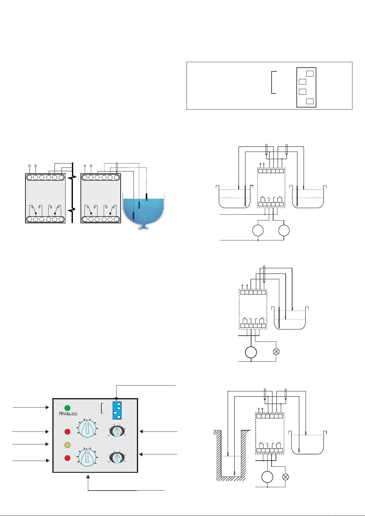
The terminal block assignment of KRK–622–1 and KRK–622–2 is not the same, the
KRK–622–4 is different. There is no ‘S’ terminal at the KRK–622–1 and KRK–622–2. Refer-
ring to the illustration below for the terminal block assignments of the devices.
Example of setting DIP switch:
Select the desired function in accordance with the gures. The upper 3 switches are for select-
ing the number of the function you want to use. If you want to use Function 5 you should set
the switches as follows: set the 1st switch to the right, the 2nd to the left and the 3rd to the left.
Then select whether you need ON delay or OFF delay with the 4th switch. You can choose the
type of delay, but you cannot deactivate the delay. However, the minimum delay time you can
set with the potentiometers is 0.5 seconds.
The DIP switch looks like this after setting function 5 with an OFF delay:
Un
OUT2
S
E1E2
C
A2A1
OUT1
16 15 18 28 25 26
Un
KRK–622–1,–2 KRK–622–4
C
E2
E1
E2
C
A2A1 E1
OUT2OUT1
16 15 18 28 25 26
A1, A2 – power supply S – shielding
C – reference probe 15, 16, 18 – 1st relay output – pump control 1
E1 – max. probe (OUT1) 25, 26, 28 – 2nd relay output – pump control 2
E2 – min. probe (OUT2) (function 1, 2, 3, 4) or alarm (function 5, 6, 7, 8)
To eliminate signal interferences it is recommended to use shielded cables to the probes.
5. COMMISSIONING
5.1. ADJUSTMENT
The green LED (Un) shows that the unit is on, the energised state of the relays are indicated by
the OUT1 respectively OUT2 LEDs. If the OUT1, OUT2 (red) LEDs are ashing, they indicate
the timer operation. When they light up, it shows that the corresponding relay is switched
on. Yellow LED (FAIL) indicates probe failure (for example at Functions 5 and 6 probe ‘E1’ is
ooded and probe ‘E2’ is not, which is unreal state so the yellow LED is on.)
Operating modes, delay ON and delay OFF can be set with the DIP switch on the front panel.
t1[s] and t2[s] potentiometers are for adjusting the delay time. The delay value can change
from 0.5 seconds to 10 seconds. You can set the sensitivity of the two probes independently
using the RE1 or RE2 potentiometers. The sensitivity setting should comply with the conduc-
tivity of the uid. Do not set sensitivity higher than required because the vapour precipitation
may lead to operation disturbance. In heavily humid environment insulated probes can be
used. With the ON Delay / OFF Delay switch on the DIP switch, delay type of the relays can
be selected (switch-on delay or switch-off delay).
5
10
20
30 50
70
90
100
t [s]
1
t [s]
2
KRK22–6
Un
OUT1
OUT2
FAIL
10
30 50
70
90
100
R[ ]
E1 Ωk
OFF
Delay
ON
Delay
Function
1,2,3,4
1,2,5,6
1,3,5,7
20
R[ ]
E2 Ωk
5,6,7,8
3,4,7,8
2,4,6,8
5
OUT2 switching
indication
Delay adjustment
for Relay 1
DIP switch
(Function 7 is showed on the picture)
Delay adjustment
for Relay 2
2 rotary potentiometers for adjusting the
sensitivity for E1 and E2 probes independently
according to the conductivity of the uid
Probe failure
OUT1 switching
indication
Supply voltage
indication
1st switch to right
2nd switch to left
3rd switch to left
Function
1, 2, 3, 4
1, 2, 5, 6
1, 3, 5, 7
5, 6, 7, 8
3, 4, 7, 8
2, 4, 6, 8
ON DelayTo off delay switch to right OFF Delay
5.2 FUNCTIONS
Attention! The following wiring diagrams show the wiring of the KRK–622–4,
24 V supply voltage device.
Functions 1 to 4 are for controlling 2 pumps according to the following picture:
A1 A2 C E2 E1 S
16 15 18 28 25 26
Un
L
N
E2
CC E1
OUT 1 OUT 2
Tank I.
Pump 1 Pump 2
Tank II.
Functions 5 and 6 are for controlling one pump (lling or emptying one tank) and for generating
alarm signal according to the following picture. If level is not between ‘E1’ and ‘E2’ alarm is
generated:
A1 A2 C E2 E1 S
16 15 18 28 25 26
Un
L
N
C
E2
E1
max.
min.
OUT 1 OUT 2
Tank
Alarm
Pump
Functions 7 and 8 also controls one pump and generates one alarm signal:
A1 A2 C E2 E1 S
16 15 18 28 25 26
Un
L
N
OUT 1 OUT 2
E2
C C E1
Alarm
Well
Reservoir
Tank
Pump
Front panel of NIVOCONT KRK–622
krk622en1905h ♦ page 3
FUNCTION 1
Controlling level in 2 separate tanks (each with 1 probe) – lling. The pumps are running and
ll the tanks until the levels reach the corresponding probes (E1 or E2).
Relay 1 (E1): Pump control 1
Relay 2 (E2): Pump control 2
FUNCTION 2
Controlling level in 2 separate tanks (each with 1 probe) – emptying. The pumps are running
and emptying the tanks until probes are ooded.
Relay 1 (E1): Pump control 1
Relay 2 (E2): Pump control 2
FUNCTION 3
Controlling level in 2 separate tanks (each with 1 probe). Pump 1 is emptying the tank and
stops when probe ‘E1’ is not ooded anymore. Pump 2 is lling the tank and stops if level
reaches probe ‘E2’.
Relay 1 (E1): Pump control 1
Relay 2 (E2): Pump control 2
FUNCTION 4
Controlling level in 2 separate tanks (each with 1 probe). Pump 2 is emptying the tank and
stops when probe ‘E2’ is not ooded anymore. Pump 1 is lling the tank and stops if level
reaches probe ‘E1’.
Relay 1 (E1): Pump control 1
Relay 2 (E2): Pump control 2
FUNCTION 5
Both probes and reference probe are in one tank. Relay 1 controls the pump, which keeps
the tank lled and maintains the level between probes ‘E1’ and ‘E2’. Relay 2 is used to alarm
signalling. Relay 2 is on if the level is not between the two probes.
Relay 1 (E1): Pump control 1
Relay 2 (E2): Alarm
FUNCTION 6
Both probes and reference probe are in one tank. Relay 1 controls the pump, which keeps
the tank empty and maintains the level between probes ‘E1’ and ‘E2’. Relay 2 is used to
alarm signalling. Relay 2 is on if the level is not between the two probes.
Relay 1 (E1): Pump control 1
Relay 2 (E2): Alarm
FUNCTION 7
Pumping from well to the tank – probe ‘E2’ is in the well, probe ‘E1’ is in the tank. The pump
only runs if probe ‘E2’ is ooded (enough water in the well) and the tank is not full meaning
the level does not reach probe ‘E1’. The alarm reports a lack of water in the well (probe ‘E2’
is not ooded).
Relay 1 (E1): Pump control 1
Relay 2 (E2): Alarm
FUNCTION 8
Pumping from reservoir to the tank – probe ‘E2’ is in the reservoir, probe ‘E1’ is in the tank.
The pump only runs if probe ‘E2’ is ooded (full reservoir) and the tank is not full (probe ‘E1’).
The alarm reports the status of full tank and reservoir (both probes are ooded).
Relay 1 (E1): Pump control 1
Relay 2 (E2): Alarm
5.3 TIME DIAGRAMS
FUNCTION 1, 3, 4 – PUMP UP (FILLING), ON DELAY:
t
probe
LED
relay
FUNCTION 1, 3, 4 – PUMP UP (FILLING), OFF DELAY:
t
probe
LED
relay
FUNCTION 2, 3, 4 – PUMP DOWN (EMPTYING), ON DELAY:
t
probe
LED
relay
FUNCTION 2, 3, 4 – PUMP DOWN (EMPTYING), OFF DELAY:
t
probe
LED
relay
FUNCTION 5 – PUMP UP (FILLING), ON DELAY:
tD tD
tH
probe H
probe D
LED H
LED D
relay 15-18
relay 25-28
FUNCTION 5 – PUMP UP (FILLING), OFF DELAY:
tD tD
tH
probe H
probe D
LED H
LED D
relay 15-18
relay 25-28
FUNCTION 6 – PUMP DOWN (EMPTYING THE TANK), ON DELAY:
tD tD
tH
probe H
probe D
LED H
LED D
relay 15-18
relay 25-28
FUNCTION 6 – PUMP DOWN (EMPTYING THE TANK), OFF DELAY:
tD tD
tH
probe H
probe D
LED H
LED D
relay 15-18
relay 25-28
FUNCTION 7 – PUMP FROM WELL TO TANK, ON DELAY:
tH tH
probe H (tank)
probe D (well)
LED H
LED D
relay 15-18 (Pump)
relay 25-28 (Alarm)
FUNCTION 7 – PUMP FROM WELL TO TANK, OFF DELAY:
tH
tD
probe H (tank)
probe D (well)
LED H
LED D
relay 15-18 (Pump)
relay 25-28 (Alarm)
FUNCTION 8 – PUMP FROM RESERVOIRS TO TANK, ON DELAY:
tH tH
probe H (tank)
probe D (reservoirs)
LED H
LED D
relay 15-18 (Pump)
relay 25-28 (Alarm)
FUNCTION 8 – PUMP FROM RESERVOIRS TO TANK, OFF DELAY:
tH
tD
probe H (tank)
probe D (reservoirs)
LED H
LED D
relay 15-18 (Pump)
relay 25-28 (Alarm)
krk622en1905h ♦ page 4
6. MAINTENANCE AND REPAIR
The device does not require regular maintenance. The warranty card contains the
terms and conditions. Before returning the device for repairs, it must be cleaned
thoroughly. The parts in contact with the medium may contain harmful substanc-
es; therefore, they must be decontaminated. Our ofcial form (Returned Equipment
Handling Form) must be lled and enclosed in the parcel. Download it from our
website www.nivelco.com. The device must be sent back with a declaration of de-
contamination. A statement must be provided in the declaration that the decontam-
ination process was successfully completed and that the device is clean from any
hazardous substances.
7. STORAGE CONDITIONS
Storage temperature: –30…+70 °C (–22…+158 °F)
Relative humidity: max. 85%.
krk622en1905h
December 2019
NIVELCO reserves the right to change technical data without notice.

This manual suits for next models

4

Other NIVELCO Switch manuals

NIVELCO MR Series User manual

NIVELCO

NIVELCO MR Series User manual

NIVELCO Nivocap CK User manual

NIVELCO

NIVELCO Nivocap CK User manual

NIVELCO NIVOFLIP MAK-100 Series User manual

NIVELCO

NIVELCO NIVOFLIP MAK-100 Series User manual

NIVELCO NIVOSWITCH R-400 Series User manual

NIVELCO

NIVELCO NIVOSWITCH R-400 Series User manual

NIVELCO NIVOPOINT User manual

NIVELCO

NIVELCO NIVOPOINT User manual

NIVELCO NIPRESS DK-500 Assembly instructions

NIVELCO

NIVELCO NIPRESS DK-500 Assembly instructions

NIVELCO NIVOPOINT MR Series User manual

NIVELCO

NIVELCO NIVOPOINT MR Series User manual

NIVELCO NIVOMAG MK-21 Series User manual

NIVELCO

NIVELCO NIVOMAG MK-21 Series User manual

NIVELCO R-400 User manual

NIVELCO

NIVELCO R-400 User manual

NIVELCO NIVOSWITCH R-400 Series User manual

NIVELCO

NIVELCO NIVOSWITCH R-400 Series User manual

NIVELCO NIVOSWITCH R-400 Series User manual

NIVELCO

NIVELCO NIVOSWITCH R-400 Series User manual

NIVELCO NIVOSWITCH R-400 User manual

NIVELCO

NIVELCO NIVOSWITCH R-400 User manual

NIVELCO NIVOFLIP MAK-200 User manual

NIVELCO

NIVELCO NIVOFLIP MAK-200 User manual

NIVELCO NIVOSWITCH R-2 Series User manual

NIVELCO

NIVELCO NIVOSWITCH R-2 Series User manual

NIVELCO NIVOFLOAT NW-100 Series User manual

NIVELCO

NIVELCO NIVOFLOAT NW-100 Series User manual

NIVELCO NIVOCONT R Series User manual

NIVELCO

NIVELCO NIVOCONT R Series User manual

NIVELCO NIPRESS DK-300 Assembly instructions

NIVELCO

NIVELCO NIPRESS DK-300 Assembly instructions

Popular Switch manuals by other brands

Ponca Technologies PT-2081 user manual

Ponca Technologies

Ponca Technologies PT-2081 user manual

Alpine KCX-630HD owner's manual

Alpine

Alpine KCX-630HD owner's manual

Leuze electronic S20 Series Original operating instructions

Leuze electronic

Leuze electronic S20 Series Original operating instructions

Könner & Söhnen KS ATS 4/32 -12 owner's manual

Könner & Söhnen

Könner & Söhnen KS ATS 4/32 -12 owner's manual

Avocent AMX5111 Specification sheet

Avocent

Avocent AMX5111 Specification sheet

Cisco SLM224G4PS user guide

Cisco

Cisco SLM224G4PS user guide

StarTech.com C2-D46-UC2-CBL-KVM quick start guide

StarTech.com

StarTech.com C2-D46-UC2-CBL-KVM quick start guide

IOGear GCL1908 user manual

IOGear

IOGear GCL1908 user manual

Digitus 5-Port HDMI Switch manual

Digitus

Digitus 5-Port HDMI Switch manual

IOGear GUH326 quick start guide

IOGear

IOGear GUH326 quick start guide

Intel Express 210T user guide

Intel

Intel Express 210T user guide

D-Link DGS-1100-10MP Quick installation guide

D-Link

D-Link DGS-1100-10MP Quick installation guide

Inovonics PBX Operating and maintenance instruction manual

Inovonics

Inovonics PBX Operating and maintenance instruction manual

Razer Base Station Chroma Master guide

Razer

Razer Base Station Chroma Master guide

Avocent DSR Series DSR1010 release note

Avocent

Avocent DSR Series DSR1010 release note

Lacon L-EX1616G4M manual

Lacon

Lacon L-EX1616G4M manual

steute Extreme ZS 92 SR Mounting and wiring instructions

steute

steute Extreme ZS 92 SR Mounting and wiring instructions

Cisco 3750G-12S - Catalyst Switch - Stackable Hardware installation guide

Cisco

Cisco 3750G-12S - Catalyst Switch - Stackable Hardware installation guide

manuals.online logo
manuals.online logoBrands
  • About & Mission
  • Contact us
  • Privacy Policy
  • Terms and Conditions

Copyright 2025 Manuals.Online. All Rights Reserved.