3/3
mra105en2112h
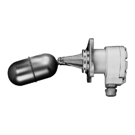
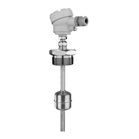
2.6. FLOAT SELECTION
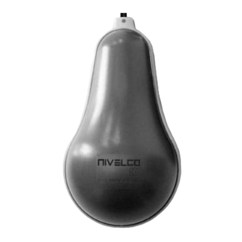
TYPE MRC-106-7M-900-00 MRC-105-7M-900-00 MRC-105-7M-600-00 MRC-105-7M-700-00 MRC-105-7M-800-00 MPP-105-3M-200-00 MPP-105-3M-900-00
Dimensions
Standard type ■■■■――
Plastic co. type ――――■■
Ex type ■■■■――
Medium-density
(Specific gravity)
min.
0.45 kg/dm30.55 kg/dm30.8 kg/dm30.55 kg/dm30.4 kg/dm30.7 kg/dm30.4 kg/dm3
Material Titanium 1.4404 1.4435 1.4401 PVDF PP
Med. pressure 2 MPa (20 bar)
[290 psi]
2.5 MPa (25 bar)
[363 psi]
0.6 MPa (6 bar)
[87 psi]
0.3 MPa (3 bar)
[43.5 psi]
3. INSTALLATION
For mounting the unit 1", 1½", 2" BSP or NPT threads or 1", 1½", 2½", 3", 4"
TriClamp can be used. Minimal gap diameter for the float is 55 mm
(2.16").
Use the M20×1.5 cable gland for electrical connection.
If a protection tube is used the minimum tube diameter should be 75 mm
(2.95") (for insertion length < 1.5 m and 95 mm (3.74") for insertion
length > 1.5m). When using a 96 mm (3.8") float the tube diameter should
be min. 130 mm (5.1").
WARNING!
Do not loosen the gland nut that ensures a ±25 mm (±0.98") adjustment of the
sensors in a pressurized container!
The unit should be mounted in vertical position via its process connection and
handled with care to avoid any damage or bend of the protection tube during
transportation or installation!
4. SET UP, ADJUSTMENT
After screwing in and before tightening the sliding sleeve the direction of the
cable gland and the position of the reed-relay set can be adjusted. an open-end
wrench should be used when loosening or screwing tight the sliding sleeve!
The position of the reed-relay set can be vertically adjusted by a max. of
±25 mm (±0.98").
5. WIRING
Depending on the grounding system either the inner or the outer grounding
terminal should be connected to the EP network.
Standard version
Remove the cover. Feed the electrical cables through the cable gland and
connect them in accordance with the sketch on the cover where the (NO/NC)
states of the relays are marked. The terminal of the lowest switch point has to
be number 1.
“C” is common terminal.
The cross section of the connecting cable has to be between 0.5 and 2.5 mm2
(AWG20…AWG14). After connecting, secure the cable with the cable gland,
check and screw the cover back on with at least 25 Nm of torque.
Ex version
Remove the safety clamp and screw the cover off. Feed the electrical cables
through the cable gland and connect them in accordance with the sketch on the
cover where the (NO/NC) states of the relays are marked.
After connecting, secure the cable with the cable gland, check and screw the
cover back on with at least 25 Nm of torque. Fasten the safety clamp by setting
it into one of the notches of the cover.
6. SPECIAL CONDITIONS OF SAFE USE
Make sure the installation is complete with no visible defects before turning
on the device.
The device may only be used within the limitations specified in the technical
specifications.
The installation of the device must be carried out in a way that the IP20 ingress
protection is maintained throughout the installation!
The thermal resistance of the connection cable insulation must correspond to
the permissible ambient temperature at the place of application.
The metal housing of the device must be connected to the EP (equipotential)
network!
WARNING!
Use exclusively Ex d IIC cable entry for devices with “Ex d” flameproof
protection!
The plastic protective cap should be removed before installing NIVOPOINT
MR☐☐☐☐8Ex, and the device must be equipped with a properly
assembled and sealed and cable gland with “Ex d” protection type.
The housing and measuring tube must be protected against mechanical
impact! The location and method of installation must be such that they are
protected against external mechanical influences during operation!
The aluminum content of the metal die-cast housing exceeds the threshold;
which require protection of the equipment against any possible sources of
spark or ignition resulted by impact or friction!
Devices with order code MR☐☐☐☐7Ex may only be installed with wiring
and cable ducts that complies with MSZ EN 60079-14: 2014 standard
10.6.2. b!
7. MAINTENANCE, REPAIR
The unit does not require regular maintenance. In some instances, however,
the probe may need occasional cleaning to remove surface deposits. This
must be carried out gently, without harming the probe.
All repairs will be carried out at the manufacturer’s premises.
Before returning the device for repairs, it must be cleaned carefully, the parts
in contact with the medium that might contain harmful substances must be
decontaminated. Our official form (Returned Equipment Handling Form) must
be enclosed. Download it from our website www.nivelco.com. The device must
be sent with a declaration of decontamination. Please provide a statement in
the declaration that the decontamination process is completed, the device is
clean and free from harmful materials, and there are no hazardous substances
on it.
8. STORAGE CONDITIONS
Ambient temperature: –20… +60 °C (–4…+140 °F)
mra105en2112h
April 2021.
NIVELCO reserves the right to change technical data without notice!
