manuals.online logo
Brands
  1. Home
  2. •
  3. Brands
  4. •
  5. NIVELCO
  6. •
  7. Switch
  8. •
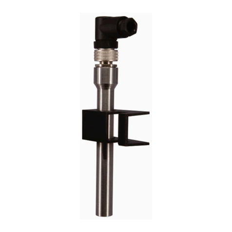
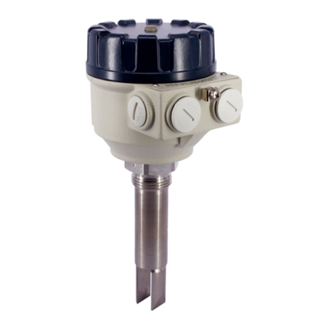
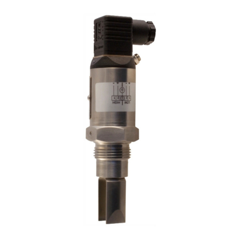
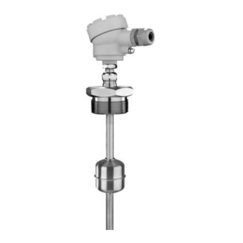
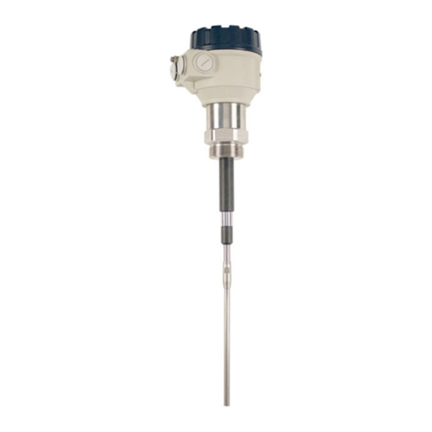
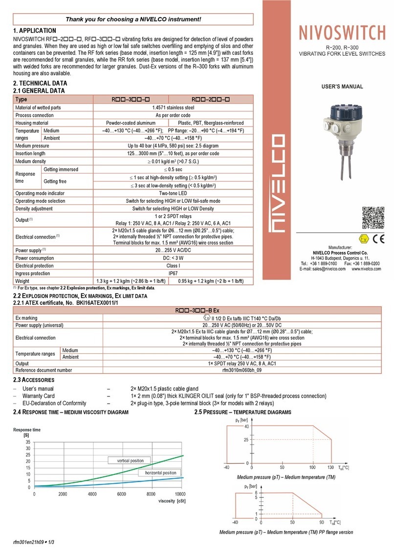
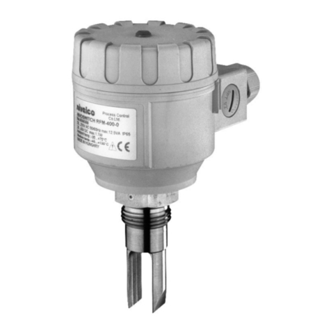
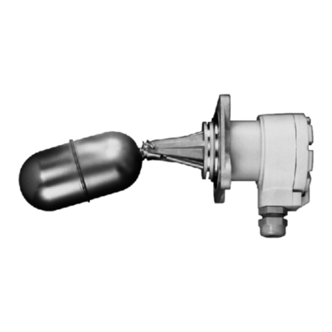
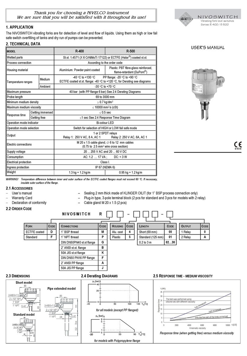
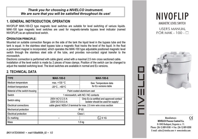
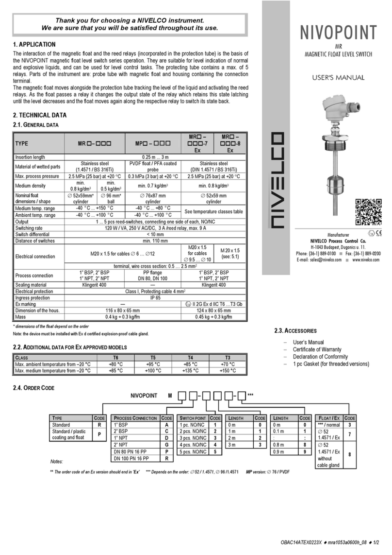
  9. NIVELCO NIVOSWITCH R-400 Series User manual

NIVELCO NIVOSWITCH R-400 Series User manual

rcm400en2112h 1/4
Thank you for choosing a NIVELCO instrument!
1. APPLICATION
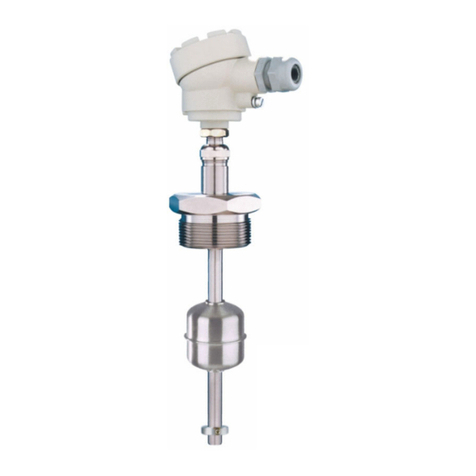
The NIVOSWITCH R–400 vibrating fork level switches are used for level or flow switching tasks of normal
and explosive liquids. Overfill and dry run protection, as well as pump control, are also possible with the
NIVOSWITCH vibrating fork level switches in low/high fail-safe operating mode.
2. TECHNICAL DATA
2.1 GENERAL DATA 2.2 2-WIRE DC, NORMAL AND EX APPROVED VERSION
R–4–6
R–4–Ex
Típus Type R–4–6
R–4–8Ex
R–4–K
R–4–LEx
R–4–7
R–4–9Ex
Medium pressure
40 bar (580 psi),
PP flange: 6 bar (87 psi)
see “Temperature diagrams”
Electrical connection Connector
3 m (10 ft) (1) cable
(2 x 0.5 mm2
[AWG20])
Insertion length 69…3000 mm (0.225…10 ft) Ingress Protection IP65 IP67 IP68
Material of wetted
parts
DIN 1.4571,
ECTFE / PFA coating Output
DC current change:
When free: 9 ±1 mA;
When immersed: 14 ±1 m
A
Medium
temperature
−40…+130 °C (−40…+266 °F)
see section 5.1 and 2.6
diagrams
Consumption < 0.5 W
Power supply (U)
15…29 V DC
Provided by the PKK–312–8Ex
remote switching unit for the Ex-version
Ambient
temperature
−40…+70 °C (−40…+158 °F)
see table in 5.1 and diagrams
R–4–L Ex;
R–4–M and –4–
K
−25…+70 °C (−13…+158 °F)
Setting operation
mode
By switch on the remote switching unit
(Low fail-safe – “L”, High fail-safe – “H”)
Medium-density 0.7 kg/dm3Electrical protection Class III.
Medium viscosity 10000 mm2/s (cSt)
Respons
e time
When
immersed 0.5 sec
Ex marking
(RC–4–Ex,
RG
–
4
–
Ex)
II 1G Ex ia IIC T6…T4 Ga
When free When free: 1 s
see response time diagram Ex marking
(RB–4–Ex) II 1G Ex ia IIB T6…T4 Ga
Output mode
indication Bi-color (LED) Intrinsic safety data
Ui= 29 V; Ii= 100 mA; Pi= 1,4 W;
Ci= 7 nF; Li= 0 mH
Ui= 29 V; Ii= 100 mA;
Pi= 1,4 W;
Ci= 15 nF; Li= 0 mH
Operation test Output can be toggled
by test magnet
For temperature classes, see section 5.1
Reference document
numbe
r
rcm4004m060bh_11
(1) Available max. cable length 30 m (100 ft)
2.3 2-WIRE AC AND 3-WIRE DC VERSIONS
TYPE 2-WIRE AC 3-WIRE DC
R
–
4–1 R
–
4–2 R–4–3 R–4–M R–4–4
Electrical connection (wire cross section) Connector
3 m (10 feet) integral cable,
4 x 0.75 mm2(AWG18)
(max cable length 30 m [100 feet])
Connector
3 m (10 feet) integral cable,
5 x 0.5 mm2(AWG20)
(max. cable length 30 m [100 feet])
Mechanical protection IP65 IP68 IP65 IP67 IP68
High/low mode setting
(Low fail-safe
–
“L”, High fail-safe
–
“H”)
Determined by the wiring inside
the connecto
r
Determined by the wiring Switch selectable Connection within
connecto
r
Wire selectable
Output 2-wire AC, for serial connection Field selectable,
NPN / PNP transistor switch
Field selectable, galvanically
isolated PNP/NPN transistor switch
Output protection — Reverse polarity, over
c
urrent and short-circuit protection
Supply voltage 20…255 V AC, 50/60 Hz 12…55 V DC
Consumption Depending on the load < 0.6 W
Voltage drop when switched on < 10.5 V < 4.5 V
Electrical protection Class I Class III
Load current
max. continuous 350 mA
A
C 13 Imax = 350 mA DC / Umax = 55 V DC
min. continuous 10 mA / 255 V, 25 mA / 24 V
–
max. impulse 1.5 A / 40 ms
–
Residual current (in switched off state) < 6 mA < 100

A
2.4 ACCESSORIES
- User’s manual - EU- declaration of conformity
–
A
ccessories (sold separately): -
A
djustable sliding sleeve (RPH
–
112
–
0)
- Warranty Card - 1× Sealing ring (2 mm [0.079"] thick Klinger Oilit) - Test magnetic-screwdriver (RPS
–
101)
2.5 ORDER CODES NIVOSWITCH R –
4 – *
TYPE CODE PROCESS CONNECTION CODE PROBE LENGTH CODE OUTPUT CODE
Tube + plastic
(ECTFE / PFA) coated fork B 1" BSP M Short (69 mm [2.7"]) 00 2-wire
A
C + connecto
r
1
1½" BSP H Standard (125 mm [4.9"]) 01 2-wire
A
C + cable 2
Tube + for
k
: 1.4571 C 1" NPT P 0.2…3 m (0.66…10 feet) 02…30 3-wire DC + connecto
r
3
Tube + highly polished fork G 1½" NPT N 3-wire DC + cable 4
Tube + for
k
: 1.457, without reed senso
r
(1) E DN50 PN16 PP DIN F 2-wire DC + connecto
r
6
(1)Ex version not available DN50 PN40 1.4571 DIN G 2-wire DC + cable 7
A
NSI 2" RF150 PP
A
2-wire DC + connector + E
x
8
A
NSI 2" RF600 1.4571 B 2-wire DC + cable + E
x
9
JIS 10K 50A PP J 2-wire DC + M12 connecto
r
K
JIS 40K 50A 1.4571 K 2-wire DC + M12 connector + E
x
L
TriClamp 1½" T 3-wire DC + M12 connecto
r
M
TriClamp 2" R
DN40 Pipe coupling D * Ex version with E
x
mark
DN50 Pipe coupling E Note: Flanged versions have 1" process connection
2/4 rcm400en2112h
2.6 TEMPERATURE DIAGRAMS
Pressure [pT] as a function of temperature [TM] for all versions
(except PP
-
flange
d
version)
55
45
35
I
L
100 mA
I 1mA
L
I350mA
L
95
105
130
115
70
T[°C]
M
T[°C]
A
-40
-40
The thermal
limits of DC versions, [IL] load current
0
050
p [bar]
T
6
5
1
-20 90 T[°C]
M
Pressure [pT
]
as a function of temperature [TM
]
for PP flanged version
55
130
115
70
T[°C]
M
T[°C]
A
-40
-40
Temperature limits of AC versions, [TA] ambient temperature
[TM
]
medium temperature
2.7 RESPONSE TIME DIAGRAM
(when the level of the medium drops below the fork)
2.8 DIMENSIONS
R–400–R–4–
Version with sliding sleeve
RCM–4–+ RPH–112–0
Version with flange
RCF–4–
TriClamp (ISO 2852)
RCT–400–, RCR–400–
Pipe coupling (DIN11851)
RD–4–, RE–4–
2.9 MATERIALS
3. INSTALLATION
Protect the device from any mechanical damage.
To adjust the position of prongs use the marking on the hexagonal neck.
If the prongs have to be positioned
directionally (side mounting), use Teflon
(PTFE) tape to seal the thread and
position the prongs.
In this case, vertical positioning of the fork
is suggested.
rcm400en2112h

3/4
Low-viscosity liquids
If the measured medium is a
low-viscosity liquid, the position
of the prongs is irrelevant.
High-viscosity liquids
If the measured medium is
highly viscous, mounting the
fork horizontally is
recommended.
Installation options
Threaded version Flanged version, critical distances x > 5 mm (0.2")
For pipe mounting,
the prongs
must be parallel to the direction of flow
Switching point and differential for water at 25 °C (77 °F)
The switching point, and the switching differential, depends on the liquid
density and mounting position.
4. WIRING
4.1 3-WIRE AC VERSIONS R–4–1 (connector)
R–4–2 (cable)
Do not power up the device without a load connected in series
with the unit and without grounding it!
4.1.1 Version with connector R–4–1
“L” Low-level limit switch “H” High-level limit switch
The terminal block cover can be rotated in 90° steps to ensure appropriate cable
positioning.
4.1.2 Version with cable R–4–2
This version is equipped with a 4-wire cable. Only one of the black and brown
wires is used, depending on the operating mode (high or low).
Connect the unused wire to an unused terminal in the terminal block.
“L” Low-level limit switch “H” High-level limit switch
4.2 3-WIRE DC VERSIONS
If there is overload caused by a short circuit, the transistor will switch on and off,
and the LED will start to blink.
4.2.1 Version with connector R–4–M, R–4–3
4.2.1.1 Wiring of the 3-wire DC version with connector in a relay application
PNP wiring NPN wiring
The terminal block cover can be rotated in 90° steps to ensure appropriate cable
positioning.
PNP output
“L” Low-level limit switch “H” High-level limit switch
NPN output
“L” Low-level limit switch “H” High-level limit switch
4.2.1.2 Wiring of 3-wire DC version with connector in case of PLC application
PNP wiring
4.2.2 Version with cable R–4–4
4.2.2.1 Wiring in case of relay applications
PNP output
“L” Low-level limit switch “H” High-level limit switch
4/4 rcm400en2112h
NPN wiring
“L” Low-level limit switch “H” High-level limit switch
4.2.2.2 Wiring in case of PLC applications
PNP wiring
“L” Low-level limit switch “H” High-level limit switch
4.3 2-WIRE DC VERSIONS,NORMAL OR EX
4.3.1 Version with connector
R–4–6
R–4–8Ex
R–4–K
R–4–LEx
4.3.2 Version with cable R – 4 – 7
R – 4 – 9Ex
5. COMMISSIONING AND, ADJUSTMENT
Check the wire connections and the position of the operating mode switch
(if there is one). After connecting and powering up, the vibrating fork is
operational.
The operating diagram of the NIVOSWITCH:
Power
supply Fork Mode Display
(LED) Output
ON
Immersed
High Red OFF
Low Green
ON
Free
High Green
Low Red
OFF
NONE
Free
or
immersed
H
or
L
Off
Operation diagram of the 2-wire DC version
Fork Display (LED) Output
Immersed
Red 14 1 mA
Free
Green 9 1 mA
OPERATION TEST
The correct operation of the switching circuit of an installed
device can be tested with the optional test magnet
(RPS–101).
Moving the test magnet in front of the mark on the cover of
the housing, the device will perform a switching
(LED changes color).
5.1 APPLYING EX APPROVED MODELS
When using an Ex-approved model, mind the table of thermal limits below.
Temperature
classification T6 T5 T4
Tambient 70 °C (158 °F) 60 °C (140 °F) 60 °C (140 °F) 60 °C (140 °F)
Tmedium 70 °C (158 °F) 75 °C (167 °F) 95 °C (203 °F) 130 °C (266 °F)
Table of possible temperatures
Recommended Installation
5.2 CONDITIONS OF SAFE OPERATION
xII 1G Ex ia IIC T6…T4 Ga and xII 1G Ex ia IIB T6...T4 Ga approved vibrating
forks must be powered by intrinsically safe [Ex ia IIC or IIB] certified and approved
devices.
These units must be cleaned only with a damp cloth.
A junction box must be used to wire the cable connection version
R–4–9Ex devices. The junction box must meet the applicable safety
requirements.
The instrument has built-in overvoltage protection, so:
Outer grounding of the housing must be connected to the steel silo wall with
a minimal 4 mm2(AWG12), shielded copper cable ─outside the Zone 0 ─
within 1 m (3.3 ft) of the boundary of the Zone 0.
According to 6.3.12 of EN 60079-11, the standard dielectric strength test
must not be performed on the instrument.
To avoid the accumulation of electrostatic charge when using the coated version
of the RB–4–the following safety rule must be observed:
The measured medium must be electrostatically conductive, the electrical
resistivity of the medium must be 104.
The speed of the filling and emptying process must be chosen properly
according to the measured medium.
6. MAINTENANCE AND REPAIR
The sensor probe may need occasional
cleaning to remove surface deposits. This
must be carried out gently, without harming
the vibrating section of the vibrating fork.
Before returning the device for repairs, it must be cleaned thoroughly. The parts in
contact with the medium may contain harmful substances; therefore, they must be
decontaminated. Our official form (Returned Equipment Handling Form) must be
filled and enclosed in the parcel. Download it from our website www.nivelco.com.
The device must be sent back with a declaration of decontamination. A statement
must be provided in the declaration that the decontamination process was
successfully completed and that the device is clean from any hazardous
substances.
7. STORAGE CONDITIONS
Ambient temperature: −40…+70 °C (−40…+158 °F)
Relative humidity: max. 98%
rcm400en2112h
September 2021
NIVELCO reserves the right to change anything in this manual without notice!

Other NIVELCO Switch manuals

NIVELCO NIVOSWITCH R-2 Series User manual

NIVELCO

NIVELCO NIVOSWITCH R-2 Series User manual

NIVELCO MR Series User manual

NIVELCO

NIVELCO MR Series User manual

NIVELCO NIVOSWITCH R-400 Series User manual

NIVELCO

NIVELCO NIVOSWITCH R-400 Series User manual

NIVELCO NIVOSWITCH R-400 Series User manual

NIVELCO

NIVELCO NIVOSWITCH R-400 Series User manual

NIVELCO NIVOCONT R Series User manual

NIVELCO

NIVELCO NIVOCONT R Series User manual

NIVELCO NIVOPOINT User manual

NIVELCO

NIVELCO NIVOPOINT User manual

NIVELCO NIVOCONT K User manual

NIVELCO

NIVELCO NIVOCONT K User manual

NIVELCO NIVOFLIP MAK-200 User manual

NIVELCO

NIVELCO NIVOFLIP MAK-200 User manual

NIVELCO NIPRESS DK-300 Assembly instructions

NIVELCO

NIVELCO NIPRESS DK-300 Assembly instructions

NIVELCO Nivocap CK User manual

NIVELCO

NIVELCO Nivocap CK User manual

NIVELCO NIPRESS DK-500 Assembly instructions

NIVELCO

NIVELCO NIPRESS DK-500 Assembly instructions

NIVELCO NIVOFLOAT NW-100 Series User manual

NIVELCO

NIVELCO NIVOFLOAT NW-100 Series User manual

NIVELCO R-400 User manual

NIVELCO

NIVELCO R-400 User manual

NIVELCO NIVOSWITCH R-400 User manual

NIVELCO

NIVELCO NIVOSWITCH R-400 User manual

NIVELCO NIVOMAG MK-21 Series User manual

NIVELCO

NIVELCO NIVOMAG MK-21 Series User manual

NIVELCO NIVOFLIP MAK-100 Series User manual

NIVELCO

NIVELCO NIVOFLIP MAK-100 Series User manual

NIVELCO NIVOPOINT MR Series User manual

NIVELCO

NIVELCO NIVOPOINT MR Series User manual

Popular Switch manuals by other brands

i3 International SW-570 user manual

i3 International

i3 International SW-570 user manual

jablotron UC-230 quick start guide

jablotron

jablotron UC-230 quick start guide

Sony DMX-SW1 - Bravia Input Link operating instructions

Sony

Sony DMX-SW1 - Bravia Input Link operating instructions

TRUE MODS PIM-00000173-V002 manual

TRUE MODS

TRUE MODS PIM-00000173-V002 manual

Telecom Behnke 20-9598 instructions

Telecom Behnke

Telecom Behnke 20-9598 instructions

Avaya P332GT-ML Installation and configuration guide

Avaya

Avaya P332GT-ML Installation and configuration guide

Avenview HDM2-SPLITPRO-T4K-V2 manual

Avenview

Avenview HDM2-SPLITPRO-T4K-V2 manual

Cisco Nexus 5548P datasheet

Cisco

Cisco Nexus 5548P datasheet

SCHUNK MMS 22-PI1 Commissioning instructions

SCHUNK

SCHUNK MMS 22-PI1 Commissioning instructions

CP Plus CP-DNW-GPU8G2-96-V4 quick start guide

CP Plus

CP Plus CP-DNW-GPU8G2-96-V4 quick start guide

Phonak roger Quick setup guide

Phonak

Phonak roger Quick setup guide

GEYA GRT8-LM instruction manual

GEYA

GEYA GRT8-LM instruction manual

Manhattan 151252 user manual

Manhattan

Manhattan 151252 user manual

GrandTec POE-5000 Quick installation guide

GrandTec

GrandTec POE-5000 Quick installation guide

HP 1410 series specification

HP

HP 1410 series specification

Foundry Networks NetIron M2404C installation guide

Foundry Networks

Foundry Networks NetIron M2404C installation guide

NETGEAR EN308TC - 8 Port 10 Base-T Hub installation guide

NETGEAR

NETGEAR EN308TC - 8 Port 10 Base-T Hub installation guide

Force 10 Traverse Series Installation and commissioning guide

Force 10

Force 10 Traverse Series Installation and commissioning guide

manuals.online logo
manuals.online logoBrands
  • About & Mission
  • Contact us
  • Privacy Policy
  • Terms and Conditions

Copyright 2025 Manuals.Online. All Rights Reserved.